VapCap DIY Induction Heating : Bits 'n' pieces

BirdFisher

Member
Everything seems to work pretty good now, with the 6A PSU, only when I put the vapcap too low / deep in the coil, the IH won't start. Can I try with more current, would this kind of PSU work ?

Oh, and one more thing, what is a cheaponic? :)
 
BirdFisher,
  • Like
Reactions: Madri-Gal

Abysmal Vapor

Supersniffer 2000 - robot fart detection device
Everything seems to work pretty good now, with the 6A PSU, only when I put the vapcap too low / deep in the coil, the IH won't start. Can I try with more current, would this kind of PSU work ?

Oh, and one more thing, what is a cheaponic? :)
http://fuckcombustion.com/threads/the-cheaponic-cheaper-than-papes.28612/
Yes my gf uses 10A for her IH and it is rock solid since day 1.
For cheaponic it is best to have 16/100 for the otside and 12/120-150mm for the bowl. It also works 16/75mm with a 12/100-150 for the bowl. Those are pretty commont sizes so you wont need any glass cutting :).
 
Last edited:
Abysmal Vapor,
  • Like
Reactions: Madri-Gal

BirdFisher

Member
Hey do you know if there exists a (even basic) schematic diagram of those ZVS IHs somewhere? Reason I ask is because I'd like to replace the MOSFETs on the ones that I fried.
 
BirdFisher,
  • Like
Reactions: Madri-Gal

PKOK

Well-Known Member
@stardustsailor I' getting about 33% of this, a little more each time I read it. I was mechanical :uhh:
The only shop I've ever used
for PCB's is OSHPARK they do beautiful work w/fast turnaround BUT they work with KiCAD, EagleCAD, or zipped Gerber files. Would it be possible for you to output in one of these formats?
https://oshpark.com/

I just noticed BirdFishers post above me and me has a point why not lay out a PCB for the ZVS
it's self. It sure would get rid of a lot of problems.....well I assume your the EE :hmm:

 
Last edited:

PKOK

Well-Known Member
Oh forgot to mention they have a "shared" area that once you upload your design they sell it to anyone all
nice and neat for very little. They do give you credit for the design and any notes you want to pass on , I believe.
 

PKOK

Well-Known Member
Dang, stupid is as stupid does, I see it now post #69. I believe that DipTrace will export in most any format.
Bear with me guys I'm catching up:doh:
 

TommyDee

Vaporitor
I've decided that a 10A DC rated switch is more than sufficient to run this thing and simplify the wiring. I also want to be sure that any power switch is momentary.

Current state of my daily driver IH;

49589997181_114e844374_b.jpg


This has the 20A BMS on the end of the 3x 18650 cell holder so I can charge it with a USB w/ 12.6V boost driver. The switch is on the mains and is Momentary 'ON' on push, and 'ON' on pull. 10A protected cells would work in the circuit but not in these battery holders.

I'm finding this package to be a bit oversized. Not a lot you can do with it but there it is. I don't really like the bulk of this even if it was boxed and I don't like the umbilical cord with the cells in my pocket. So far I am hating this configuration a little less than the corded version.
 
Last edited:

PKOK

Well-Known Member
TommyDee Nice work. Form fit and function come before beauty in my book. I've seen that switch in
others builds, would you mind sharing a link for it? Oh those Teflon tubes as well- I can't find them to save my ass. Aftermarket wire on the coil?
It looks like it'll get ya down the road for awhile.i keep smoking mine in testing.....I think it may have something to do with the smoke :science:
 

TommyDee

Vaporitor
Thanks. Definitely a workhorse. The part number in the image is still valid - E6930A. Today's manufacturer is Zf. Newark carries them - cheap.

Coil is stock with a long run soldered to the PCB. Teflon tube is 2mm ID 3mm OD - eBay/Amazon PTFE is easier in search.

The vials are shipping material from a carbon fiber company. They come from Cole-Palmer in 100-lots. Lots of glass out there but this offers a 'floor'

edit: 16 amp version - https://www.digikey.com/product-detail/en/e-switch/PP1-EB7-1A2/EG4872-ND/2391244

I resoldered all the solder joints on mine. Most joints only had a fillet on one side of the board. I don't trust vias that far.
 
Last edited:

TommyDee

Vaporitor
Went for a new compacting of the China-offering. Found something interesting in a mistake. I completely spaced the center leg of the two coils. I had it in mind this was just a series pair of coils. It is in fact a center-taped coil with separate cores. What was interesting is that is drew zero current.

That means everything balances on this center tap. At the same time I did some measurements across the 470 ohm control-power resistors. They loose between 8-10.5V!

The compact size lent itself to yesterdays version. Let's see how hard it will be to power that center leg in this con figuration.

49600146413_b194c8d3f1_c.jpg


Got some ideas about a DIY switch too.

I corrected my brain fart from yesterday and the circuit lives. Took it a few tries to get it to fire and it even went through a reset routine of some kind [balancing routing]. The power died to the LED and came back after some 2-3 seconds. Once the caps got their fill, its been working great.

Now that I've improved the conductive path, this thing's become a beast! And not in a good way. It gets freakin' hot! Two things have changed; 1) I compressed the coil, and 2) have very little voltage loss from the power supply to the IH. Still requires 10 seconds to click-2.

What I was hoping to achieve with the tighter coil is to focus the energy to the bowl. I suspect it is doing that and lessening the heating of the cooling fins. And I will reiterate again - MOMENTARY SWITCH! You don't want to leave this on for long. It will burn you! Sessions with cutting power except to heat the VC is still palmable.

I am now delivering 11.5V at full load of the available 12V. I am on the edge of a 2 amps current draw without load. With a stainless steel VC, I get almost 8 amps of current flow. I also noted that when I turned the voltage down, current went up, and the unit actually went through a reboot cycle. That is so odd since there is no processor.

49600527353_32d7361896_c.jpg

49601286242_f258e45338_c.jpg


As to the build. Again, the goal was compact design and a compact coil. I have no idea how badly this thing causes internal losses due to this configuration. These coils have magnetic fields that can affect other functions.

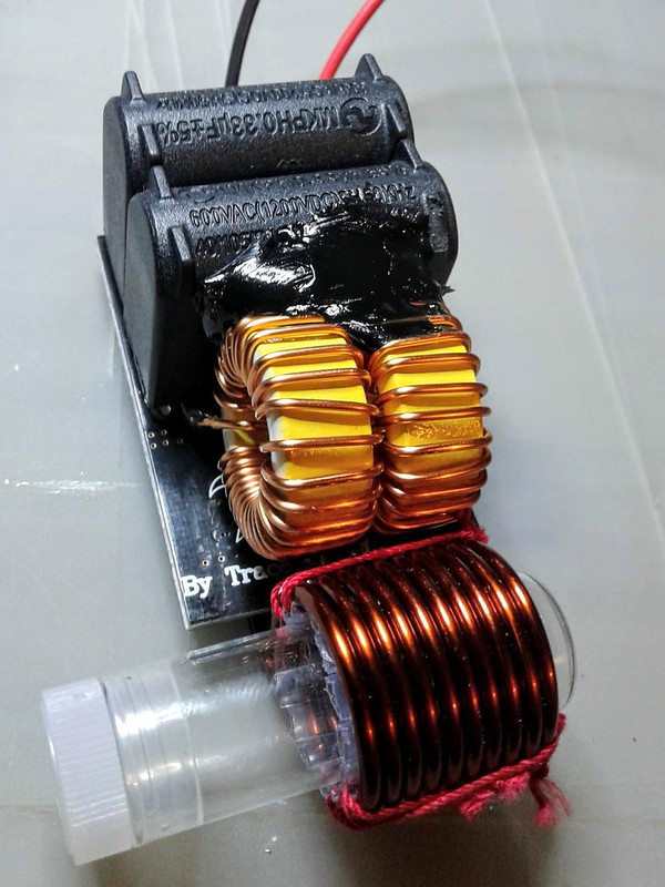
The final size ended up being 3"x 1.5"x1.38". The bare wire shown in the images is 14 awg. 16 awg should be sufficient at these short runs.
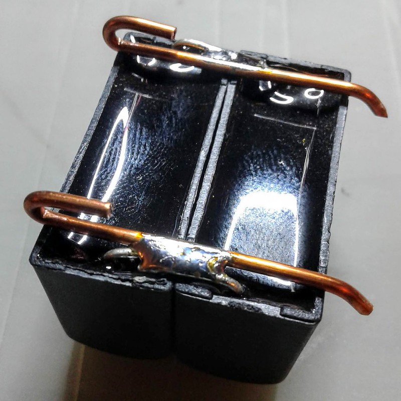
Pairing the caps;
49600527158_9b7cff2901_c.jpg


Merge coils;
49600527208_e216e0181a_c.jpg


The center-tap I forgot - This joins up with the +in pad. Sorry for the shitty image quality.
49600527243_be364065e7_c.jpg


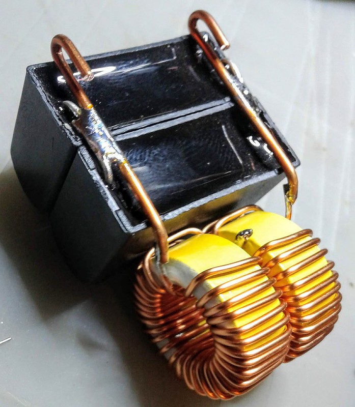
And the final merging to the board; There is room to reach in for the coil's center-tap lead-wire.
49601025846_5fe8157fdd_c.jpg


Shape and locate the coil to your liking and solder it to the board. Add power wires and done.
49601394577_94626552c2_c.jpg


Now to get some switches.

For a real-time IH, the power will need to be reduced significantly. This means less turns on the inductors. Less coil turns and less diameter, and fewer wraps around the ferrite core. I have one more circuit coming and I'll see what it takes to get this down to 1/2 the output.
 
Last edited:

TommyDee

Vaporitor
D'uh! Power levels :bang: These thing do work proportionally to the power provided.

I'm running a 12 volt 10 amp supply similarly to what my 18650 can deliver. Unlike my previous build, I am running 'the runt' on 14 gauge 'hard-wire' except for the 18 gauge power run which dropped 1/2 a volt @ 8 amps. That makes me think that resistance in the wire can be used as a current limiter. It is obviously lost to heat but it is a worthwhile perspective of managing power levels while keeping things simple.

Two things already noted; 1) yea, this is a good size for real-time v-cap heating, and 2) This 'current limit by resistance' drops the load to 6 amps at 10 volts to the device. This is 14500 territory. Back to the umbilical cord :hmm:

Anyone care to try a 'half-pint' version? One capacitor and one of the paired coils. Center-tap the remaining coil for the positive input by scraping the enamel and direct-soldering the wire to the coil. This will reduce the output by 2 and allow for a much shorter antenna coil (the working coil). The reduced power level would definitely be welcome on a sustained heating while drawing. For those who like terpe hits, doing a slow roast to ABV bliss should provide a very rewarding session.

With a hot IH, which 'the runt' is, all out performance overwhelms the heat cycle if you are the feedback loop. You will flame-out before you realize the temp's gone up. It is a good way, but the response time is too slow. With the current-modulated version, it is slower to heat up (strange, unsprung coil was more efficient!). However, real time heating while drawing was much more manageable. This doesn't say much for waterworx, but you get my drift. I can detect heat while drawing and cut power before combustion using the higher loss wiring setup. The aim on this device is 50-60 watts for a sustained heating. What it does come down to is that you have more heat that you could ever draw through the VC.

Anyone know if an IH can handle a PWM input without blowing up the FETs?

--------------------------------------
With a switch on a longer length of 22 gauge lead-wires slows the process down enough to have a chance at modulating the heat cycle. Your draw will just about keep up with it. I'm seeing 8 volts and 5.5 amps [44 watts] in this circuit. We're almost in 2x 18650 territory. This rocks! And don't forget, the clicker is still available, just less important since you are already enjoying the more delicate offerings rather than destroying them - or rather 'taking them and storing them out of hams way.' In this arrangement, it is not going to replace the IH, but it is an excellent starter-vape version. I promise you better efficiency of your herb!
 
Last edited:

TommyDee

Vaporitor
Anyone know what zener they use on the ZVS board?

Alrighty-then; found my 2S 18650 pack. Plugged it into the DD-IH; 8.3v idle; 7.8v @ 1A; 6.5v @ 4.5A. That's say 30 watts.

If you ever wanted control over your VapCap, this is it! ...if you don't drift off and forget to let go of the button!

Therefore yes, you can snap a cap with 2 li-ion cells on the ZVS IH. :rockon:

I need to see if 2S 14500 will hold up to 5 amps. I expect I can get this in the 40 watt range if I can minimize input voltage losses.
 
Last edited:

PKOK

Well-Known Member
Neat stuff Tommy Dee. You know these things in general last longer than I would have thought, without upgrading. That's some cool stuff, so you coiled with 22 gauge lead-wires?
I like the open board, access to the mosfets. Have you ever upgraded those on a stock ZVS?
My first is a few months old and I can see stress but no failures. This is addictive.
 

TommyDee

Vaporitor
I am getting a little too deep into it but this is fun. I order a couple more switches from Digikey this morning. I got the 16A ones this time.

Considering this unit is rated at 120W, I am not worrying about the power level. With a good solid 12V, the VC is a little smaller than the allowable load (material to be heated). I could barely get to 100W with the Stainless VapCap.

So far so good on the line-voltage switch. Early on I saw the unit 'balance' but after that is has behaved perfectly. Each activation turned the IH on without hesitation with or without the VC installed.

I am also very presantly surprised that there are no hazardous voltage levels going on. There is nothing that really bites me holding it my hands other than the bottom of the glass vile. It gets very hot from the cap. Otherwise I can do an entire session without the IH getting hot. First thing to get hot is the coil. The momentary switch is really making keeping this cool very easy.

I did reduce the voltage going into the IH using 22AWG in the 14500 setup. Basically I am just using a resistor to reduce the power level. For a 2x 18650, wire it like you want zero losses. That is for a very slow roast of the cap while drawing. It will click both clicks just to keep your somewhat grounded. I've already spaced holding the switch once. With the reduced power, the runaway freight train of a full fledged IH is moving a little slower so you can catch the falling knife.

And thanks @PKOK - not many people enjoy open frame widgets. I find it quite appealing when it is stout enough to handle :tup:
 

LesPlenty

Well-Known Member
Company Rep
Here is my homemade job(I only use my SJK IH for rosin collection duties).
Less than $10 if you have 18650x2,
Housed in a Narva Terminal bulk pack,
img_20181112_144117-jpg.5794

img_20180928_153531-jpg.5046

A few bits of glass and a CFx concentrate container for my own Rosin Vape...and it worked!
img_20190713_211046-jpg.10768

All the parts can be screwed together, no solder required. (switch has been replaced since the pic with a screwed in terminal job along with removing the tape on the coil):tup:
 

TommyDee

Vaporitor
I wonder what that adds up to in individual auctions.

IH w/ coil $8.00
BMS $1.50
Power switch $0.50
FET Switch $1.00
Charger $3.00
Battery Meter $1.25
Tactile switch $0.50
Power socket $0.75
Wire $1.00

$17.50 every day for the DIY'er. Now add cells ($15-30) and a battery holder ($2.00).

I would switch up a few things from that kit. Today I found a sweet momentary switch with a very light push similar to the white switch but much less throw.
It is rated to 15 amps for motors up to 1HP. It is still sizable but it is slim with mounting holes. Looks like this place has a good collection of them.
Basically, I haven't found a reason to simply put a switch on the main input. As long as the switch is rated for the power requirement, the IH has been perfectly happy dumping the full load with the VC installed on power-up.
BMS and charging is still a conundrum. I burned out one of those chargers last night. It needs some kind of current limit. They don't work well at full load for long. Of course I made the cell pack to easily remove the cells. I want to be able to keep the cells topped off while the unit is not in use, but every so often I will need to re-balance them. this also means I can charge the cells with 12V instead of 12.6V. It doesn't have to be topped off each time. 4V per cell is more than enough charge.

I still want to make the real-time VC heater a single handheld device. Maybe 2x 14500... very marginal but certainly doable on a charging dock.

The next IH I rebuild will be 1/2 the circuit. Only 1 black cap and only one ferrite coil tapped in the middle for the power lead. Got 15 gauge heating coil wire on order. Yesterday I ran something at about this level of power on my first session. The cap finally clicked once when I had my fill on the draw. That one hit was enough to raise the mind's fog to a recognizable level. And it was so good tasting!

Seriously people, I need your help. Who has determined the right voltage for the zener diode in the circuit? I'm giving serious consideration to laying out a board to manage just the switching components. This is the last component that happens to be a mystery.
 

PKOK

Well-Known Member
I'm giving serious consideration to laying out a board to manage just the switching components. This is the last component that happens to be a mystery.

Has anyone done a small run of the boards Stardustsailer has listed on Pg 3, post #69 ?
I got components on order for the Mosfet Switch / Debouncing board. BUT I installed DipTrace and pulled up the file it seems complete but I'm not a user of the software, so I haven't ordered the board. ALSO on the same post at the bottom and the right half of the schematic...isn't that the ZVS Driver ? Has anyone laid out this board? I've found not one opensource file for an IH...well Danavap size.
 

PKOK

Well-Known Member
I'm giving serious consideration to laying out a board to manage just the switching components. This is the last component that happens to be a mystery.

Has anyone done a small run of the boards Stardustsailer has listed on Pg 3, post #69 ?
I got components on order for the Mosfet Switch / Debouncing board. BUT I installed DipTrace and pulled up the file it seems complete but I'm not a user of the software. ALSO on the same post at the bottom and the right half of the schematic...isn't that the ZVS Driver ? Has anyone laid out this board? I've found not one opensource file...well Danavap size, I wonder why
 
PKOK,
Top Bottom