Maybe I should elaborate on my case for a balance charger first - I need a dockable 2S solution and this is perfect for just a charger on a stationary charging dock.
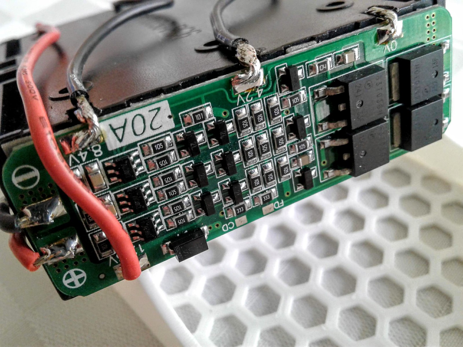
Your project, indeed, use the 20A board. Route through the FETs as intended. That is how I set up the pack in the previous pages. This will take care of 95% of your safety concerns.
The charger comes in on the output of the BMS. That is why you shouldn't use a device while a charger is plugged in -unless- it is rated for the load. Voltage to the cells is divided 3 ways so the output needs to be 12.6V or less. If the source is not stable then yes, you need a regulator in front of the battery pack/BMS for the charge system. Again, things are muddy here but it is a stern warning. Technically there is a voltage limiter in the regulators that control this process. However, the circuit is not very robust so without confirmation, I wouldn't charge over a 1/2 amp rate.
LM2596 is a great regulator used in CV|CC mode. I even have a few. I voided two issues in my setup - undue heat and headroom. Undue heat because the LM2596 circuits are handling 6 watts. Without some level of cooling effort, I don't like its odds... or the odds of whatever it sits on. I am also not impressed by their stability unless you do some active limiting to the range of the trimpot for voltage. If you can get a circuit under control and into a box with some cooling and a heatsink, you got a decent charger.
I have a 99c wall wart that puts out 12.45v and can't put out more than an amp. The 5W resistor is overkill to manage heat. The charge rate is 0.3 amps. I'm $2 into a charger that fails open circuit and protected from short circuit or over-voltage through the BMS. I'm covered! Walk inside the house and plug it in like I do my phone - charge overnight. The BMS is my 3rd level of protection. I am line isolated by a UL approved technique on the wallwart end. But this is also me cheaping out. But not without serious consideration of the ramifications. I am a lot more exposed with exposed battery terminals. And on headroom - I have a 12V/10A supply that I can crank up to 12.6 but I need much more to get stable regulation, 13.8v preferred.
There are choices. They all mean something. I want to narrow down to your desired requirements.
As to mains... terminology has really drifted over time on a lot of things so you can locally follow my meaning. DC- is what is switched in the BMS. DC+ just passes through. Output is the input for the charge circuit. Again, it is not recommended operating the the battery pack while charging.
...physical switch or a FET switch?
For posterity - That's negative on this end for all cells in the holder.
See how negative goes into the BMS and comes out the other end next to the red wire? That is the full current from the load going through the FETs. We use 5-8 amps so these may get warm.


 tell me about it. Where I'm getting lost is how I bring mains power in for charging unless I use a Power Regulator with the Balancing Board.


 But the way I collect parts we