TommyDee
Vaporitor
Thanks for pointing that out. Definitely worth reposting the schematic.
The other note in that post was about maximum gate voltage.
Now I under stand the 470 ohm resistors.
That should also mean those zerers are in the 2.1V range.
Also note that the LED circuit is omitted.

I do want to lay out a board but not sure I'll order any. I'm going to wait and see how this 'half power' version will function. If that works out as a mini-portable, then I won't have a choice but to lay one out.
And if anyone ever wanted to lay out PCB's but simply lack the tools - Go find Design Spark. They have some very powerful freeware. I know how PCB's are designed but that is not my discipline. I was able to lay out a fairly demanding PCB using their PCB software and had them made. Came out perfect! 3 times no less!
The other note in that post was about maximum gate voltage.
Now I under stand the 470 ohm resistors.
That should also mean those zerers are in the 2.1V range.
Also note that the LED circuit is omitted.

I do want to lay out a board but not sure I'll order any. I'm going to wait and see how this 'half power' version will function. If that works out as a mini-portable, then I won't have a choice but to lay one out.
And if anyone ever wanted to lay out PCB's but simply lack the tools - Go find Design Spark. They have some very powerful freeware. I know how PCB's are designed but that is not my discipline. I was able to lay out a fairly demanding PCB using their PCB software and had them made. Came out perfect! 3 times no less!

 , take a look at the Mosfet/Debouncer jobbie, see what you think.
 .
.

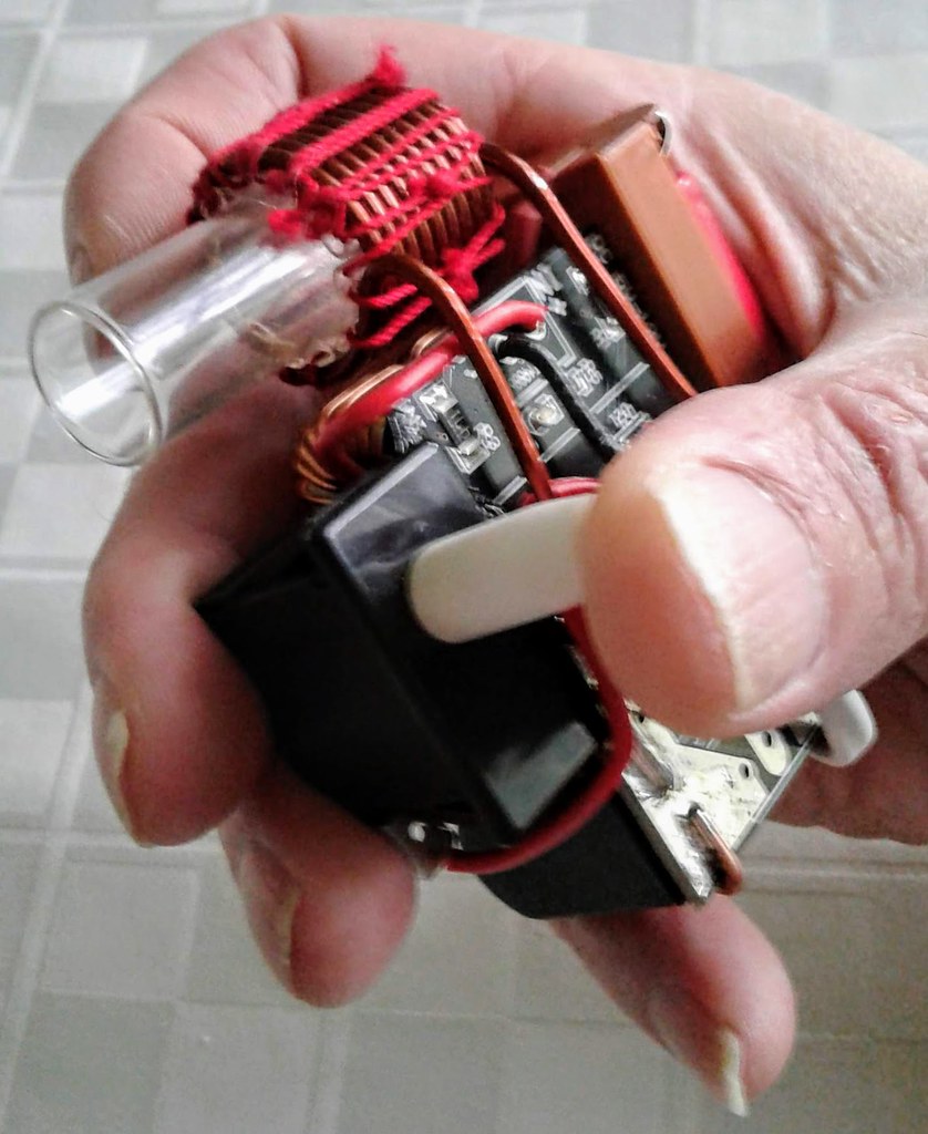
 I have no issues with breaking up the mains because I also have no use for a switch activation at the end of the coil. I am focusing on a "ReHeater"... or whatever a cleaver name will end up being. Having a switch at the end of the coil is not helpful if all you want to do is add heat to your current draw. This is where my focus is. This last switch I found would lend itself to activation of the unit and still break the mains. It is a 1/2" 1/2" 'log' with a small 1/4" button that has a very light actuation. For desktop, drop a marble in the glass coil-tube and you got a mains switch rather than a FET switch.


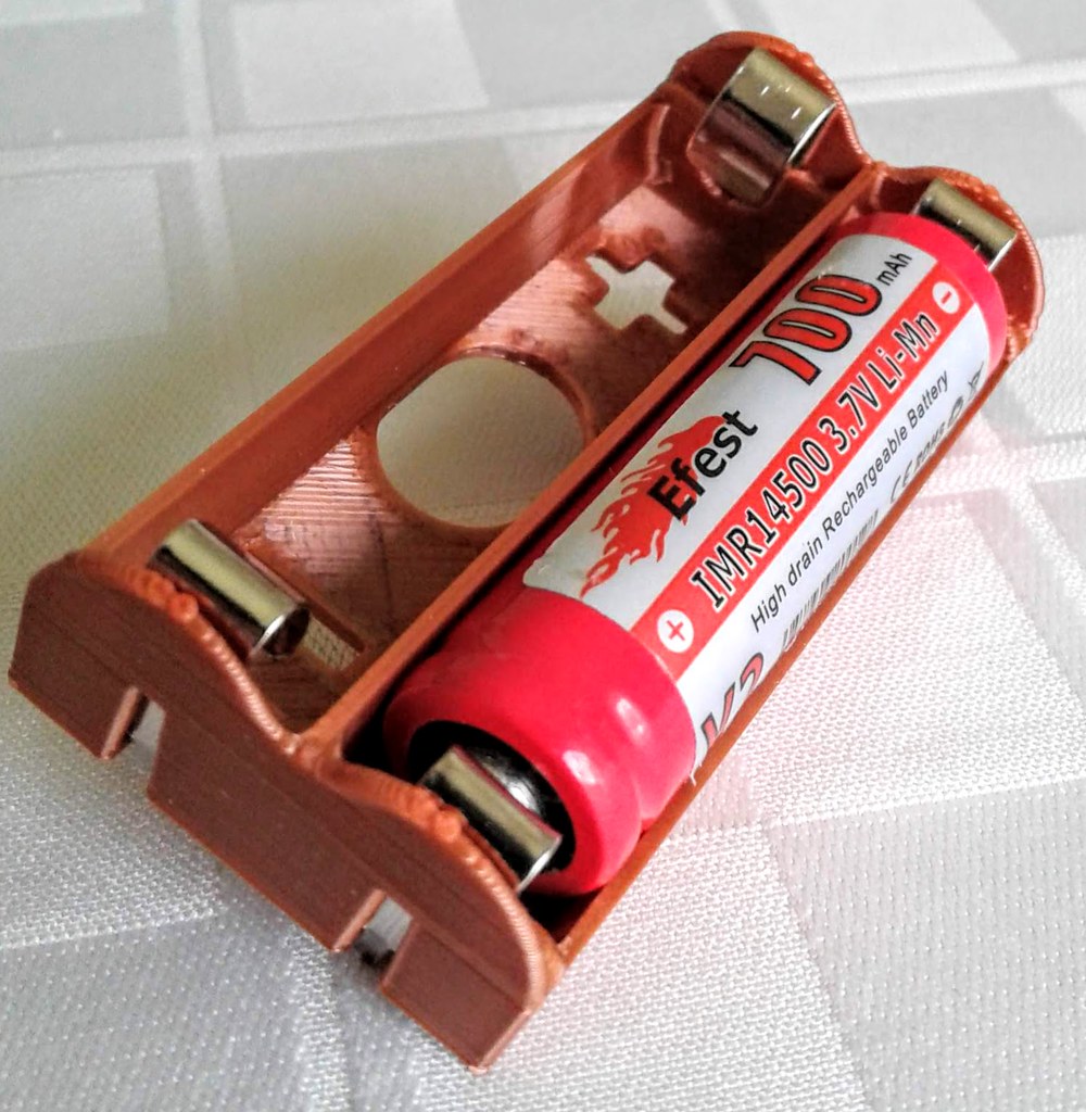
 And charge remains. When I discharged the cells to 3V each, they were at a resting voltage of 3.5V. This is well within a usable range for these cells.
 And how long could you draw using this thing? No, I'm not saying it improves the VapCap nor that the VapCap is the best vape in the world. But I am saying this is a whole new look at what the VC can do. Very versatile for micro-dosing users and power hitters alike by giving each more control over the draw - while actually drawing
 No more dipping and twirling. Just draw and bake.

 DO ANYTHING I SAY OR DO AT YOUR OWN RISK! I AM AN OLD FART THINKING OUT LOUD.
 I set out to find a way to control the power level of an IH and realized a real-time heater for the VC.

