
Here's the current configuration:
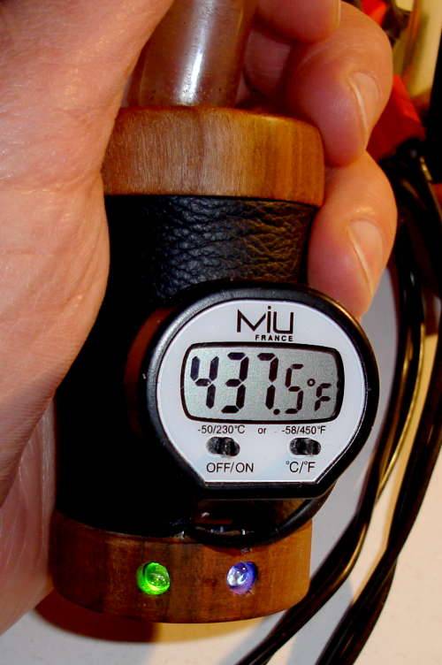
i added a bracket to hold the thermometer in place ... i hate it, it's ugly, and once the duty cycle algorithm is fixed it is unnecessary ... but until then ... it's my security blanket.
Here's some big tube (16mm x 150mm) action:
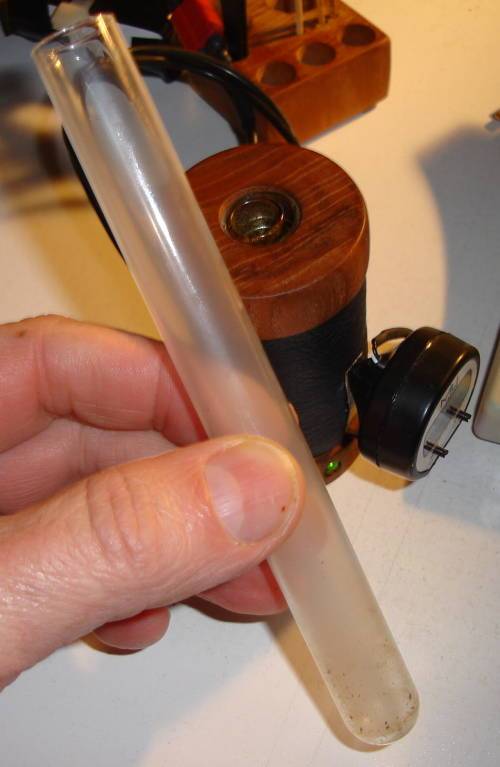
Filled with vapor:
i added a bracket to hold the thermometer in place ... i hate it, it's ugly, and once the duty cycle algorithm is fixed it is unnecessary ... but until then ... it's my security blanket.
Here's some big tube (16mm x 150mm) action:
Filled with vapor:
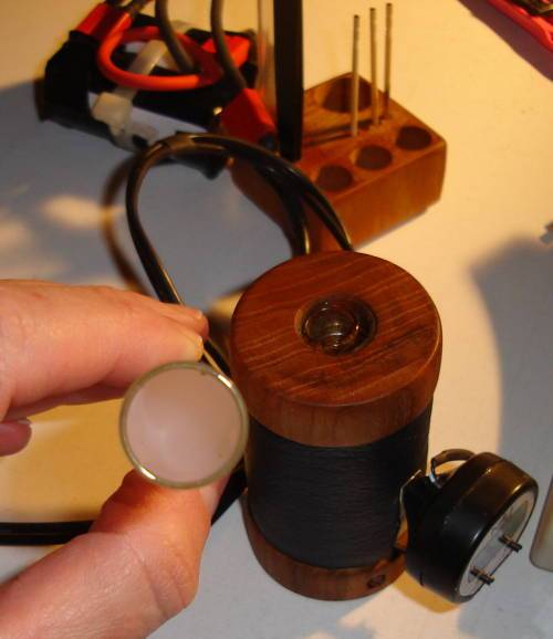
 Want!
Want!
