Discontinued VapeXhale Cloud

ZA7tphe.jpg


9MXOPNR.jpg


bb1lXNa.jpg


hqB7nUM.jpg


RMLqAOO.jpg


jk5FBrW.jpg

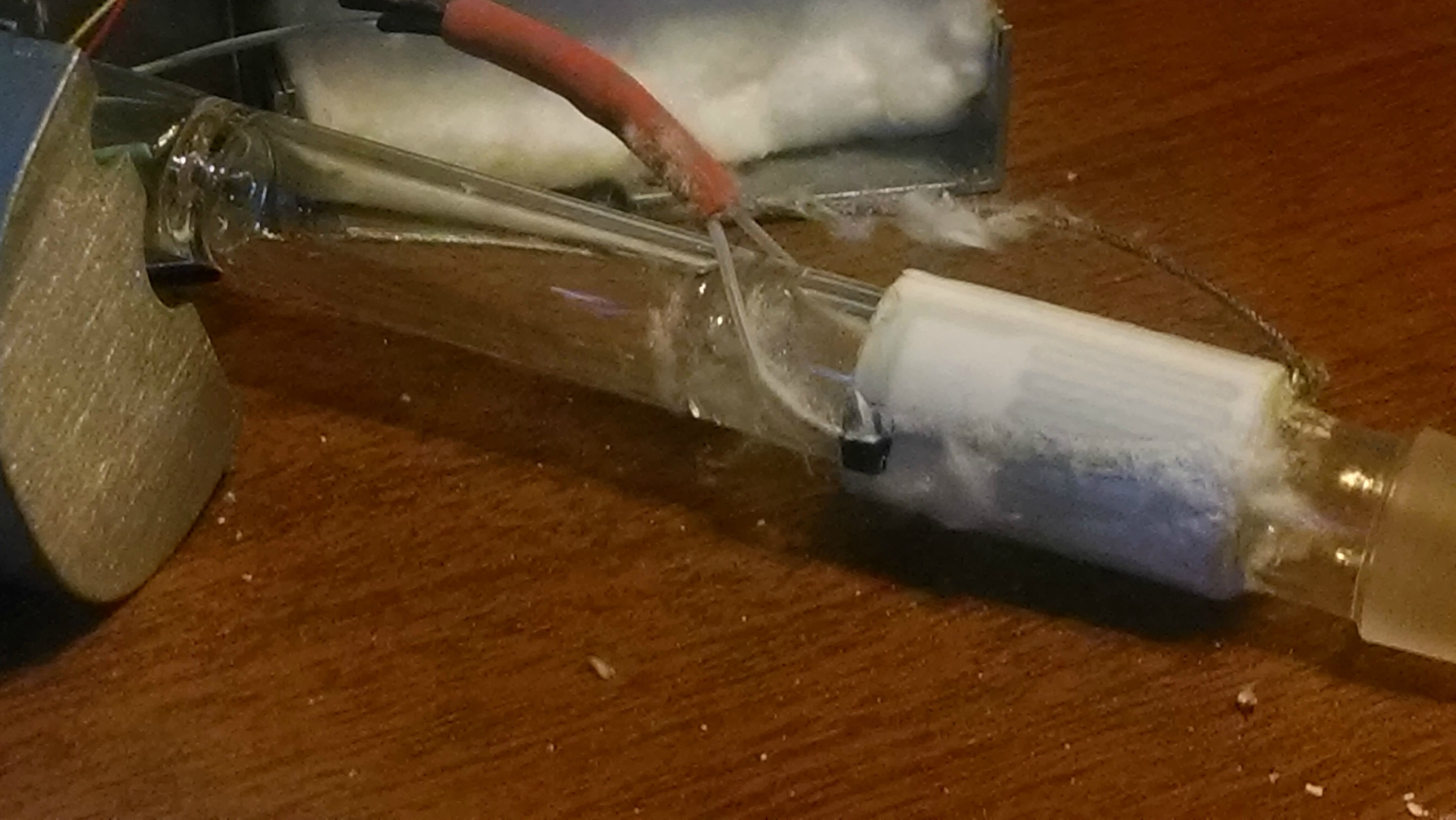
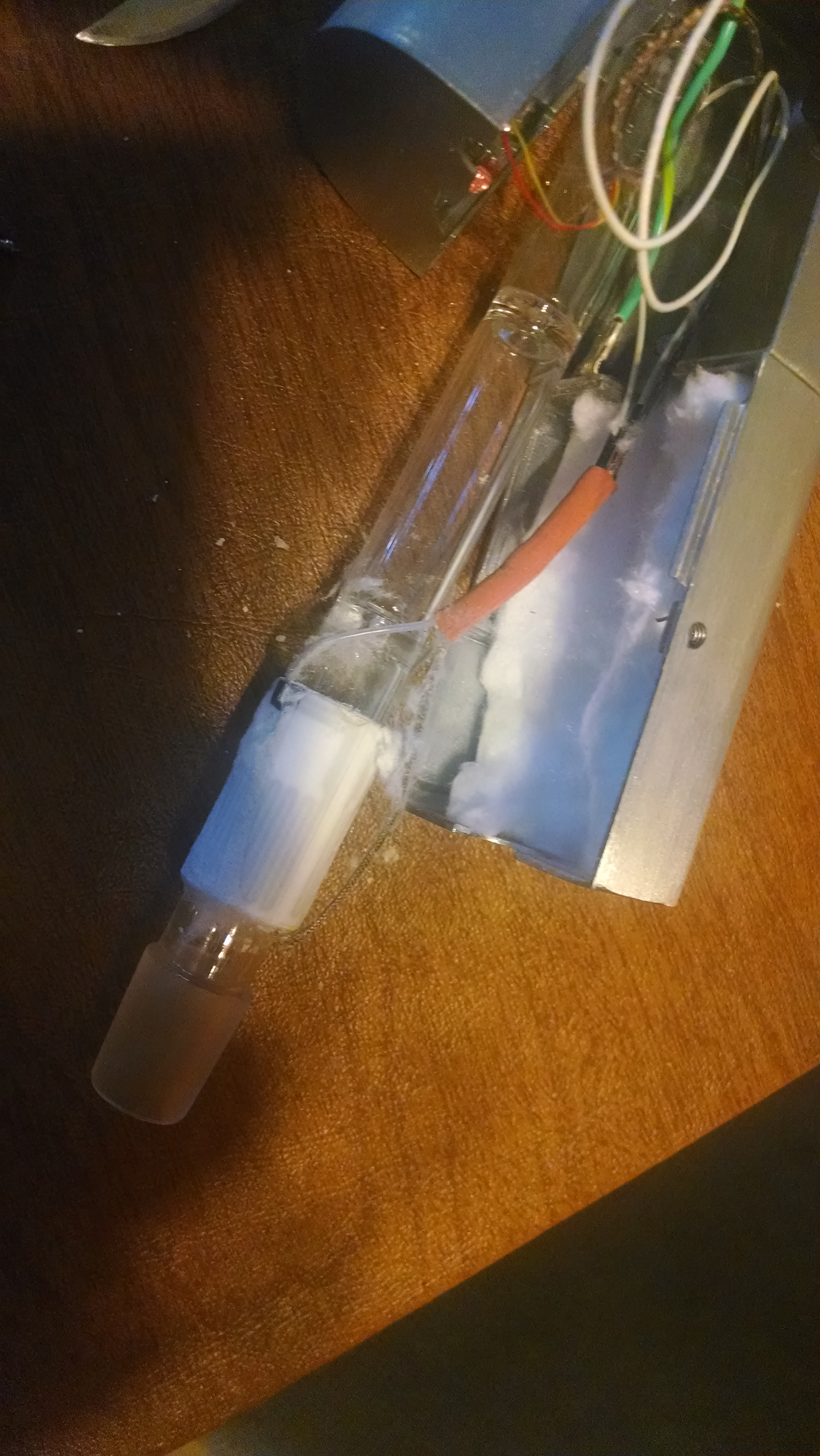
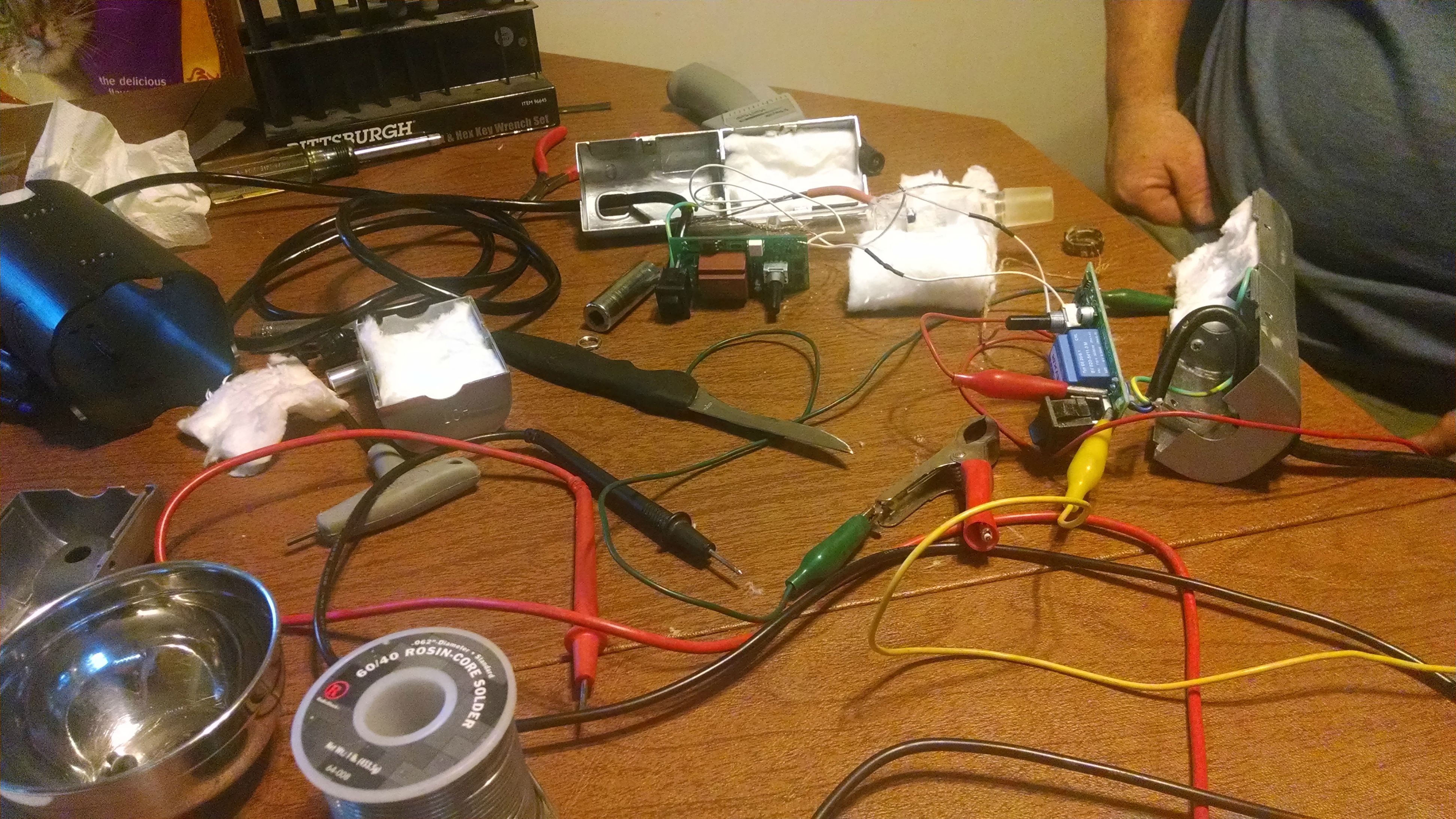
The taking apart of a flashing red light cloud

mod note: Edited to insert images correctly
 
Last edited by a moderator:

CentiZen

Evil Genius in Training
Accessory Maker
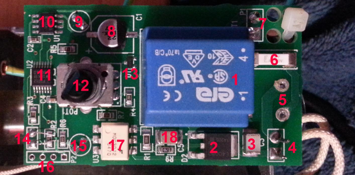
I got a little bored and impatient this weekend so I just went ahead and cracked open my own cloud to get a look at the board. For those wondering, it's not easy to get it out, and even requires soldering to be able to get to the thing. Here is a picture of the board highlighted with 18 points of interest:

AWo33Ei.jpg


  1. Isolated AC/DC Transformer 120VAC/6VDC - While the Cloud is an AC device, all the components, including the processor, are run on low voltage DC power. This transformer puts out 6V
  2. L4008D Teccor/Littelfuse Sensitive Triac 8A 400V - This is the component that makes the well loved ticking noise, as it switches open or closed, controlling the flow of power to the heater.
  3. Aluminum Capacitor - I think. It's definitely a capacitor.
  4. Contact Points for Heater Positive/Negative
  5. Front Switch Contact Points - This switch is wired directly to the ground of the board, a safe design that ensures the Cloud can draw no power while switched off. The power switch is affixed to the case as well as the board, you must desolder both legs to remove the board.
  6. I'm not entirely sure - perhaps a ceramic capacitor? Resistance is 0.03ohm
  7. AC120V Hot and Neutral Contact Points
  8. Electrolytic Capacitor - Probably the first point of electrical failure in most cases. Not the best choice for a hot environment.
  9. Red LED
  10. Low dropout voltage regulator 3.3v - This converts the 6V power from the transformer into the 3.3V power the microcontroller and LED lights will use.
  11. This is the microcontroller - but I can't identify it. I think it's Texas Instruments but none of the serials check out
  12. Panel Potentiometer - Kind of surprised to see it affixed to both the PCB and the Panel. Makes things a bitch to get out.
  13. One way diode
  14. Thermocouple leads - note the extra length after the solder joint. This should have been clipped to avoid short circuiting. Less than 2mm of distance between the points when I took it out.
  15. Green LED
  16. Programming Headers
  17. Motorola Optoisolated Triac Driver (Enamel Package) - Enamel package makes for better thermal characteristics
  18. Solid State Capacitor
I think that is pretty well everything, the bottom of the board is bare except for some spare traces. All in all I think this is a very safe and well designed circuit board with the exception of that electrolytic cap and the tc leads.
 
Last edited:

CentiZen

Evil Genius in Training
Accessory Maker
It looks like the air path where the chamber draws is a little close to the wiring, and the drawn air passes through there first. Is this true?
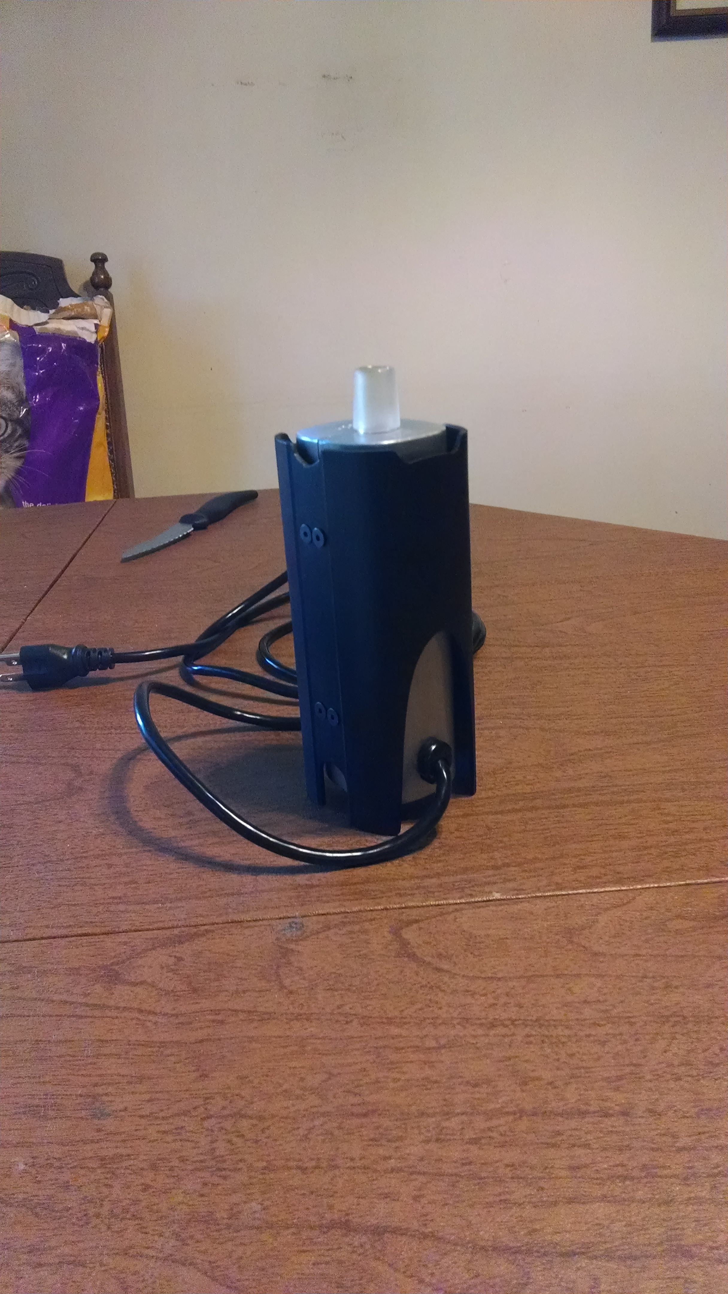
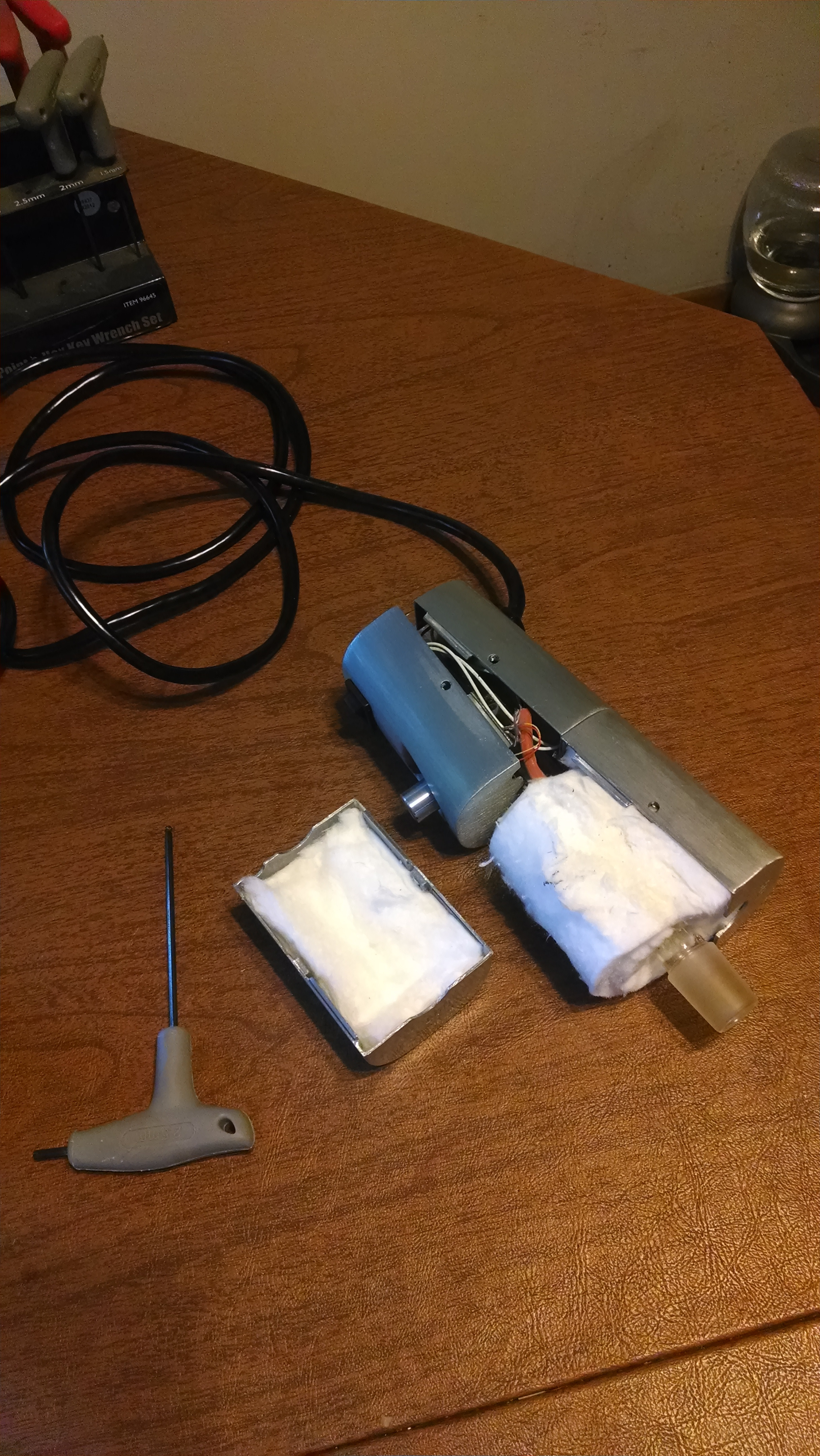
I think it's the picture making it look different - the air is draw in through the open end of the tube at the bottom of the unit. The wiring and heating element are all on the outside of the glass tubes, so there is nothing in the airpath.
 
CentiZen,
  • Like
Reactions: poonman

CentiZen

Evil Genius in Training
Accessory Maker
@CentiZen - nice work! also, does that ac/dc module get hot in operation? why do you think they used a triac instead of a MOSFET?

After some more investigation I have realized that I was wrong about the heater being fed DC power. The triac was chosen because of it's bidirectional current transmission ability, which is necessary when being used with AC power.

I can't power the board up because of the switch, but I would imagine it's a dual wound transformer which if that is the case then it won't get hot at all.
 
Last edited:

Hippie Dickie

The Herbal Cube
Manufacturer
Thanks, that explains it re:triac.

i keep trying to understand why it gets so hot on the outside ... i thought maybe it was due to the power supply being inside the case. Maybe it's just due to all that hot glass (bamboo).
 
Hippie Dickie,

oldiebutgoodie

Apostle, Church of Vaporization
I got a little bored and impatient this weekend so I just went ahead and cracked open my own cloud to get a look at the board. For those wondering, it's not easy to get it out, and even requires soldering to be able to get to the thing. Here is a picture of the board highlighted with 18 points of interest:
AWo33Ei.jpg


  1. Isolated AC/DC Transformer 120VAC/6VDC - While the Cloud is an AC device, all the components, including the processor, are run on low voltage DC power. This transformer puts out 6V
  2. L4008D Teccor/Littelfuse Sensitive Triac 8A 400V - This is the component that makes the well loved ticking noise, as it switches open or closed, controlling the flow of power to the heater.
  3. Aluminum Capacitor - I think. It's definitely a capacitor.
  4. Contact Points for Heater Positive/Negative
  5. Front Switch Contact Points - This switch is wired directly to the ground of the board, a safe design that ensures the Cloud can draw no power while switched off. The power switch is affixed to the case as well as the board, you must desolder both legs to remove the board.
  6. I'm not entirely sure - perhaps a ceramic capacitor? Resistance is 0.03ohm
  7. AC120V Hot and Neutral Contact Points
  8. Electrolytic Capacitor - Probably the first point of electrical failure in most cases. Not the best choice for a hot environment.
  9. Red LED
  10. Low dropout voltage regulator 3.3v - This converts the 6V power from the transformer into the 3.3V power the microcontroller and LED lights will use.
  11. This is the microcontroller - but I can't identify it. I think it's Texas Instruments but none of the serials check out
  12. Panel Potentiometer - Kind of surprised to see it affixed to both the PCB and the Panel. Makes things a bitch to get out.
  13. One way diode
  14. Thermocouple leads - note the extra length after the solder joint. This should have been clipped to avoid short circuiting. Less than 2mm of distance between the points when I took it out.
  15. Green LED
  16. Programming Headers
  17. Motorola Optoisolated Triac Driver (Enamel Package) - Enamel package makes for better thermal characteristics
  18. Solid State Capacitor
I think that is pretty well everything, the bottom of the board is bare except for some spare traces. All in all I think this is a very safe and well designed circuit board with the exception of that electrolytic cap and the tc leads.

Fantastic post, @CentiZen. This board looks identical to what I pulled from my first OG, except that there is one more device that I wonder may be obscured in your photo? It's immediately to the lower right of the xformer labeled "390", position R8 on my Rev E board.

EDIT: On my board the leads are cut properly. Rather sloppy that this slipped by on yours.
 
Last edited:

ictus

Well-Known Member
Hey guys,

My cloudplus died a couple months ago. I got a pretty said email from VXL saying that the company is going through hard times and nothing can be repaired for a while. Is that still the case? I see posts of people fixing their own cloud which suggests to me that it is....thanks...
 
I got a little bored and impatient this weekend so I just went ahead and cracked open my own cloud to get a look at the board. For those wondering, it's not easy to get it out, and even requires soldering to be able to get to the thing. Here is a picture of the board highlighted with 18 points of interest:

AWo33Ei.jpg


  1. Isolated AC/DC Transformer 120VAC/6VDC - While the Cloud is an AC device, all the components, including the processor, are run on low voltage DC power. This transformer puts out 6V
  2. L4008D Teccor/Littelfuse Sensitive Triac 8A 400V - This is the component that makes the well loved ticking noise, as it switches open or closed, controlling the flow of power to the heater.
  3. Aluminum Capacitor - I think. It's definitely a capacitor.
  4. Contact Points for Heater Positive/Negative
  5. Front Switch Contact Points - This switch is wired directly to the ground of the board, a safe design that ensures the Cloud can draw no power while switched off. The power switch is affixed to the case as well as the board, you must desolder both legs to remove the board.
  6. I'm not entirely sure - perhaps a ceramic capacitor? Resistance is 0.03ohm
  7. AC120V Hot and Neutral Contact Points
  8. Electrolytic Capacitor - Probably the first point of electrical failure in most cases. Not the best choice for a hot environment.
  9. Red LED
  10. Low dropout voltage regulator 3.3v - This converts the 6V power from the transformer into the 3.3V power the microcontroller and LED lights will use.
  11. This is the microcontroller - but I can't identify it. I think it's Texas Instruments but none of the serials check out
  12. Panel Potentiometer - Kind of surprised to see it affixed to both the PCB and the Panel. Makes things a bitch to get out.
  13. One way diode
  14. Thermocouple leads - note the extra length after the solder joint. This should have been clipped to avoid short circuiting. Less than 2mm of distance between the points when I took it out.
  15. Green LED
  16. Programming Headers
  17. Motorola Optoisolated Triac Driver (Enamel Package) - Enamel package makes for better thermal characteristics
  18. Solid State Capacitor
I think that is pretty well everything, the bottom of the board is bare except for some spare traces. All in all I think this is a very safe and well designed circuit board with the exception of that electrolytic cap and the tc leads.

Hello and thank you so much. This is giving us lots of directions to go in trying to fix the
one gracious cloud that we have been given. We notice on our much later cloud that #8 has
been vastly upgraded. There are now two high quality capacitors instead of one. My guess
is that the fail point was corrected.

We see that #6 is a 5 amp block fuse on our board and the part looks similar on yours.
 
MonsterWithoutBorders,
  • Like
Reactions: CentiZen

canj00digit?

All my days in a daze...
Gained a new appreciation for my FakeXhale today.
Cranked her up to 3'clock and let her sit about 5min, then took an ELB filled 3/4 with a piece of shatter
sandwhiched in the middle of the herb, let the ELB sit in the joint for about 1min and let her rip and wow what a great experience. And I didn't combust (I worried I might at 3'clock) but had complete and even extraction leaving with me coffee like ABV and no trace of the shatter anywhere on the joint or ELB.

This particular unit just seems to sit at the perfect temp at 3'clock for high temp vaping of herbs & dabs without danger of combusting.

Hope it lives longer than my last FakeXhale :D
 

biohacker

H.R.E.A.M
Sounds EXACTLY like my Cloud+. I used it at about 2:30-3:00, and it was awesome. Super fast heat up, incredible extraction and even ABV....I was SO SAD when it died. Sadly now, only an EVO can replace her, but it's supposed to be even better so I shouldn't be so sad.
 
Last edited:

PPN

Volute of Vapor
When I try to vape kief using two-caps method I crank my Cloud+ at 3 o'clock and I get many, many hits (I didn't count them but it's a lot) but hits are little except with a lot of stirring betweens hits....

Can I push up the t° on my Cloud+ to be able to vape kief in 4 or 5 big rips (at 4 o'clock....is it safe?)?
 
PPN,

biohacker

H.R.E.A.M
I don't see why it wouldn't be? I could use my Cloud+ on MAX temp and never combust...and I used bubble hash in there all the time. Crank it up and see what happens? Just be prepared to be permanently glued to the floor? :lol:
 

canj00digit?

All my days in a daze...
Anybody know any details of the kind of thermal cement/bonder that is used between the bamboo and the heater? TIA :)
 
canj00digit?,
In regard to what was being discussed 20 days ago, I have never come close to combusting in my FakeExhale Cloud+, and regularly crank it to the maximum to get a beautifully almond colored abv.

I finally got around to blowing a bag using the Cloud+, and it was among the tastiest vapor out of a bag I've ever savored. Lacking a dedicated aquarium pump like you would use with the Herbalaire, I used the Zephyr Ion set on 100F, with the pump activated. One of the lovely things about the Zephyr is that the temperature range goes all the way down to basically room temperature, and this allowed me to use it simply as a pump. Anyway, 7th floor hosing slips beautifully into the bottom of the Cloud+'s bamboo. Adding a Arizer Cyclone bowl and an elbow from the same will let you add a bag to the top, and you've just converted the Cloud+ into a bag blower. I assume that laying the Cloud on its side would be a very bad idea, so you will need to hold the unit as it is filling or devise some kind of stand.

It's definitely worth messing around with if you have any interest.
 
Last edited:

Deadhead101

I am the Vapor King--I can do anything
Has anyone messed around with putting a rubber O-ring on your Cloud like the EVO has? As of now, my Cloud isn't as stable as I'd like it to be on my glass.
 

Deadhead101

I am the Vapor King--I can do anything
I like that idea, but I might just go the easier route and simply buy a rubber O-ring similar to the one on the EVO.
 
Top Bottom