MonsterWithoutBorders
Philosophim

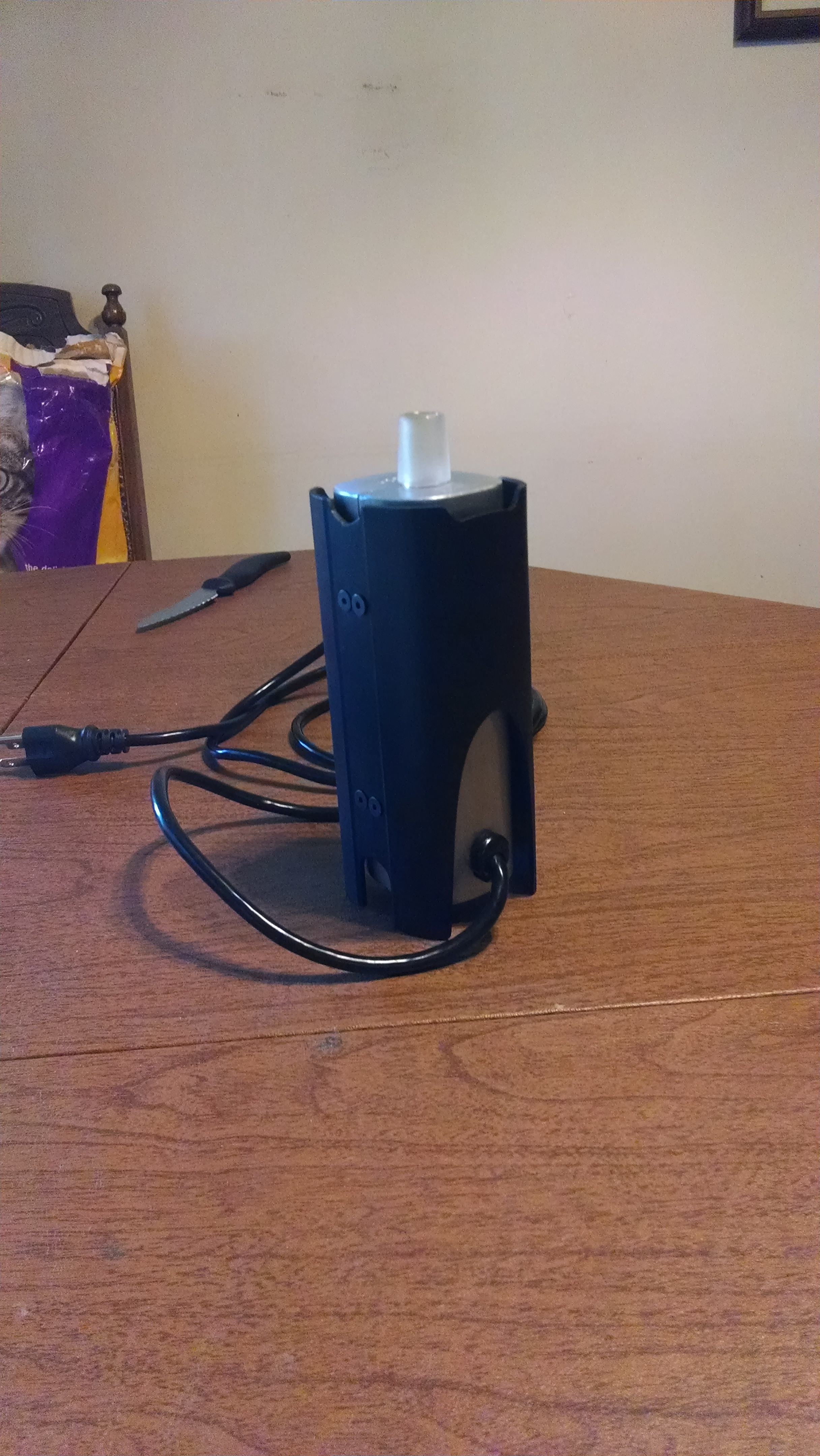
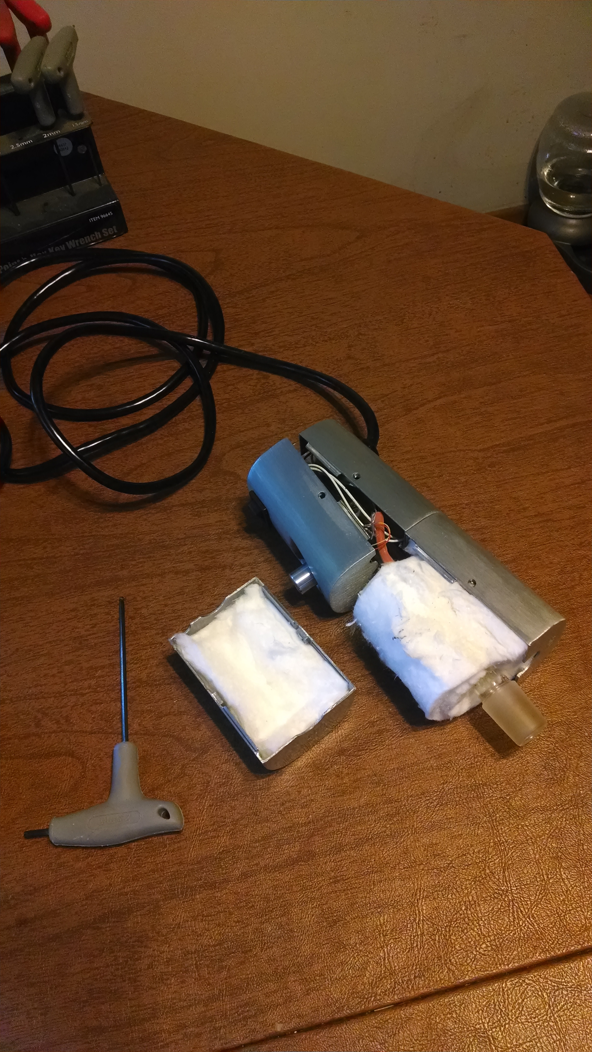
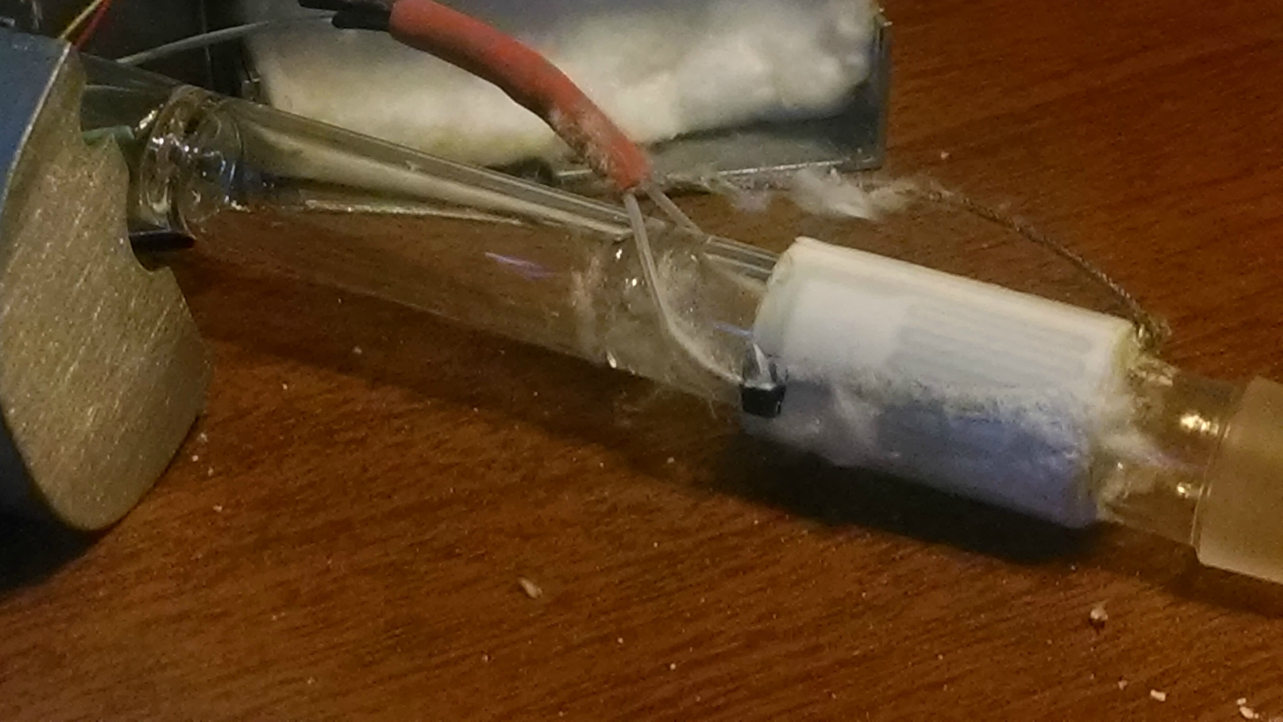
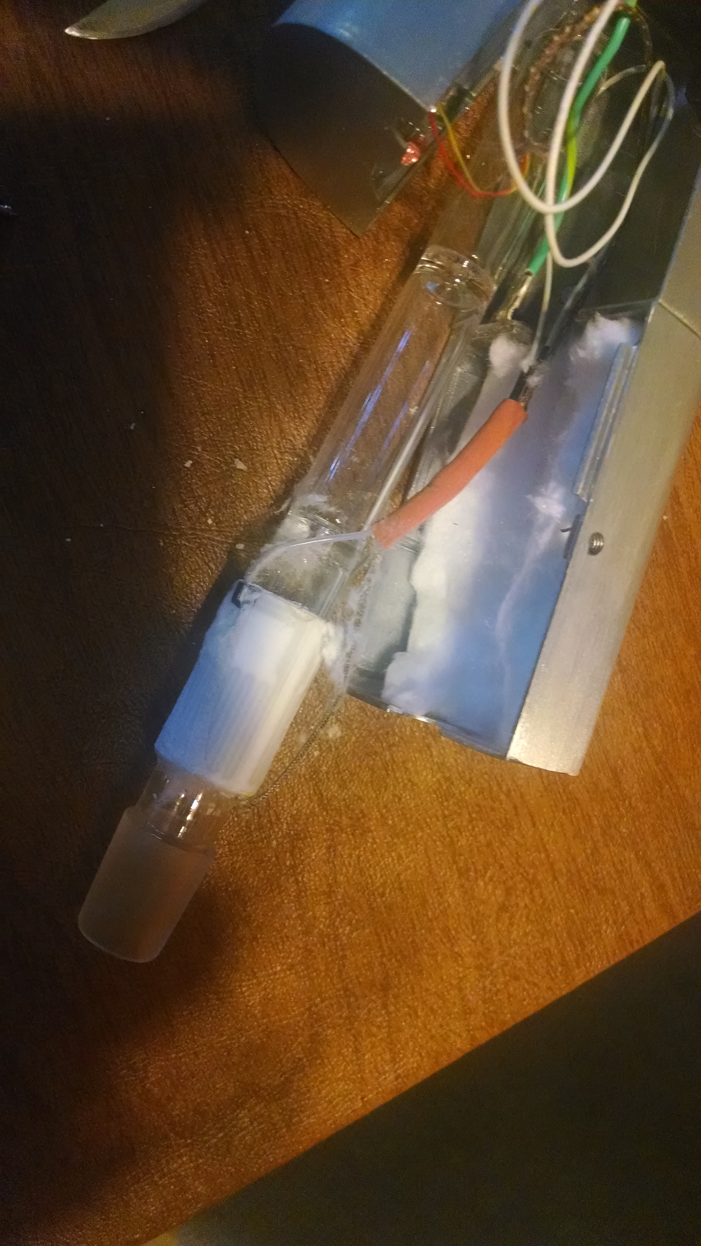
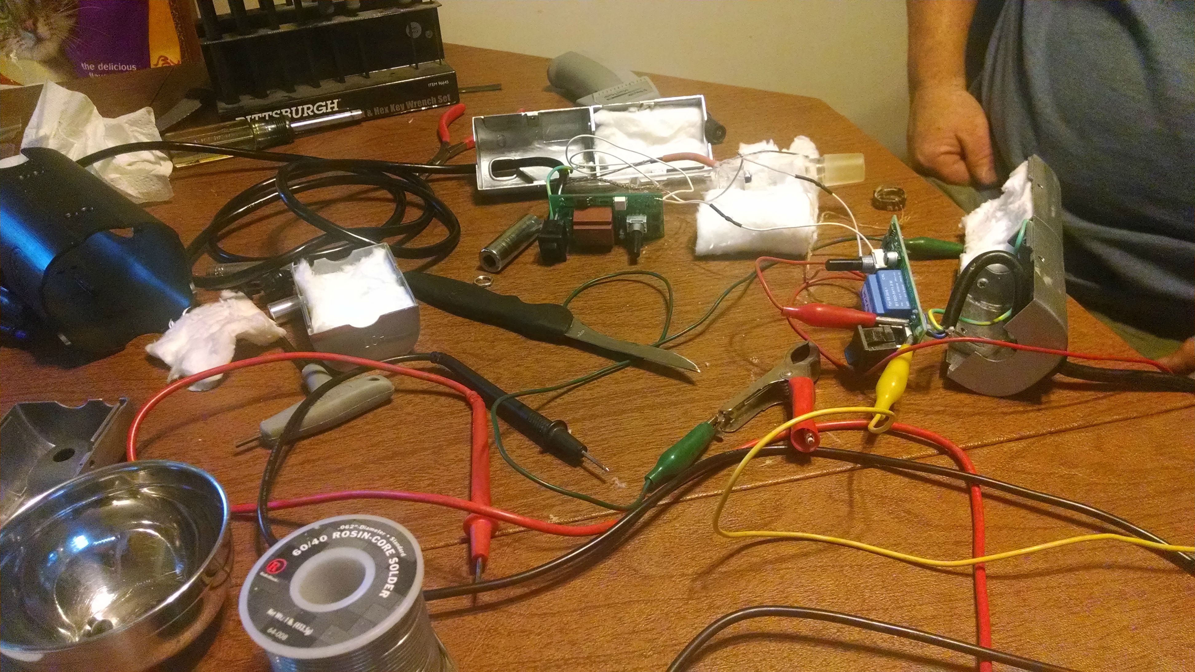
The taking apart of a flashing red light cloud
mod note: Edited to insert images correctly
Last edited by a moderator:


The taking apart of a flashing red light cloud
mod note: Edited to insert images correctly


Yes. Originally I was just going to fix the heater issue. But the only one I got has a board issue. So I am trying to understand the board and its components.Is that the plan? Attempted repair?
Post a detailed picture of both sides of the board in good lighting and I'll help out where I can.Yes. Originally I was just going to fix the heater issue. But the only one I got has a board issue. So I am trying to understand the board and its components.
I will do that this weekend. Help is truly appreciated.Post a detailed picture of both sides of the board in good lighting and I'll help out where I can.
It looks like the air path where the chamber draws is a little close to the wiring, and the drawn air passes through there first. Is this true?


The taking apart of a flashing red light cloud
mod note: Edited to insert images correctly
It looks like the air path where the chamber draws is a little close to the wiring, and the drawn air passes through there first. Is this true?
@CentiZen - nice work! also, does that ac/dc module get hot in operation? why do you think they used a triac instead of a MOSFET?
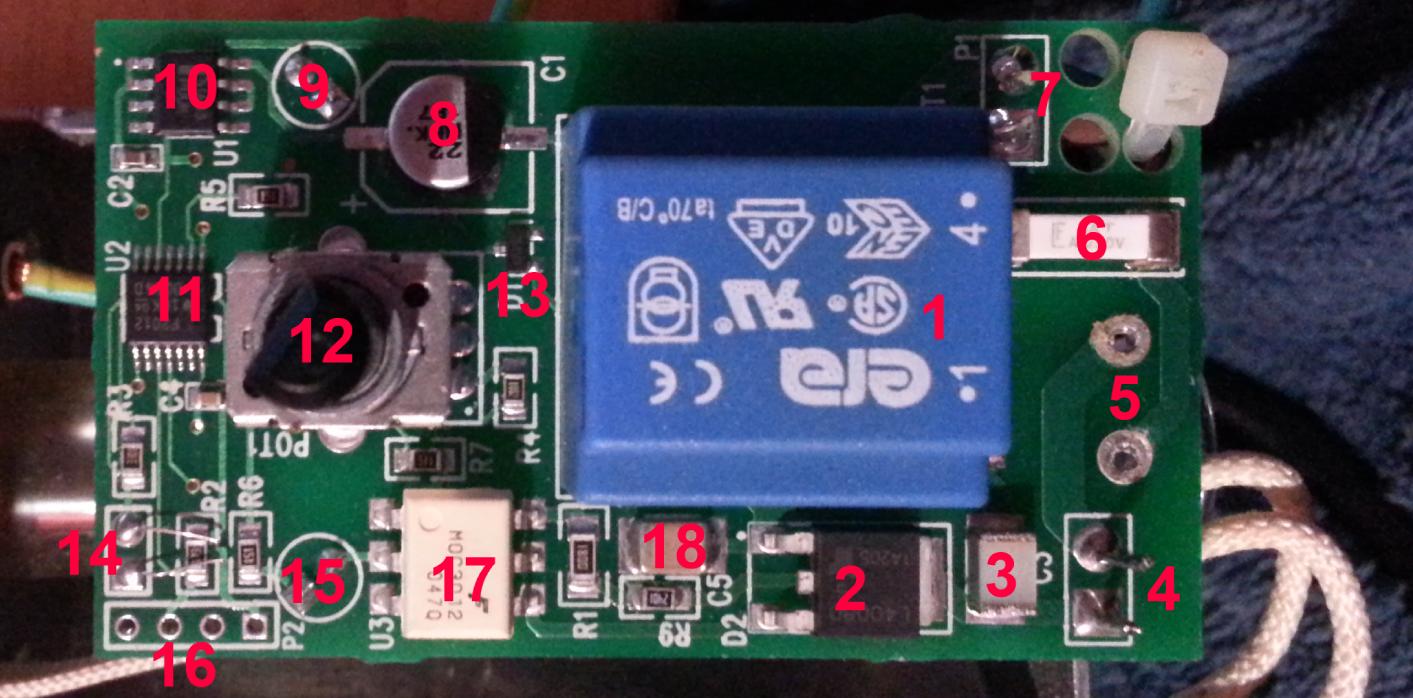
I got a little bored and impatient this weekend so I just went ahead and cracked open my own cloud to get a look at the board. For those wondering, it's not easy to get it out, and even requires soldering to be able to get to the thing. Here is a picture of the board highlighted with 18 points of interest:

I think that is pretty well everything, the bottom of the board is bare except for some spare traces. All in all I think this is a very safe and well designed circuit board with the exception of that electrolytic cap and the tc leads.
- Isolated AC/DC Transformer 120VAC/6VDC - While the Cloud is an AC device, all the components, including the processor, are run on low voltage DC power. This transformer puts out 6V
- L4008D Teccor/Littelfuse Sensitive Triac 8A 400V - This is the component that makes the well loved ticking noise, as it switches open or closed, controlling the flow of power to the heater.
- Aluminum Capacitor - I think. It's definitely a capacitor.
- Contact Points for Heater Positive/Negative
- Front Switch Contact Points - This switch is wired directly to the ground of the board, a safe design that ensures the Cloud can draw no power while switched off. The power switch is affixed to the case as well as the board, you must desolder both legs to remove the board.
- I'm not entirely sure - perhaps a ceramic capacitor? Resistance is 0.03ohm
- AC120V Hot and Neutral Contact Points
- Electrolytic Capacitor - Probably the first point of electrical failure in most cases. Not the best choice for a hot environment.
- Red LED
- Low dropout voltage regulator 3.3v - This converts the 6V power from the transformer into the 3.3V power the microcontroller and LED lights will use.
- This is the microcontroller - but I can't identify it. I think it's Texas Instruments but none of the serials check out
- Panel Potentiometer - Kind of surprised to see it affixed to both the PCB and the Panel. Makes things a bitch to get out.
- One way diode
- Thermocouple leads - note the extra length after the solder joint. This should have been clipped to avoid short circuiting. Less than 2mm of distance between the points when I took it out.
- Green LED
- Programming Headers
- Motorola Optoisolated Triac Driver (Enamel Package) - Enamel package makes for better thermal characteristics
- Solid State Capacitor
I got a little bored and impatient this weekend so I just went ahead and cracked open my own cloud to get a look at the board. For those wondering, it's not easy to get it out, and even requires soldering to be able to get to the thing. Here is a picture of the board highlighted with 18 points of interest:

I think that is pretty well everything, the bottom of the board is bare except for some spare traces. All in all I think this is a very safe and well designed circuit board with the exception of that electrolytic cap and the tc leads.
- Isolated AC/DC Transformer 120VAC/6VDC - While the Cloud is an AC device, all the components, including the processor, are run on low voltage DC power. This transformer puts out 6V
- L4008D Teccor/Littelfuse Sensitive Triac 8A 400V - This is the component that makes the well loved ticking noise, as it switches open or closed, controlling the flow of power to the heater.
- Aluminum Capacitor - I think. It's definitely a capacitor.
- Contact Points for Heater Positive/Negative
- Front Switch Contact Points - This switch is wired directly to the ground of the board, a safe design that ensures the Cloud can draw no power while switched off. The power switch is affixed to the case as well as the board, you must desolder both legs to remove the board.
- I'm not entirely sure - perhaps a ceramic capacitor? Resistance is 0.03ohm
- AC120V Hot and Neutral Contact Points
- Electrolytic Capacitor - Probably the first point of electrical failure in most cases. Not the best choice for a hot environment.
- Red LED
- Low dropout voltage regulator 3.3v - This converts the 6V power from the transformer into the 3.3V power the microcontroller and LED lights will use.
- This is the microcontroller - but I can't identify it. I think it's Texas Instruments but none of the serials check out
- Panel Potentiometer - Kind of surprised to see it affixed to both the PCB and the Panel. Makes things a bitch to get out.
- One way diode
- Thermocouple leads - note the extra length after the solder joint. This should have been clipped to avoid short circuiting. Less than 2mm of distance between the points when I took it out.
- Green LED
- Programming Headers
- Motorola Optoisolated Triac Driver (Enamel Package) - Enamel package makes for better thermal characteristics
- Solid State Capacitor


