• Do NOT click on any vaporpedia.com links. The domain has been compromised and will attempt to infect your system. See https://fuckcombustion.com/threads/warning-vaporpedia-com-has-been-compromised.54960/.

VapCap Induction Heater for Desktop and in Car Use

Pipes

Addicted DIY Enthusiast
Accessory Maker
Sometimes it seems like it is just the pads that are pushed too far because I don't get the button to click to close the circuit. When the button get stuck, I unplug my module and play with the pads with with my dynavap until I get the button to click again. could reducing the radius on the pad solve the problem?
This is actually an easy fix. There will be too much friction between the orange cushion and the glass tube. You need to fish it out with a long pin or something to get between the glass and cushion to flip it on its side, then pick it out. Now just use it like an eraser and smoothen off the highest spots on the sides of the cushion. Doesn't take much as the trick is to maintain enough friction so it doesn't fall out by itself but switch activation is clean.
You should be fine afterwards.
You can find my announcement post here: :science:
 
Pipes,

LabPong

Well-Known Member
I am on the current PSM list...but I just acquired an early PSM from another member here that had 2 and offered me their unused one from 2 years ago. (it works fine!)

I am just wondering what if any differences will a new current model have the older version may not? Heating times the same?
 

Pipes

Addicted DIY Enthusiast
Accessory Maker
The only difference will be as stated in the post above yours regarding the tact switch mechanism.
The rest should be the same. :nod:
 
Hey Pipes.

Someone shared your Google drive document with me, which led to me joining here per your instructions after joining the wait list. Don't know if it's because I'm new but I can't PM you with the PM system here.
 
Tacopocalypse,
  • Like
Reactions: Pipes

shopdognyc

Well-Known Member
Hey Pipes.

Someone shared your Google drive document with me, which led to me joining here per your instructions after joining the wait list. Don't know if it's because I'm new but I can't PM you with the PM system here.
Probably bc new just like me. Just keep being active
 

Pipes

Addicted DIY Enthusiast
Accessory Maker
I just posted in the PSM thread about an update on the new switch mechanism I announced here. So best I repeat the post.
So far it seems to be working great. There has been the odd one stick or fall out but is generally easy fixes. No reports of the silicone pad melting which was a concern but seems not to be.
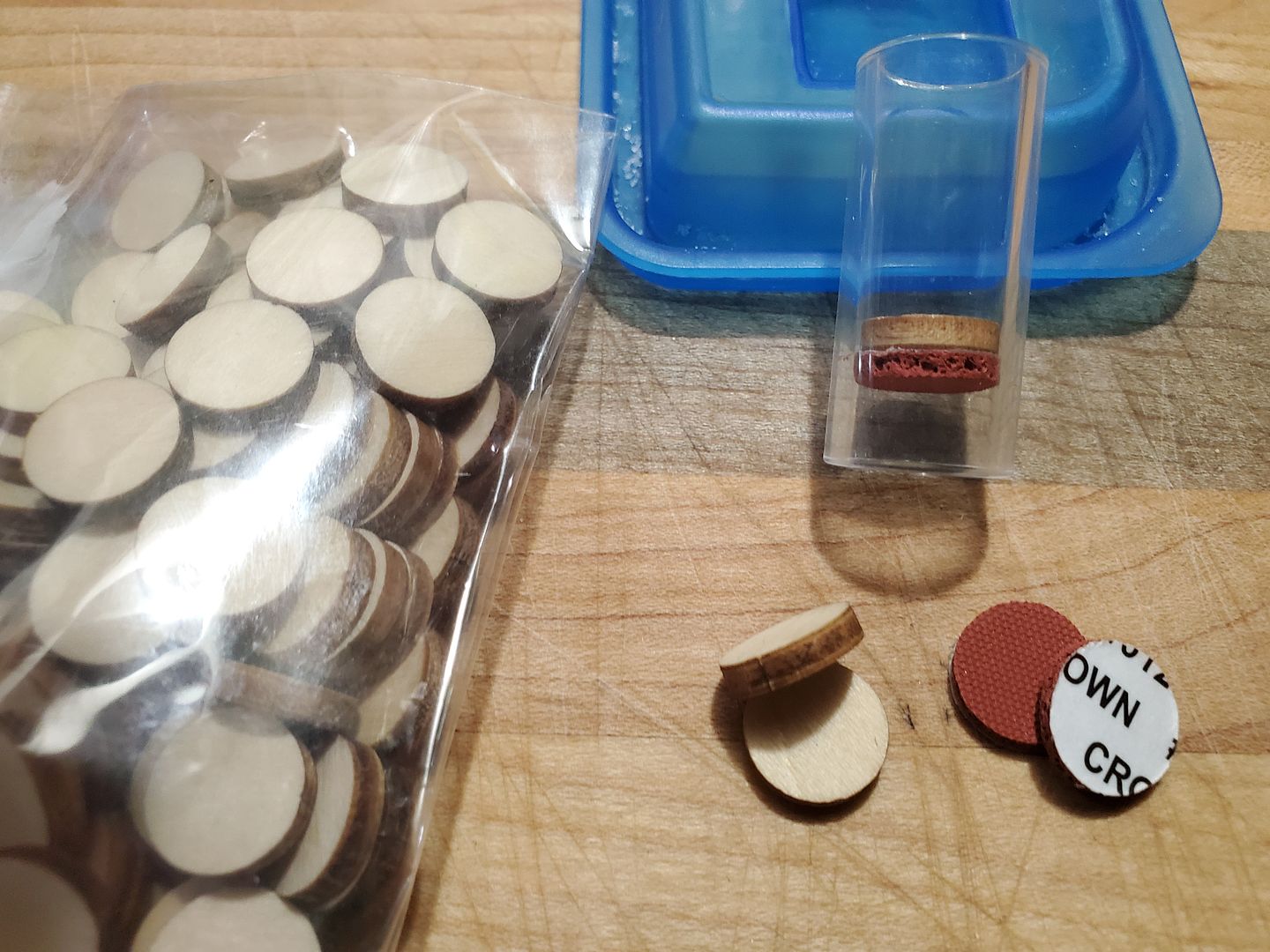
I am actually thinking of changing the heat shield to a wood/silicone hybrid but still ironing out the approach. This wood be a higher heat resistant version. Pardon the bun. However, as with my original wood shield, it would get black very quick but this is just a wood hardening process. I'm thinking of a wooden disk that fits loosely but would have a thinner low-density silicone pad slightly wider stuck under the wood disk. This would give some predictable friction which will keep the disk from sticking down and also keep it from falling out. Still throwing ideas around and might just make up a mix and match kit that the user can decide what suits their needs best. The main trick is a thin "low density, almost dense foam, high heat self-adhering disk" is affix to the main heatshield as the friction disk. I've already sourced this part along with the wood disks so won't be too long before I could do this change. :science: Unless you guys prefer it as is..? Input appreciated. :wave:
 

Mono Loco

Well-Known Member
"Input appreciated" ... maybe, maybe not! :rolleyes: I like the idea of a hybrid shield. I know it's not a valid concern, bit it feels almost un-natural, for me, to press a hot metal piece into a soft "plastic" piece ... even though I KNOW silicon can take it. I don't own any silicone bakeware ... can't embrace it yet! Having the cap contact a firm surface instead of a spongy one (again, I know the silicone disc is not mushy at all...) feels (psychologically, not just tactile) " better".

I do like the larger surface area the "same diameter as the glass sleeve" offers...over the smaller original heat shield, as it distributes the pressure onto the cap "less focused" (less dent potential), but the risk of friction causing the shield to get stuck is unsettling. It seems as if it should be free-floating. Personally, I would probably prefer a looser fit, knowing that if I were to turn the unit upside down the shield might slide out...I'd just be sure to not turn it upside down! Maybe a "plug" to stick in the chamber during transportation could prevent the shield from escaping. To keep it captive yet loose is a challenge I see.

Other than wood, which some may dislike the charring aspect of, what other shield materials are viable ... custom-sized Pyrex discs, bone/antler, graphite, PCB????

There, as usual I said a lot without saying much!
 

ezpz

Well-Known Member
Just received my PSM a few days ago. My PSM that I bought in 2018 finally bit the dust. I could just replace the battery and it would work just fine but after numerous drops on concrete, plus a few times heating without the cap, and two years of daily abuse with my 2018 Dynavap M being my only vaporizer I've owned until recently (TM rocks!) I decided to just buy a new PSM. I'm definitely glad I did. I'm very happy with the new silicone switch.
This is not scientific, just one of those medicated thoughts...... since the top of the cap is in constant contact with silicone while heating, is it fair to say that the silicone absorbs some heat from the cap, thus prolonging the heat up time before the click? I used to count 3 seconds after the click for a good dark roast on my old unit. Now with the silicone switch, no more than 1 second after the click is perfect.
I've only had my new PSM for a few days now so I can't speak on the longevity of the new switch but so far I love it. And I usually use the PSM upside down while my vapcap is on my bong.
Love my PSM. Love the silicone switch (so far). And Pipes has excellent customer service. Very happy with my purchase.
 

LabPong

Well-Known Member
Pipes....what is the stock "pad" piece you used on

the PSM? The older new PSM I received had just the metal pin the cap would contact. Was there a piece over that? I think maybe it fell off some time and the original owner didn't see this prior to sending to me.

On the aspect of the silicone/wood pad contact piece.....I am using some fairly dense 2mm silicone sheeting from my commercial shrink wrap tables. The stuff you show in the pic above appears to be much much softer than what I have.

So far this stuff works fine for me in the Caldron and the PSM. I made the piece barely fit tight so it will not fall out of the glass tube.


2mmSil.jpg
 
LabPong,
  • Like
Reactions: Pipes

Pipes

Addicted DIY Enthusiast
Accessory Maker
Pipes....what is the stock "pad" piece you used on

the PSM? The older new PSM I received had just the metal pin the cap would contact. Was there a piece over that? I think maybe it fell off some time and the original owner didn't see this prior to sending to me.

On the aspect of the silicone/wood pad contact piece.....I am using some fairly dense 2mm silicone sheeting from my commercial shrink wrap tables. The stuff you show in the pic above appears to be much much softer than what I have.

So far this stuff works fine for me in the Caldron and the PSM. I made the piece barely fit tight so it will not fall out of the glass tube.


2mmSil.jpg
Yep, that looks to be the stuff. :nod: I never used metal but it could have been the pearl vintage. :tup:
 
Pipes,

Pipes

Addicted DIY Enthusiast
Accessory Maker
That's the Rhinestone vintage. Yes, a pad should work fine. Expect some heat speed change as well. :science:
 
Pipes,

TommyDee

Vaporitor
You will find that an aluminum disk is near-transparent to RF energy. You could use an aluminum slug if you happened to have one.

I use wooden cups and it chars some wood but so what. Ever been near a forest fire? Ever do wood-burning crafts as a kid? Campfire?
I prefer wooden cups to anything else 'readily' available. This also alleviates the switch actuator heat problem. And the cup could be held inside a Teflon sleeve to protect enamel although not required. The upper o-ring will still keep the cup from falling out.

Look at the new opportunity; "How hot did you want that sir?". Being that you could set different depth cups for the properly roasted to the low-temp sentiment. Basically all that is needed is a set of shim-disks to tune the IH. I'm using a hardwood dowel and it is well patina'd in char. Seems to be quite stable even with a thin wall. Most wafting now comes from lost vape. I'd rather catch the sent of scorched wood than nearly anything else I can think of as an alternative. The proper material is ceramic but it will damage your cap. Can someone make some glass cups and do this very same thing? Yes. Wood is a better insulator so it can be thinner. Glass shims may be a bad idea. One can offer different offsets or shim the switch-side instead since there is less heat on the far-side.

Can we embrace a wooden cup as an IH coil insulator and get rid of two woes at the same time?

...and those of you who just quietly went into the backroom machine shop to check out what you can do with your wife's closet rod, I will advise; What protects the cup from degradation of the upper lip is a slight 2-degree-ish taper at the hole entrance. It is digger that does the most intense scorching. This taper avoids the majority of contact with digger. Therefore the taper should start at the neck of the cap. My dimensions were; 16mm OD and 1/2" bore. Length and depth to suit.

20200725_192536.jpg
 
Last edited:

thunderstealer1337

Well-Known Member
I decided to give up on my portable battery pack and just get a dynacup, 4th generation and lotsa positive feedback overall, some have had charging issues, but mfg seems to be very responsive and open to suggestions.

The thing that is driving me towards it is the insane amount of battery life from 18650, its like seriously 300% longer then other units
 
thunderstealer1337,

TommyDee

Vaporitor
Battery life is a real calculation I've been working for quite some time based on my usage. Do note that the Dynacup uses 2S 18650 [IIRC] and may not heat as fast. And yes, 2S 18650 at 3500mah is about 26W/H and the 700mah 3S LiPo is maybe 8W/H, so yea, 3X with margin.

I'm no lightweight and use 6-7W/H daily from my IH which is similar.
 
TommyDee,
  • Like
Reactions: Pipes

LabPong

Well-Known Member
Yep, that looks to be the stuff. :nod: I never used metal but it could have been the pearl vintage. :tup:

Pipes....the silicone you have is different. Look closely at the sides......mine has 0 pores, yours has many. Result, mine stays in place very easy and yours is much softer.


I decided to give up on my portable battery pack and just get a dynacup, 4th generation and lotsa positive feedback overall, some have had charging issues, but mfg seems to be very responsive and open to suggestions.

The thing that is driving me towards it is the insane amount of battery life from 18650, its like seriously 300% longer then other units

That is why I would not buy one from that Taiwanese seller. If they have to take advise from customers about their product design....they are not ready to be a manufacture!

Oh....2 is cool...but you should try one with 3 18650's..... SKELETOR FTW lol


Battery life is a real calculation I've been working for quite some time based on my usage. Do note that the Dynacup uses 2S 18650 [IIRC] and may not heat as fast. And yes, 2S 18650 at 3500mah is about 26W/H and the 700mah 3S LiPo is maybe 8W/H, so yea, 3X with margin.
I'm no lightweight and use 6-7W/H daily from my IH which is similar.

Yea...it will click in the normal 9-10 second fashion.
 
LabPong,
  • Like
Reactions: Pipes

thunderstealer1337

Well-Known Member
Pipes....the silicone you have is different. Look closely at the sides......mine has 0 pores, yours has many. Result, mine stays in place very easy and yours is much softer.


That is why I would not buy one from that Taiwanese seller. If they have to take advise from customers about their product design....they are not ready to be a manufacture!

Oh....2 is cool...but you should try one with 3 18650's..... SKELETOR FTW lol


Yea...it will click in the normal 9-10 second fashion.
I think your jumping to conclusions. Again it's the 4th iteration, the feedback is not how to make it function heat wise better, it's about cup style and inconspicuous designs, battery life, do realize this is the only unit I've seen having the ability from OEM design to be used upside down - complete with 2nd activation switch to be used when cup is upside down.

The product is faaaaaaaar more refined then say the USA dealer but China made alpine2020, the 2 battery charging issues was the balance charger they built in. One was solved by swapping to better name brand batteries and other was replaced due to issue with the charging balance board. I am not hearing about inconsistent heatups, smoking or melting units, and or the product glued so poorly it is already popping off, or arcing during plug ins etc.
 
Last edited:
thunderstealer1337,
  • Like
Reactions: Pipes

Pipes

Addicted DIY Enthusiast
Accessory Maker
The pads I've posted are different depending on what the use is for. The latest pad is not really for direct contact with the cap but for the friction aspect. It is LOW-density and thinner than the HIGH-density heat shield one. It also has a self-adhesive side to stick to the underside of the heat shield. This allows for a smaller diameter of a thicker shield that won't get stuck by getting twisted or by being a little too wide.
I'm leaning on the wood chip shield as I agree with statements above about wood having less heat exsorption and can withstand a lot of abuse. However, I do want to stick with the glass tube for esthetics and having it light up to let you know it's heating. Somehow, a small LED mounted somewhere just isn't the same.
I love the input guys. :love:
 

TommyDee

Vaporitor
Yes, as @Andreaerdna stated, I've been playing with different coil designs. The change I made was to narrow the diameter some and make a portion doubled up to force the magnetic lines to a more focused area. Trying to avoid it going too high and heating the stem.
You will notice it looks a little burnt. This was caused by over running it without a cool down period. The coil varnish started smoking at around 3 minutes without a cool down period. No damage but the coil did get mighty hot.


As far as, where I'm at goes, I have the main components and just awaiting some minor stuff like grommets and nice nuts and bolts. Just have to test once all together and ensure it's not overheating anything it shouldn't be. I'm mounting the coil very close to the PC board so have to really test it out.
Good news is, it all fits in the jar!! :brow: To me, getting all the parts together is a pita, but figuring out how to assemble is the most fun part.


Drilling the hole, for the power cord, is not a pleasant task. Actual, the drilling isn't bad but found heat treating is impossible. Broke 2 jars learning this. Very susceptible to heat stress. Dry grinding will have to do.

:science:

The more I read through this thread the more I realize what I've missed being a late adopter to vaping.

@Pipes - what conclusion did you come to with regard to this approach to coil management... the over-wind I mean?

20170125_163453-1_zpschlzf2xy.jpg
 
TommyDee,

Pipes

Addicted DIY Enthusiast
Accessory Maker
Man, that was so long ago. I believe they worked fine but didn't feel as efficient as the single wind and the 9-11 loops seemed to be to also hit the efficiency target the best. The conclusion was to keep the original loop count but to narrow the diameter a couple of mils.
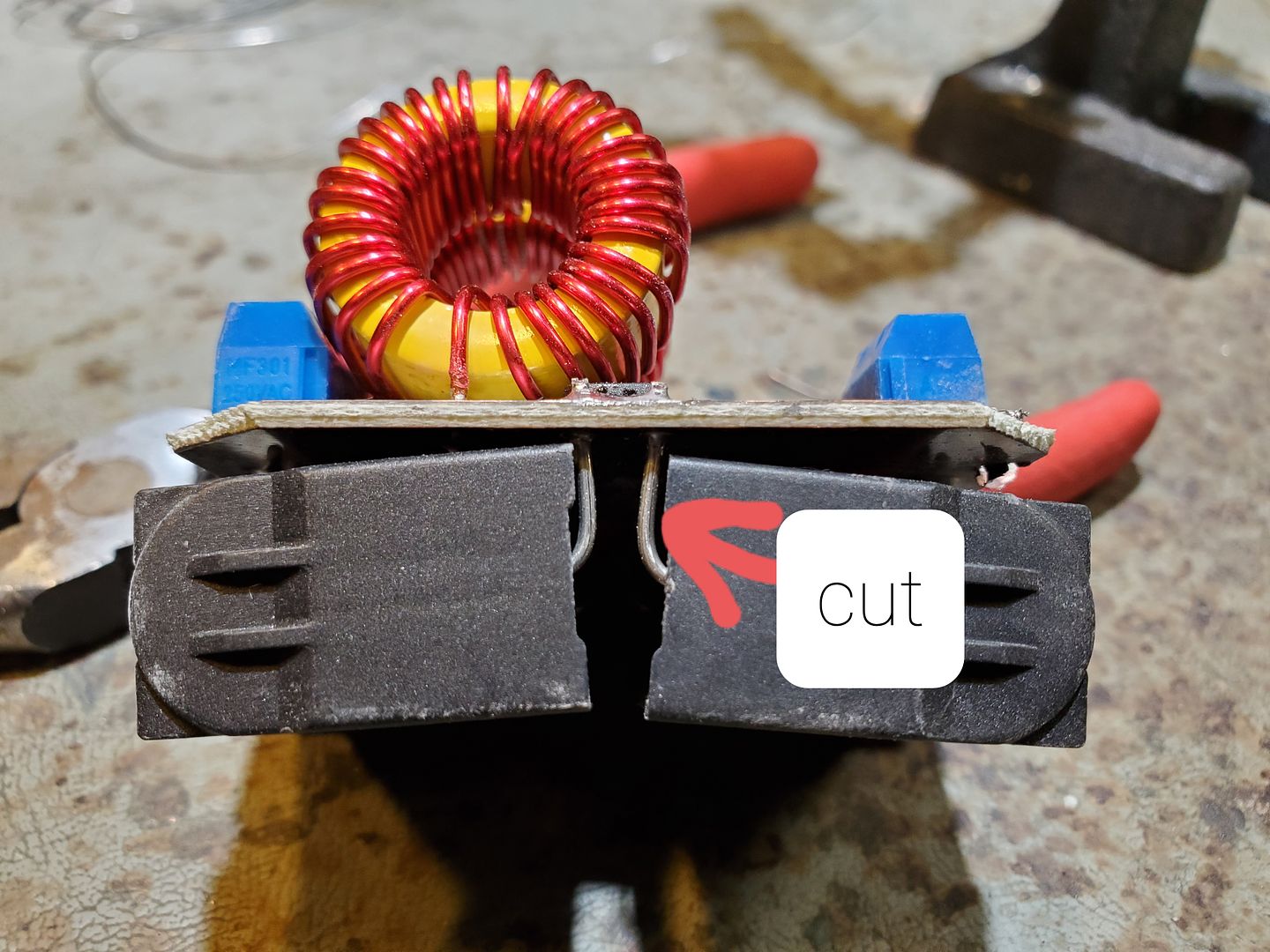
However, I never really did "in-depth" measurements but went more on gut feet in comparison to the "standard" coil. If one wants to really dig and experiment, you would also need to try different capacitors as well to match the inductance of the coil. Again, what frequency is best? Hard to really nail down. For example, removing one of the caps doubles the oscillation frequency which seems to result in less current but also longer time to click. BTW, this would also be a possible remedy for the perks who what to slow down the heating speed but if someone doesn't have soldering skills, it's a one-way endeavor by simply cutting one leg off one of the caps. If anyone tries this, please leave enough leg on the cap to re-attach to the adjacent cap leg to be able to normalize if determined it was better before type thing. Will need a soldering iron to reverse the mod. :science:
 

Pipes

Addicted DIY Enthusiast
Accessory Maker
Here you go. Cut close to the board so the lead can be bent and re-soldered to the leg beside it if needed.
Also, put some tape on the exposes leg so it does touch the other leg.
 

TommyDee

Vaporitor
Man, that was so long ago. I believe they worked fine but didn't feel as efficient as the single wind and the 9-11 loops seemed to be to also hit the efficiency target the best. The conclusion was to keep the original loop count but to narrow the diameter a couple of mils.
However, I never really did "in-depth" measurements but went more on gut feet in comparison to the "standard" coil. If one wants to really dig and experiment, you would also need to try different capacitors as well to match the inductance of the coil. Again, what frequency is best? Hard to really nail down. For example, removing one of the caps doubles the oscillation frequency which seems to result in less current but also longer time to click. BTW, this would also be a possible remedy for the perks who what to slow down the heating speed but if someone doesn't have soldering skills, it's a one-way endeavor by simply cutting one leg off one of the caps. If anyone tries this, please leave enough leg on the cap to re-attach to the adjacent cap leg to be able to normalize if determined it was better before type thing. Will need a soldering iron to reverse the mod. :science:

Thank you. Indeed I took this a bit further and I fully appreciate the balancing of the circuit. That is why I stuck with near original length and gauge [12awg]. The over-wind was more a freebie to add the additional length and therefore the efficiency, although correct, is a tuning shortcut. My end result is a 9 turn coil on the ID for its preferred diameter came to 16mm ID and a turnback of 3-4 turns wound loosely back to the beginning. The length of 20mm [average 2.2mm/turn] makes up for just about 28-30" of wire and a very favorable attachment arrangement.

The frequency change I am aware of. The phenomena is known as "electrical reference depth" when it comes to how deeply the metal is heated. Apparently, from gleaning, we should be able to operate FCC-safe within 47-100uh on the inductors. The default inductors are 100uh. I've halved that and definitely slowed the bake as well as the non-load current. In doing this, I also halved the capacitance. This is the HalfPint circuit. A center-tapped coil for positive and a single cap with a coil based on the original coil in gauge and length. Basically it becomes an 80W heater capable of more due to the FETs capability. But at 80W, the entire assembly remains cool enough to hold in your hands. The coil's wire length sets the wattage it will operate at a given voltage. Since that is a range for battery power, it is a lot more demanding to get it right. This one is tuned so when the cells need charging, you're going "what the fuck ..." as the click may never come at 9 volts, it's comfort zone it 10.5V to the module after losses. One more turn would make this a better fixed 12V voltage module or a pretty hot little heater as is. Each turn of the work coil represent about a volt in the wattage and current calculations. 12v, 11.1v, 9v. These are my scopeless tuning parameters :D

20200625_154351.jpg

However, to the point at hand, I might suggest not doing the cap-snip with both inductors in play. I tried raising my 47uh inductance by adding winds but not adding the capacitor back. The FETs got hotter than hell. I felt them through the board immediately. Better to have more cap than stored energy in the inductors. The FETs pay the price if there is insufficient capacitance. I can't risk the few boards I have to confirm this, but I might urge caution.
 

thunderstealer1337

Well-Known Member
K, well I just disassembled and moved the coil as high as I could, actually removing the o-ring and coil is in direct contact with the top lid of the caldron, is it ok for the coil to be touching something else conductive like the lid long term or really needs that silicon oring buffer?
 
thunderstealer1337,
Top Bottom