Oh crap, I only trust my XTAR chargers with my home. This is nothing to 'play with' considering their hazard potential.
First let me put it this way; charge circuits should be foolproof to the user. This should extend to the DIY guy and certainly to the guy giving instruction.
Every design has a purpose, even if its purpose is to do nothing.
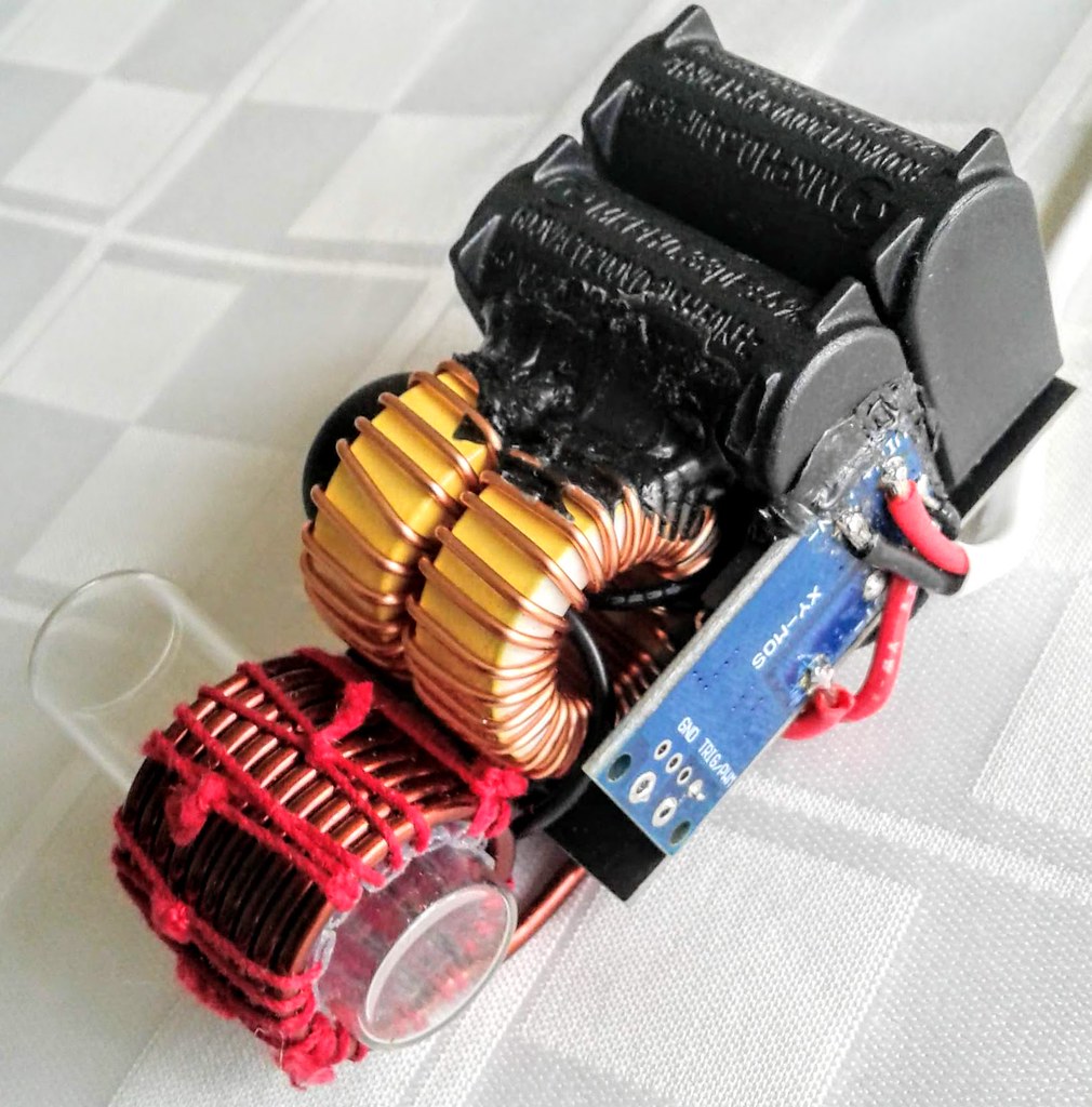
This is my an example of the level of safety I am deploying with two different IH's. Both deploy a rapid cell removal opportunity. Both can be tossed out the door within 25' of anywhere in my house. Both IH's have momentary switches rated for the job. There is no place that I cannot see imminent failure along the circuit. And I've been mindful of the appropriate wire gauge for the expected load and potential wiring catastrophe. I have a BMS that limits current and handles short circuits and I understand how it is suppose to do that. I have a source voltage for my charge circuit that does not exceed the maximum voltage of the battery pack making it quite safe and to protect the charger (wall wart) from itself, I use a 5 watt 5 ohm resistor to charge the cells slowly using the BMS on-board charger that is untested. I trust my home to this setup as well.
Count up the level of OCD statements made in this one paragraph. These are all my mitigation excuses for not completing this project into a small project box. I am still answering all those questions from a perspective of safety. My entire world is at risk of upending if these was a serious oversight.
I am not new to this part of the hobby. I've done this with flashlight tech with a very similar risk, including harboring a small stick of dynamite inside a metal tube, basically. Shit can go very bad very quickly. I, in no way, will ever say anything that will risk you, yours, or your joint domicile with a incomplete or unwise solution when it comes to messing with Li-ion cells.
Balance charging has come around to make sure each cell has it's own independent charger. You can use the balance charger board directly to your cells and use that as a charger. In that instance, using a fuse near the pack is all you need. It is preferred to use the fuse in that you can manage the fuse amperage rating rather that the 30-someodd amps the BMS will allow to pass. Basically, the BMS becomes redundant.
One thing left to decide - where to put the balance charger. If you bring the 4 charge leads to the cells from outside the IH-box, they need to be fused also. They are a potential dead short to the cell. Keeping the balance charger in the case with the battery pack makes sense for this reason. Now you just need to provide 12.6V on a CC/CV supply on 2 leads which is its own 'fuse'. This is safe to plug into the box to drive your balance charger.
The condition I am claiming is a can of worms is when you have a power supply charging the cells through the balance charger and you also have a way to put a 12.6V wall wart on the output of the BMS which activated the onboard BMS charge circuit. I don't know what those two regulator circuits would do when you have them both functioning in parallel.
And as a finish the charger circuit - if I opted for the balance charge circuit, I'd still use the same 5 ohm resistor charging wire. That is a 24/7 safe solution for me. It simply cannot malfunction and it barely gets warm.
Switches; I was looking for more reliable switches that the tactile switches to help with this bounce thing. It turns out those micro-switches are pretty good about a good solid contact force. They don't fit into my vision though. Thought that might be interesting to know.


 I have one... I'm thinking to tap into one for the IH VC to manage temperature, but one pointing up at the nail should do well to give you a nail-temp. I'll get another as a sacrificial rube to see if I can get the signal out of it to incorporate in a micro-processor. That is the next step for VC IH.
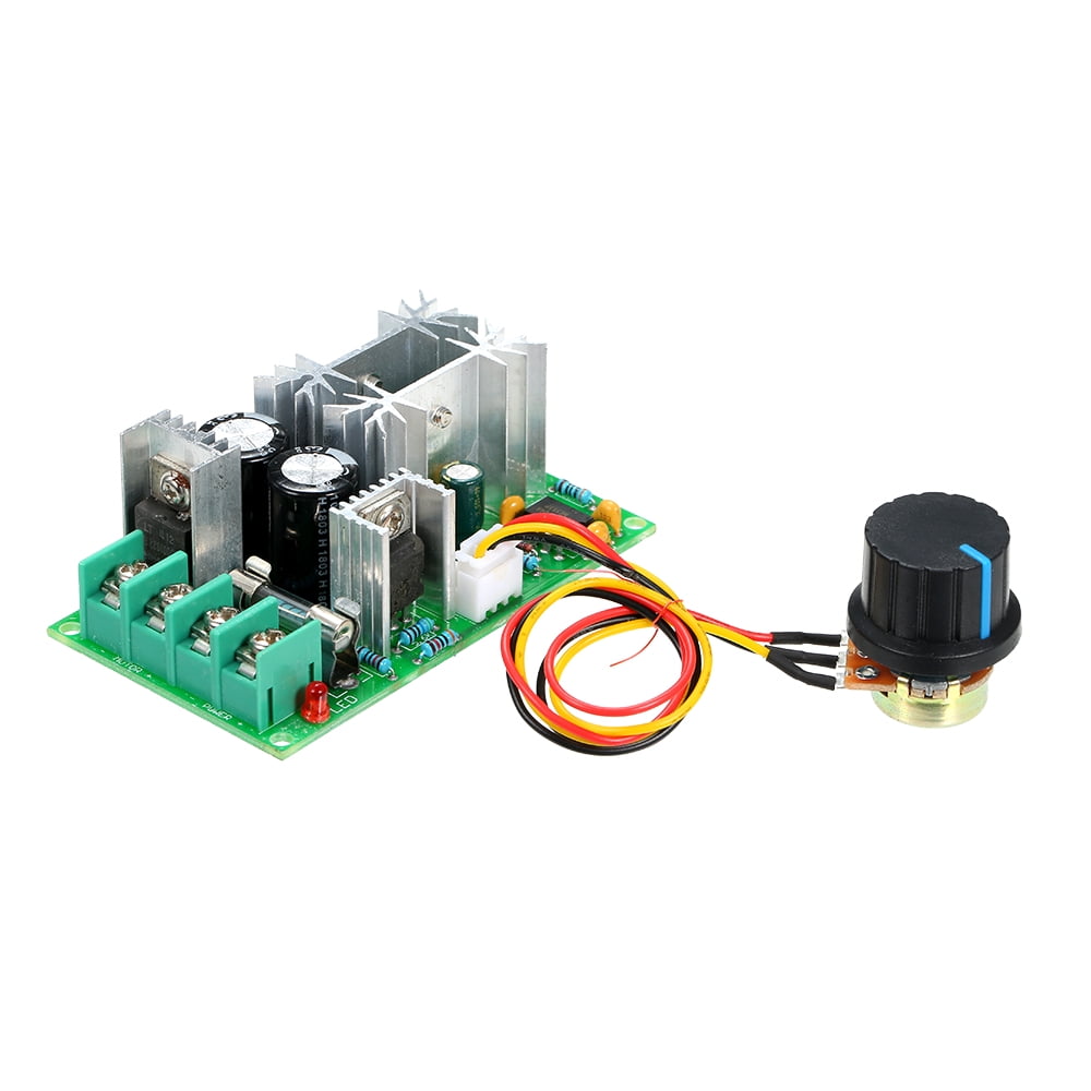
 let's not get the cart ahead of the horse. Configuration & setup for usability. Testing to make sure the thing works as desired and then enhancements. Don't we still need to test the Regulator. I need to get a couple in, one for possibly charging a small powerbrick.
 True about the regulator. I feel a lot better about it considering it has capacitors included. I don't have concerns about dirty power as much as I am about a harmonic that could drive the IH FETs batty. With a background in power supplies, this is easy to overcome. I'm just hoping to minimize bulk and wiring.