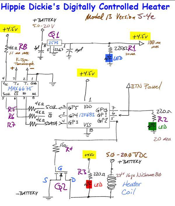
Circuit Diagram for PWM controlled heater. Jan 10, 2010
Software for PIC 12F683 and current Bud Toaster photos posted on my Windows Live/SkyDrive:
Bud Toaster project folder
Schematics
PDFs of assembly language program for 12F683 - 6 files
photos of Lady Bud Toaster - Model 13 Version 5
photos of Perfect Cube - Model 14 Version 2
Note: All images have been restored - there had been a problem with Image Shack, but that has been fixed.

Any DC voltage from 5v to 20v is acceptable. This prototype uses two A123Systems LiFePo batteries for power -- about 6.3 volts. The heater coil is 0.5 ohms, so the maximum current to the heater coil is 12 amps. The batteries can provide 70 amps continuously, 120 amps for a brief surge. This gives about 15F per second heating rate. With no current, the coil cools about 2F per second -- very asymetric, eh?
There is a control panel for user input/output. Three buttons are configured in a resister network so that each button feeds a different voltage to one Analog-to-Digital Converter channel on the PIC. Button 1 increases the setpoint temperature by 20F, Button 2 makes the current temperature the new setpoint, Button 3 decreases the setpoint temperature by 20F.
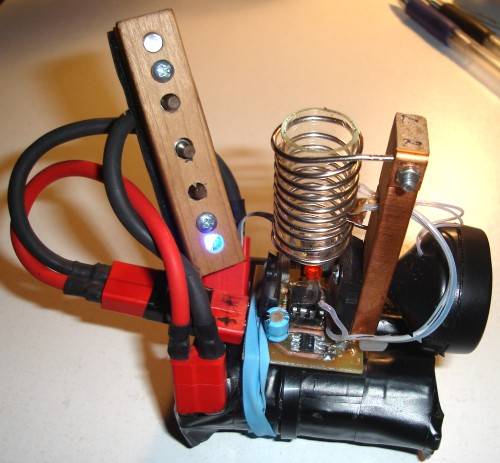
And here is the first pre-production prototype using this custom PWM heater control:
There are two LEDs on the control panel .. the top one lights when the temp is within 2F of setpoint, and the bottom one lights when power is on.

There is a red LED underneath the glass tube that lights when the heater coil is getting power.
Kinda looks like a bomb, eh?
Software for PIC 12F683 and current Bud Toaster photos posted on my Windows Live/SkyDrive:
Bud Toaster project folder
Schematics
PDFs of assembly language program for 12F683 - 6 files
photos of Lady Bud Toaster - Model 13 Version 5
photos of Perfect Cube - Model 14 Version 2
Note: All images have been restored - there had been a problem with Image Shack, but that has been fixed.
Any DC voltage from 5v to 20v is acceptable. This prototype uses two A123Systems LiFePo batteries for power -- about 6.3 volts. The heater coil is 0.5 ohms, so the maximum current to the heater coil is 12 amps. The batteries can provide 70 amps continuously, 120 amps for a brief surge. This gives about 15F per second heating rate. With no current, the coil cools about 2F per second -- very asymetric, eh?
There is a control panel for user input/output. Three buttons are configured in a resister network so that each button feeds a different voltage to one Analog-to-Digital Converter channel on the PIC. Button 1 increases the setpoint temperature by 20F, Button 2 makes the current temperature the new setpoint, Button 3 decreases the setpoint temperature by 20F.
And here is the first pre-production prototype using this custom PWM heater control:
There are two LEDs on the control panel .. the top one lights when the temp is within 2F of setpoint, and the bottom one lights when power is on.
There is a red LED underneath the glass tube that lights when the heater coil is getting power.
Kinda looks like a bomb, eh?

 wow what a rig...me likes

 which would be amazing
 . but mostly good. you are much farther along than I am, that's for sure. hooray for open source!

