The Bud Toaster - (currently: Model 14, version 3)

Stoomboot

Well-Known Member
Hi FC members,

A few months ago, a friend and I decided we wanted to build a DIY temperature controlled vaporizer. We drew up a few designs but none of them where satisfying. When we came across this tread while trying to find inspiration, we were imminently convinced of the Bud Toaster design. Although our version is far from finished I still would like to share our progressions so far.

Sooo, we started building our first prototype (witch is almost finished now). We ordered parts and started building/experimenting. I think pictures can explain this best ;).

The 'don't blow on it or it will break' setup:


A holder that is a little bit sturdier :


And the (messy) electronics as they are now:


Bigger oventube (We first ordered 12mm 'bud tubes' but they didn't fit into the 16mm oventubes we also orderd. We are now using a 20mm oventube)


And some LED madness :D


As you can see we did a few things different. We wanted to use a lead acid battery so we designed the electronics around 12 volt. We used a thinner nichrome heater coil to get more heat with less current. And we also used 7 segment displays instead of a separate thermometer.

A small list of electronics that we are using:
  • The Atmel Atmega 328P microcontroller (I had it laying around so I used it)
  • 3 seven segment displays
  • A rotary encoder
  • International Rectifier IRF3707S MOSFET
  • 0.80 mm nichrome wire
  • NXP KTY 84-130 silicone based temperature sensor
  • M74HC595B1R shift register (to drive the display)
I did make schematics but they aren't finished jet.

The microcontroller is programmed in C and uses a PID loop to control the temperature. If someone is interested I will upload the code somewhere.

There are a few thing we still need / want to do.
  • Build a new case
  • Finish battery protection (almost done, I only need to make the readings more accurate)
  • Make temperature control more stable (currently at +/- 3 degrees C)

As you can see, it is all still far away from something you can call aesthetically pleasing but its getting there :D.


We already 'tested' it a few times and we are amazed with how well it works. So a big thanks to Hippy Dick and all other contributors. It is amazing to see that people form all over the world are sharing info to make some awesome stuff (and maybe get a bit high in the process :cool:).

Happy vaping,

-Stoomboot & Co
 

Hippie Dickie

The Herbal Cube
Manufacturer
@Stoomboot - You're welcome. Very nice progress.

Do you make printed circuit boards? pretty easy if you haven't tried it. then you simply must move on to surface mount devices. although i did find that homemade pcbs were too hard to do well for the fine lines of the surface mount layout. but by then i had enough confidence in the circuit to have the boards made. having commercial quality pcbs is a real kick.
 

Stoomboot

Well-Known Member
@Stoomboot - You're welcome. Very nice progress.

Do you make printed circuit boards? pretty easy if you haven't tried it. then you simply must move on to surface mount devices. although i did find that homemade pcbs were too hard to do well for the fine lines of the surface mount layout. but by then i had enough confidence in the circuit to have the boards made. having commercial quality pcbs is a real kick.

No I din't make PCB's altough that defenitly is someting I want to do. I already had a look at some PCB manufactures and they are not that expensive.
I also tought about making them myself but because I need a duallayer PCB to route the displays I don't think that wil work out verry wel.
 

Hippie Dickie

The Herbal Cube
Manufacturer
... but because I need a duallayer PCB to route the displays I don't think that wil work out verry wel.

Do you mean two sided? You would probably need plated through holes, so yes, that would be a pita to do with bits of wire.

i mainly want to pass on the formula for a super cheap and super fast etchant solution: 2 parts of H2O2 (hydrogen peroxide) to 1 part of muriatic acid. i use a Sharpie as etch resist. be sure to clean the copper surface (i use Comet cleanser) to remove any oxide coating before laying down the pattern and etching. that's it. all i know about making pcbs myself. i tried using a copier and ironing on the pattern - i.e. transferring the toner to the copper with heat. i never mastered this and only about half the toner would transfer well (half-assed, in other words).

it took me a while to get comfortable with the pcb layout software, but after the learning curve the sky is the limit. i have all kinds of projects in mind.

best of luck on your development. i've had lots of fun.
 

stickstones

Vapor concierge
@Hippie Dickie - Would/have you ever considered releasing a DIY kit for the bud toaster that has the toughest parts done like the pcb, etc? Tom released a Pandora's Box a while ago that was a DIY Purple Days vape and I would think yours might find a following.
 

Hippie Dickie

The Herbal Cube
Manufacturer
@Hippie Dickie - Would/have you ever considered releasing a DIY kit for the bud toaster that has the toughest parts done like the pcb, etc? Tom released a Pandora's Box a while ago that was a DIY Purple Days vape and I would think yours might find a following.

i did give this some thought when Tom did that Pandora thing ... my conclusion: i would have to be out of my mind to even consider it. a box of parts wouldn't reduce the cost enough to justify the hassle of having people with non-functioning units. This vape is running at 400°F to 450°F ... i want to KNOW that it is made correctly and working properly.

however, i would love to outsource the leather case(s) fabrication - must be in USA, of course. some leather design help would also be useful. i'm training myself to do the leather work, but it is not as much fun as the electronics and programming.

some time on a 3d printer and i could make a shell that would just snap together and eliminate all the wood milling work. i could easily make dozens per day. me, all by myself.

i see too many possibilities. so my current focus is on just making 12 units of this Mod 14/Ver 3 design, integrating all the little "fixes", like the top stainless steel washer to center the oven tube and prevent the wood from checking when the hot tube makes contact with the edge of the hole in the top of the cube. (uh, oh, i'm slipping into verbal dump mode - must hit "Post Reply" stat).
 

Aeich4

Active Member
Hi, I saw your design about 5 month's back and it was this as well as 2 friend's, 1 with a dbv and another with a mflb, that got me interested in building my own vape. i've been through quite a few versions and i intend to make a thread about this and the now almost finished vape when i have the time, but for the moment i thought you might enjoy seeing my work.

parts include:
>arizer extreme Q glass set (tough bowl and elbow adapter)
>12v 50w 3D printer heater cartridge
>STP16NF06FP transistor for output to heater
>arduino pro mini 5v16mhz
>max6675 thermocouple interface
>thermocouple
>0.96" oled
>a few buttons and wires
>power supply
>12v5a wall supply
>2x18650 Samsung INR cells, rated for high current output (20a)

air path:
>glass with SS screen's and a SS and Ceramic heater

power supply is interchangeable and i intend to have pass-through and charging available simultaneously.
achieving +-3 degree temp accuracy currently.

any questions feel free to ask and i'll try and get some photo's up soon.
 

Hippie Dickie

The Herbal Cube
Manufacturer
@Aeich4 - please post some pictures - i'd love to see your vape.

i'm finally making some progress myownself ... i've got 10 pcbs populated with all the surface mount components and the pcbs for units 1, 2, 3, 4, and 5 have their coil and thermocouple, and have been debugged and tested in a test stand.

After i finish all 10 pcbs, i move on to milling some cubes and assembling these first 10 pre-production units.

oh, and is this assembly ever tedious ... you betcha. must figure out a way to reduce the labor required.

edit: finished unit 6 ... finally have a technique for forming the heater coil - uniform with sufficient precision. making a bunch of copies of the Bud Toaster is its own education.
 
Last edited:

Aeich4

Active Member
well so far i've been through quite a few versions, the first started out using glass jar's, a custom nichrome heater and a 2s lipo. one version was using hardware parts from the local shop's and looked quite interesting, but was manually controlled and overly complicated to use.

Agree completely that unit's are tedious to assemble, have to be so careful with everything.


sginte.jpg
[/IMG]
here's a picture of one of the earlier versions that was before my adoption of glass. it had a big beefy metal wand that screwed into the female piece on the side of the box, there were SS screen's either side of where you packed which was basically inside the threaded part and while it definitely did the job, it's now mostly just a testament to how much the build has progressed.

2iw1r1h.jpg

this was the first glass version with temp control, i jerry rigged that temp meter on the bottom to an arduino analog input (found the output from the op-amp of the thermocouple) that meter was in Fahrenheit (i use Celsius here in AUS naturally) however, it did work. you can see the cartridge heater and thermocouple probe inside the glass. the primary joints were 14/20mm and while i found it was a nice small pack, it definitely didn't hold enough material and in general was not the most reliable of prototypes. however the temp control did produce a stability of around +- 10-15 Fahrenheit depending on conditions.

but anyway, after lot's of work and fussy fabrication, i've now arrived at the current version which uses a glass tough bowl and elbow adapter from an arizer extreme Q.
dc0ce6f1477de2e48f06278f5264d56b.png

as you can see, i'm now working in celcius. further improvements have been made to the code since but here's a good ol screenshot of the temp stability anyway. and ofcourse the current unit. i have a screen which i'm still yet to implement, at the moment there is simply a dial to set the temp with. there are 2x18650's in there which allow for portable use (about 1-1.5 hours battery life, however i am still yet to do more testing in this area)
063fb37034f0867c1a9eeef3cc62379e.png

and a view of the back of the electronics, above the breadboard is the max6675 and below is the arduino pro mini which run's it, this photo was taken before the output mosfet, power and input dial were added and i am still yet to add the OLED, however i think i'll add is onto a separate controller as i have spares of all the other electronics, that way if something goes wrong i'll have a spare or a second unit to use for data logging.
k36ekn.jpg
 

Jimmy

Member
@Aeich4 - please post some pictures - i'd love to see your vape.

i'm finally making some progress myownself ... i've got 10 pcbs populated with all the surface mount components and the pcbs for units 1, 2, 3, 4, and 5 have their coil and thermocouple, and have been debugged and tested in a test stand.

After i finish all 10 pcbs, i move on to milling some cubes and assembling these first 10 pre-production units.

oh, and is this assembly ever tedious ... you betcha. must figure out a way to reduce the labor required.

edit: finished unit 6 ... finally have a technique for forming the heater coil - uniform with sufficient precision. making a bunch of copies of the Bud Toaster is its own education.
i am curious what your technique is for forming the coil. did you get the nichrome into a uniform spiral with repeatable results. for me, the nichrome has been a pain to wind.

Also, anyone think of using some woven fiberglass sleeves on the bare nichrome. would that help.

Lastly, just wanted to say this thread is pretty cool. I mean the next time anyone says potheads are dumb, just show em this thread. lol. I got the idea last year to make a diy vape from your thread knowing nothing about electronics. Regardless of how it comes out, i have gained sooo much knowledge on integrated circuits.
 
Last edited:
Jimmy,
  • Like
Reactions: CentiZen

Hippie Dickie

The Herbal Cube
Manufacturer
i am curious what your technique is for forming the coil. did you get the nichrome into a uniform spiral with repeatable results. for me, the nichrome has been a pain to wind...

@Jimmy - thank-you for your interest in the thread.

here is what the coil looks like after i take it off the winding jig:

picture.php


the winding jig is a 1/2" dowel with a crank handle. that bend in the end of the coil fits into a hole in the dowel. i just did 10 and they all turned out like this one. i'll try to post a pix of the jig later.

The oven tube is 5/8" outside diameter so the coil is a snug fit. i separate the loops of the coil about 1/4" so i can work the coil over the tube. if i ever do fabrication in volume i'll have to come up with a tool to help with this task.
 
Last edited:
Hippie Dickie,
  • Like
Reactions: BarnBoy

Bilbo Bagens

New Member
Hey Hippie,

I have been following your progress closely, fun to watch the progression of things. I had a few questions about your cube (making my own currently).

1. What MOSFET are you using? I had to drive a P Channel power FET with a baby NPN connected to the high rail to get the stupid FET out of the linear region where it was getting hot to the touch (even after bolting it to a 2 x 2 x 0.25" plate of aluminum). I think I have a good solution now but you mentioned you are able to drive your N channel well at 4.5V? My circuit is getting more and more complex.

2. Has your Nichrome ever cut your oven tube? My first tube got "shorter" after driving it up to about 250 degrees, nice clean cut and a nasty crack down the side. I was wondering if you have experimented with non electrically conductive thermal paste like something ceramic to better spread the heat from the wire around making it easier on the tube.

3. How are you drilling your holes in the bud tube? I have a diamond drill set for glass work, but have been holding off because I broke 5 tubes in a row on a lathe trying to cut the oven.

Lastly thanks for posting your work, been very helpful when I stumbled on this thread researching DIY vapes.

Cheers
 

Hippie Dickie

The Herbal Cube
Manufacturer
Hey Hippie,

I have been following your progress closely, fun to watch the progression of things. I had a few questions about your cube (making my own currently).

1. What MOSFET are you using? I had to drive a P Channel power FET with a baby NPN connected to the high rail to get the stupid FET out of the linear region where it was getting hot to the touch (even after bolting it to a 2 x 2 x 0.25" plate of aluminum). I think I have a good solution now but you mentioned you are able to drive your N channel well at 4.5V? My circuit is getting more and more complex.

2. Has your Nichrome ever cut your oven tube? My first tube got "shorter" after driving it up to about 250 degrees, nice clean cut and a nasty crack down the side. I was wondering if you have experimented with non electrically conductive thermal paste like something ceramic to better spread the heat from the wire around making it easier on the tube.

3. How are you drilling your holes in the bud tube? I have a diamond drill set for glass work, but have been holding off because I broke 5 tubes in a row on a lathe trying to cut the oven.

Lastly thanks for posting your work, been very helpful when I stumbled on this thread researching DIY vapes.

Cheers

1) the MOSFET i am using is Fairchild FDB8832 N-Channel, 30V, 80A, 2.1mOhm. Early on, i was not driving the gate with enough voltage, but this MOSFET has very low resistance at 4.5v. My earliest circuit had the MOSFET gate tied to the red LED (so the LED is on when the MOSFET is powering the coil), which brought the gate voltage down to 2.5 or so, and that MOSFET got very hot. This one is room temperature - i.e. it never heats up, no heat sink other than being flat against the pcb.

2) never. The heater coil doesn't even dimple the glass ... 450°F doesn't get close to melting temp for borosilicate. Are you using borosilicate glassware?

re: ceramic paste. Yes, i did play around with such like. wrapped the heater coil around the glass and then put a 1/4" thick layer of ceramic paste over that.

i abandoned this approach early on. pain in the ass to work with -- i would never be able to do production volume. Plus it took a LOT longer to achieve stable vape temp - but this could have been the simple ohms law/log style vape design as the cube was then. i thought it would add thermal mass for less temp drop with a toke. it didn't and the temp drop that occurred required more time to recover (vs. just the glass oven).

and the ceramic isn't needed for better heat distribution - i just space the loops of the coil close enough to get an even heat distribution (about 1/10"). the boro conducts heat quite well over short distances.

3) to drill the holes in the end of the vial and draw tube, i use a dremel (in a stand, like a mini-drill press) spinning at 10k rpm, with a 0.75mm diamond drill bit, with the glass submerged under about 1/4" of water for cooling. I put a perforated template over the end of the glassware so the bit doesn't wander - just a piece of thin copper foil (which I had on hand) with the hole pattern punched through. the bit snaps after about a dozen or so drilled holes. i buy a dozen bits at a time.

before i went to india for the oven tubes, i used a hand-held glass scoring tool (used for cutting window panes, etc.). i have a jig that holds the cutting tool against the tube, so i just rotate the tube a dozen times against the cutter, then torch the score for about 60 seconds (using a BIC), wrap with damp cloth, and snap at the score. i have a glass polishing wheel for when the edge is jagged (which is usually). i buy tubes by the case - 72 per case.

you're welcome ... thank-you for your interest in the thread. and keep on vaping.
 
Last edited:

andrewburgess

Well-Known Member
@Jimmy - thank-you for your interest in the thread.

here is what the coil looks like after i take it off the winding jig:

picture.php


the winding jig is a 1/2" dowel with a crank handle. that bend in the end of the coil fits into a hole in the dowel. i just did 10 and they all turned out like this one. i'll try to post a pix of the jig later.

The oven tube is 5/8" outside diameter so the coil is a snug fit. i separate the loops of the coil about 1/4" so i can work the coil over the tube. if i ever do fabrication in volume i'll have to come up with a tool to help with this task.


the picture of the coil looks like the coils can touch each other. is the wire stiff enough that once the individual coils are separated they stay put?

EDIT: i see you answered this on the previous page (maybe i should read front to back?). no delete button so i'll add this. sorry for the noise.
cheers
 
Last edited:

Hippie Dickie

The Herbal Cube
Manufacturer
to answer your question: yes, the loops stay separate when attached to the copper coil clips. the top end of the coil makes a 90° bend and is 1 1/8" long so the loops are forced to be separate. That's one reason why i switched from 28awg to 16awg, so the coils would stay in position - plus the resistance is much less at 0.25 ohm per foot, pulling massive current (12 amps) to hit the vape temp faster, i.e. <30 seconds with a full charge.
 

yayvape

Member
Hows it going Hippy?
Thought of something the other day, did you ever experiment with a thermistor instead of a thermocouple? Would be far cheaper as its just using a single adc pin rather than a MAX6675. Glass bead thermistors are used in 3d printers that PID regulate anywhere from 50 to 300°C. http://reprap.org/wiki/Thermistor
 

Hippie Dickie

The Herbal Cube
Manufacturer
@yayvape - yes, i did look at thermistors in the beginning, and i don't remember exactly, but i think at the time they didn't have the right characteristics - maybe it needed more support parts (op amp, maybe?) or didn't have the range i needed.

A thermistor is usually more accurate than a thermocouple, but thermocouples can handle higher temperatures and are linear.

maybe it was this characteristic. thanks for that link, but gosh that looks complicated to work out the details. the MAX6675 takes care of all that stuff.

i think the MAX6675 is the perfect component. The k-type thermocouple is the expensive component, at $6 each when i have to buy them. i need to get a spot welder and make my own, and get the price down to $0.15 each. The MAX6675 would be $4 in 1000s quantity. These costs are down in the noise, i.e. not what sets the $750 price.

thanks for the comment/question ... it's nice to revisit some design decisions.

For example. i had the opportunity to use a PAX in June, and the experience was quite enlightening. i have made some fundamental shifts in my thinking about the battery pack. and that change has rippled through other aspects of the design -- particularly the case. and i've decided to add a pcb to implement a LiFePO4 charger. and this changes everything.

So a single 12v 5a ac power supply will be included in the package to either charge the battery pack or run the cube directly. it's a universal power supply, so already international power grid compatible (120-240vAC, 50/60 Hz input) and passed by all the regulation agencies world wide.

Removing design constraints is a liberating process, even if it does feel like i'm floating adrift, at times.

And, while the PAX is nice for what it is, i much prefer my cube.
 

yayvape

Member
Yeah the thermocouple and digitizer would make up a large chunk of the electronic component cost, and some build time to make the thermocouple but when you are hand building vapes, component costs are nothing ;) still, if you were to mass produce the boards and outsource manufacturing, it's significant!

Temperature range shouldn't be an issue, these are good to 250C http://www.digikey.com/product-search/en?vendor=0&keywords=495-2125-ND
They are non-linear and you need a lookup table to convert the ADC value to temperature. But you can sample at KHz rather than waiting 250ms per temperature sample. and they have a glass bead which means it doesn't matter if they touch up against the heater coil. They only need a single resistor to work (makes a voltage divider.)
I will try one out when I rebuild my bud toaster clone, when ever I get around to buying new glass vials. gah, hardest parts to source. last time i bought 20 test tubes and ended up with 2 useful vials.

Oh another point you might appreciate, looks like that fairchild FET is getting pretty old by MOSFET standards. The gate charge is huge.. Gate charge affects how long it takes to turn the fet on, because it's like a capacitor on your gate, which takes a while to charge up to the threshold voltage. and while it is charging, power is wasted as the FET is in it's linear region. Compare with something like http://www.digikey.com/product-detail/en/CSD17311Q5/296-27625-1-ND/2345381 cheaper, faster, smaller.
Thats the trouble with taking years to develop a product, your parts become obsolete :p the MAX6675 is not recommended for new designs too, replaced by MAX31855 although it's not marked as obsolete yet, the new one is just cheaper.
 

Stoomboot

Well-Known Member
Hi all,

I would like to report on some progress from my side. There are a few things I did.

Fist of all, I hammered together a new case :D. I thought it would be cool to put aluminum foil on the inside trough I don' t think it really helps with anything. This case holds the heat much better then the old one I used, which was made out of bend floppy drive enclosures (ghetto FTW).


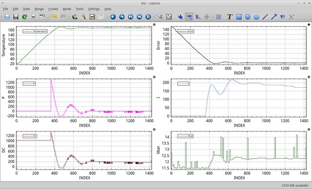
Then something more exiting, I completely rewrote my code. It is now much cleaner and easier to read. While I was in a solid coding trance for a few days, I wrote code to send things with the usart build in to the microcontroller. This was really helpful with debugging and I realized that it was something I should have done much earlier. The serial output also enables me to make cool graphs like this (the setpoint was set at 170°C) :


With this new data I desisted to removed the derivative element from the PID algorithm since it wasn't really doing anything and only made things unstable. The temperature now stays within +/- 1°C of the setpoint.

As you can see in the bottom right graph the software can now read the battery voltage so it can stop heating when the battery is getting low. I solved the inaccuracy and instability of the readings I was having by changing the voltage divider ratio and taking the average of all readings done in 1 second.

Currently I am in the process of designing a pcb. The board will be 75x45 mm and will be fitted in a small project box. The displays and rotery encoder will be on the front and the rest of the electronics on the back. Here are some screenshots of the design in Kicad. This isn't a finished pcb yet, there are still a lot of funky traces I have to clean up.


When I am done with the design I will order all the parts so I can verify the footprints. When I am confident it will all fit I will order the pcb.

So that was it for this post. Hopefully I will be back soon with pictures of the pcb' s :)

Happy vaping,

- Stoomboot
 

Hippie Dickie

The Herbal Cube
Manufacturer
@Stoomboot - it is really great to see your progress ... thank-you for sharing the pictures and info.

And, on a similar note, i have made some progress, too ... actually, a mystery solved.

i have been trying to figure out for the longest time why the upstairs Cube seems to work so much better than my desktop Cube. and for the longest time, i just wrote the difference off to a mistaken subjective impression.

However, i kept thinking about the difference and i have considered a number of possible causes:

difference in the air gap between the oven tube and the vial:
i find wide variety in the dimensions of the glass test tubes and vials -- knowing nothing about it, i had a mistaken idea of how consistent machine made glassware turns out to be. Instead, it is not like milling metal. However, i had decided years ago, after using many different versions, that the size of this air gap did not make a noticeable difference. But since i have a box of Gujarat oven tubes (15mm test tubes, with custom length of 1.375") i have played with swapping oven tubes to get a tighter tolerance. all to minimal change in performance.

different temperature control algorithm:
Okay, the upstairs Cube is the previous version - earlier pcb - which actually uses thinner copper traces, hence somewhat less current flow (but actually i think current limiting is happening before it gets to the pcb). Plus it has an earlier iteration of the software - may still be using a calculation rather than table lookup (current version) for setting the PWM duty cycle. Again, should only affect stability by +/- 1°F or so.

different BBQ thermometer probe placement:
can i be sure the probe is making tight contact with the outside of the oven tube? or even, is it the same sloppy or tight arrangement in both Cubes? i am trying two different probe mounting techniques, but to me they look to be and should be equivalent.

So, a mystery to chew on when i need to flog myself (raised catholic, eh?)

Then just two days ago i happened to notice the lip of the glass vial i was using with the desk Cube - really notice it. And i finally noticed there was a glass defect that caused the rim of the open end to not be flat, i.e. it would not make a complete seal with the draw tube. Again, this gets back to my bad assumption about the perfection of the geometry of the glass vials, so i had always assumed a perfect fit between vial and draw tube.

So i tried filing the edge of the vial to get closer to a flat smooth edge, and that did help a bit. but further testing by blowing and sucking air showed that there was still a small gap, and i could not get a partial pressure from the vial into the draw tube. so, i'm like wtf???

So i searched around in my glass vial drawer and found a virgin vial that would pull a partial pressure. i only had to add the notches in the edge of the bottom end. And then test. omfg! No, that should be OMFG!!!!

another mystery solved. This renews my faith in the design, and well, the whole project.

grinding the edge of the vial flat is going to add another processing step, but this is incredibly important. i might as well look into getting some fritting grinders and really make a tight seal between the vial and the draw tube. if there has to be a processing step anyway, make it count, eh?

also, i've got a new approach on the case ... just ideas at this point, so i need to spend some time in the shop for a reality check.
 

Hippie Dickie

The Herbal Cube
Manufacturer
so i think i am finally closing in the case design and interior configuration (version 34b), and since the power cell pack will be fixed (i.e. non-removable), i can shrink the size of the case about 1/4 inch, so that got me thinking ... i don't really like the way the power connector juts out from the back of the cube (when unplugged, i.e. power cable not attached), so i got to wondering if the Deans plug can be recessed, and ideally, soldered directly to the pcb. and the answer is ... YES


picture.php


And, boy oh boy, does this provide a cascade of benefits - both for construction and reliability ... actually removing another observed (minor) point of failure, where the Deans connection to the pcb becomes intermittent due to the screws not creating a truly gas tight attachment. fucking problem solved!
 

Stoomboot

Well-Known Member
Looks great Hippie!

Do you think the PCB traces will hold up after a lot of connecting and disconnecting of the deans plug? I figure there will be a lot of stress on them since deans connectors (at least the ones I have) are very stiff.

I also have a small update myself: I ordered my PCBs a few days ago, they should be here in a few weeks :D.
 
Top Bottom