Induction heated e-nail with arduino closed loop temp control

hardboiledfrog

tinkerer
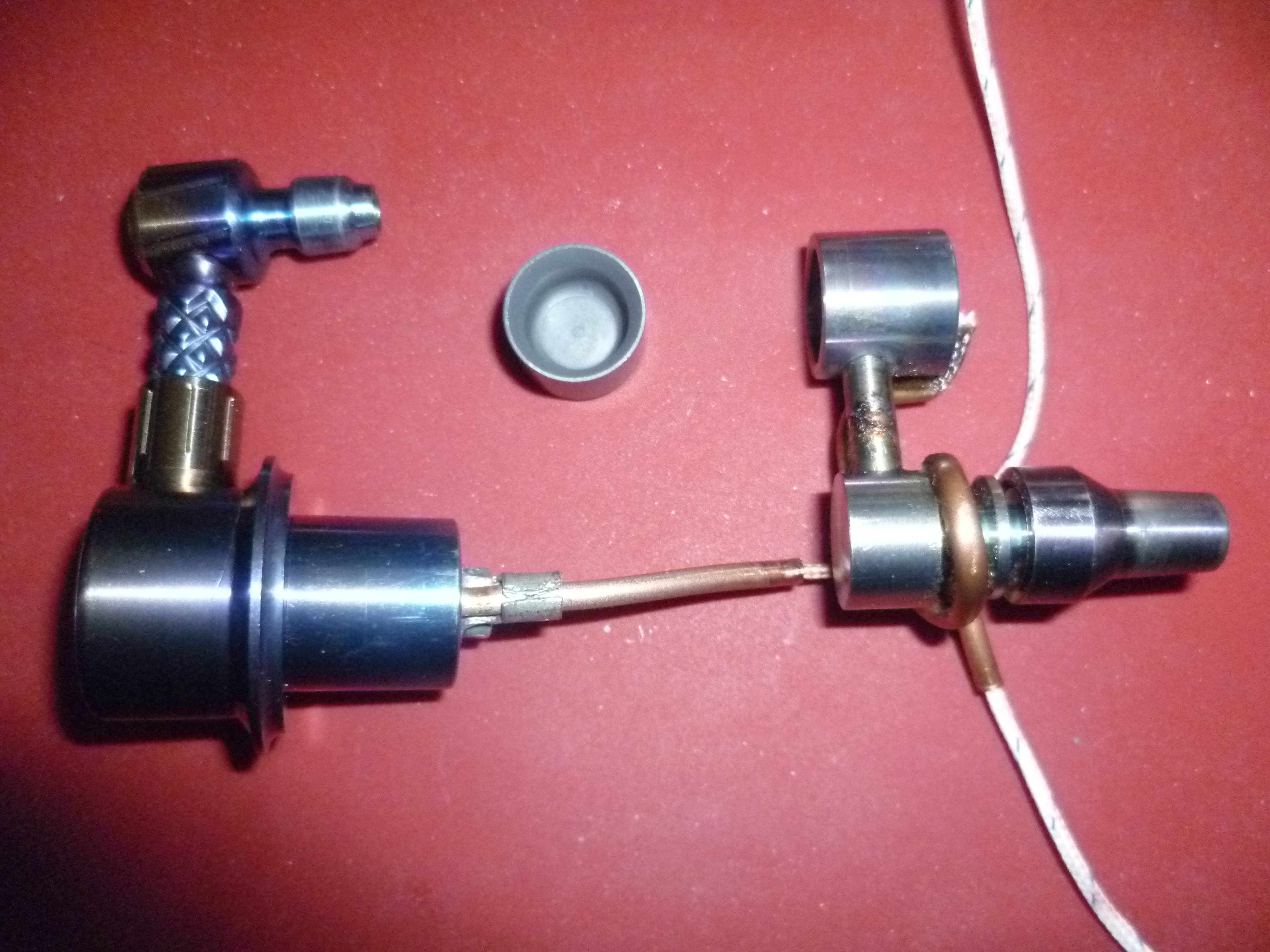
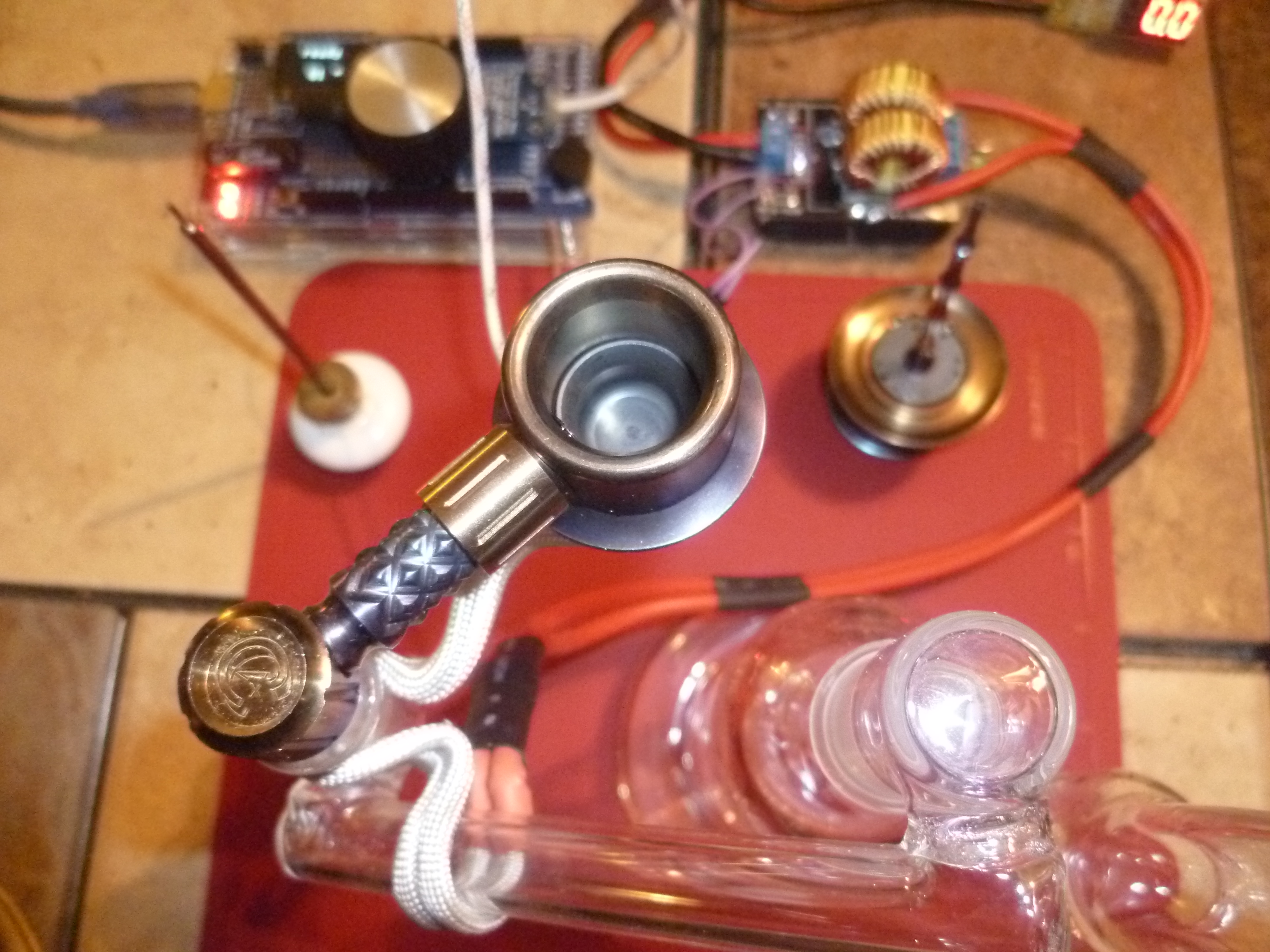
I was intrigued by the banger style nails in particular the Liger but that one isn't in my budget currently so I got this nail from http://www.dhgate.com/product/smoking-dogo-2015-may-new-arrival-universal/238802269.html for $12.85. It fits nicely on my small Silika bubbler with a 14mm to 10mm dropdown. At first I was doing low temp dabs by just using my induction heater modules to heat the nail to a barely visible red and timing the cool down which was a bit tedious and inconsistent. Plus I was heating the nail much more than what was necessary.

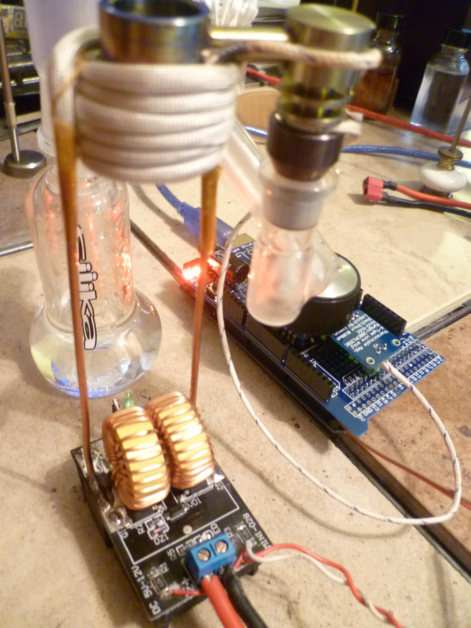
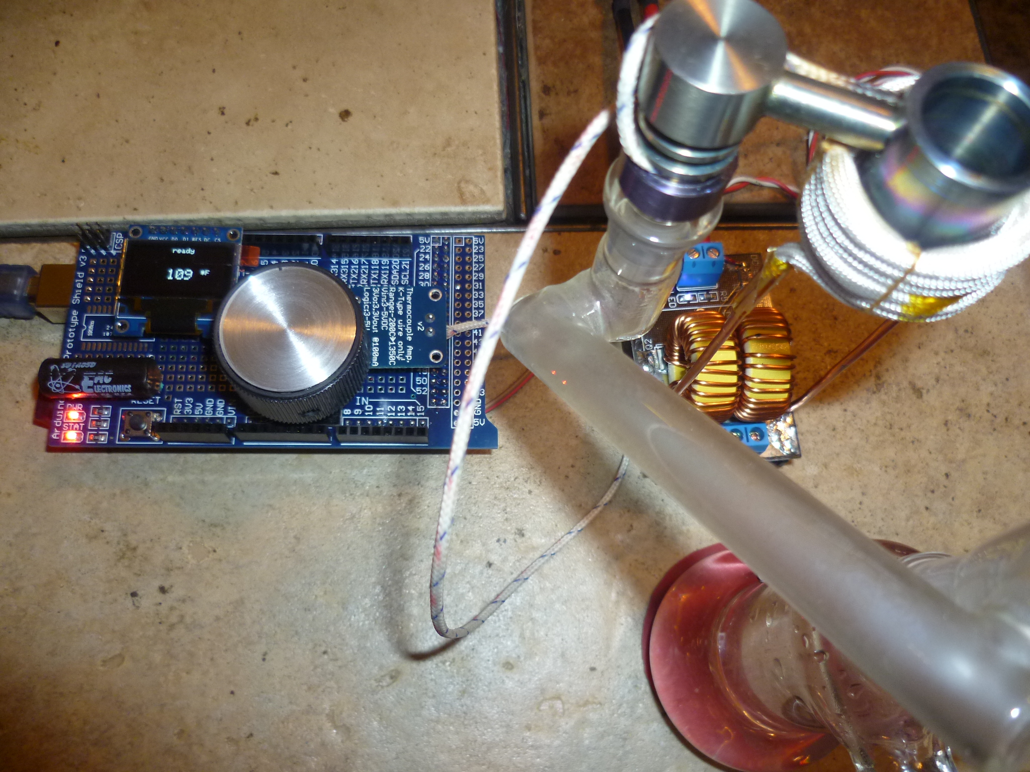
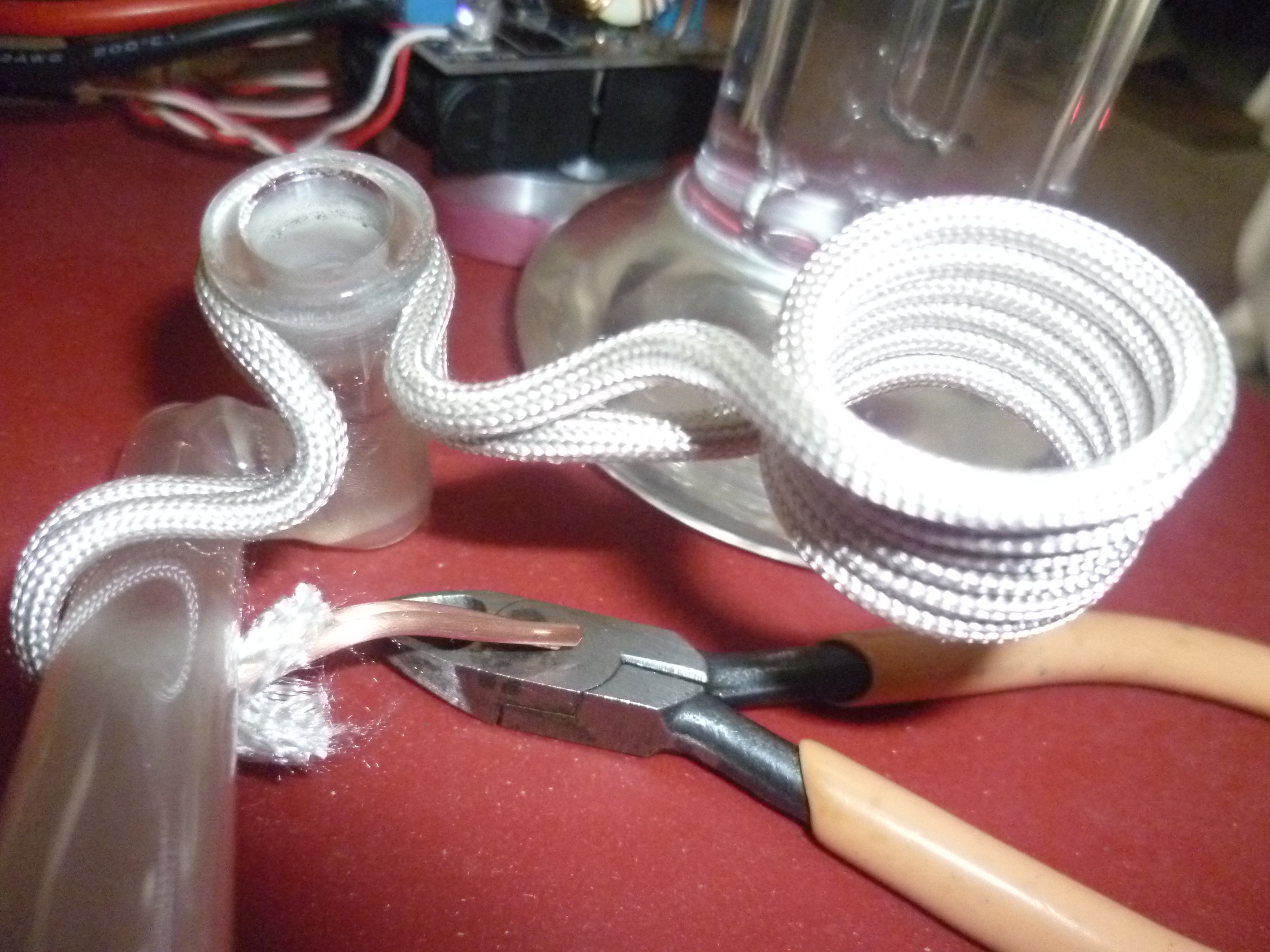
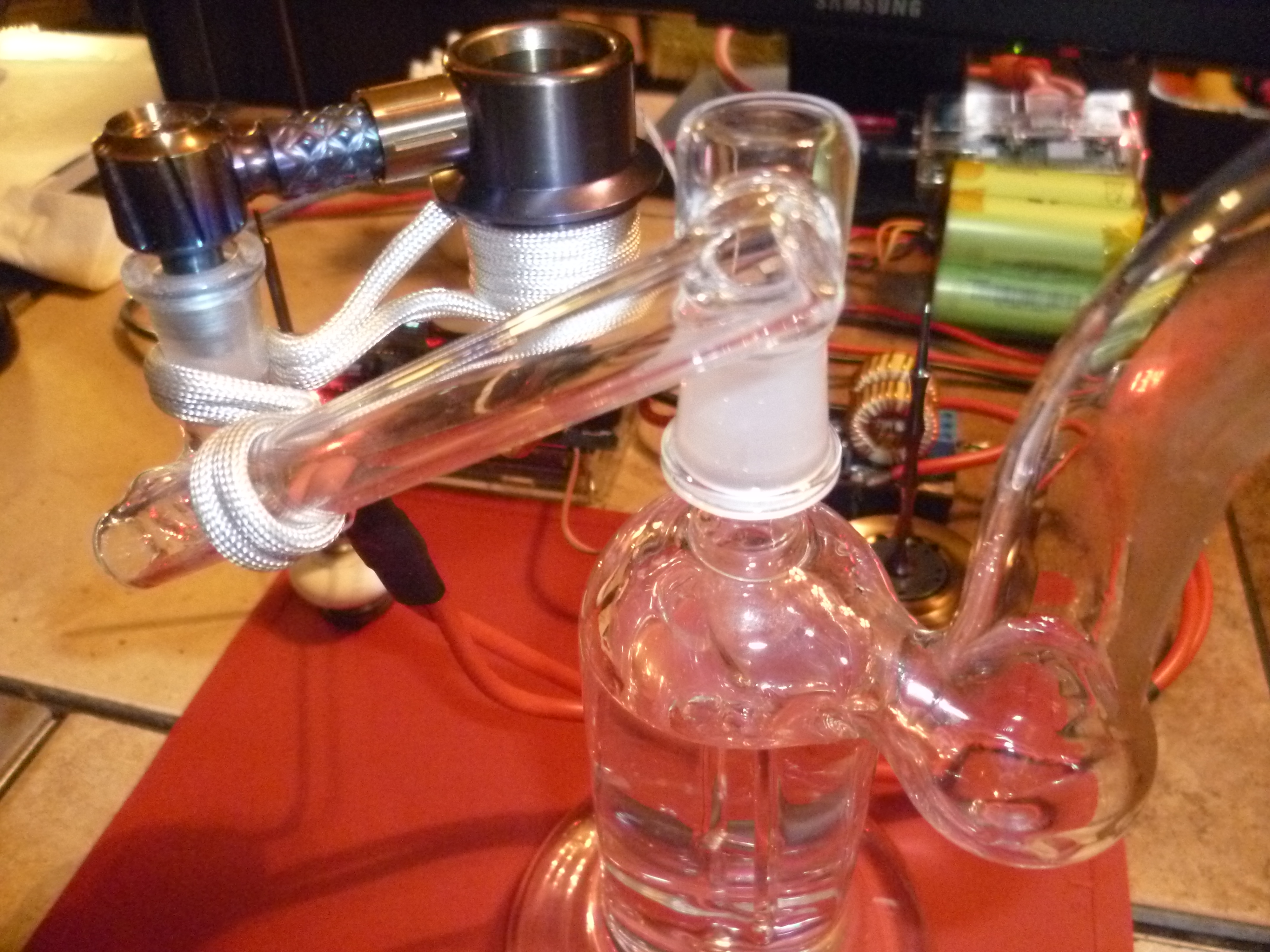
So I had an arduino nano and a max31855 thermocouple amplifier module on hand and decided to use them for a temperature controller to drive the induction heater module. I reversed the mounting of the tank components to the top of the pcb so the module can stand upright using the heatsink as a base. Then I made a new work coil that flips the coil 90 degrees so that the bucket of the e-nail rests inside. This also provides support to the nail and stabilizes the rig which was fairly easy to tip with the dropdown and nail hanging from it. The arduino sketch is pretty basic using some "if" statements. I didn't get to doing any input routines yet so all parameters are hard coded for now.


aRGg1FW


It regulates pretty well for a simple non-PID control usually holding within +/- 5 degrees F.
RpAU12z


It's programmed to run a 100 second heating cycle when the pushbutton is pressed which gives me enough time for 2 draws off of a dab. I have the setpoint at 420 degrees F and I'm enjoying some very flavorful dabs considering I'm dabbing off of Ti. I plan on getting a Liger with the SIC insert ASAP but for experimentation this cheap Chinese banger is great.
It's a bit of a kluge right now but I plan on mounting the components in an aluminum box with the heater and bubbler attached to the top.

Some more pics here: https://imgur.com/a/UtVF6

The arduino sketch is here: https://github.com/hardboiledfrog/e-nail

And a youtube vid here:
 

mrbonsai420

Accessory Maker
Accessory Maker
I would LOVE to see this paired with a Liger but I am not seeing a lot of vapor? Your temps seem very low, could you bump it up and show a thick cloudy dab?. Can you show some dabs and some close ups of the heater and heat exchange system! This is a cool project.
 

hardboiledfrog

tinkerer
I answered this first in the next gen thread but it's worth repeating here.
"The temp of the bottom of the bucket is over a hundred degrees F higher than what the thermocouple reads as it is spot-welded higher up on the side. I actually started with the setpoint at over 600 F and worked down until the taste improved and the remains of the dab didn't smell burnt. The difference in effects wasn't much and I may be wasting a small amount but the taste and no harshness are worth the sacrifice. Now I need to step up to a Liger with a SIC insert." :cool::tup:

There are more pics on the imgur album link above, I didn't upload more there because the last I got blasted for uploading "too many pics of the same thing". What do you want more detail about?

The heater is the same type of induction heater module from before (https://github.com/hardboiledfrog/smt-zvs-driver), but now the arduino nano is turning it on & off quickly to control the heat. A 400w heater module is actually overkill but it does it get the nail up to temp in under 30 seconds. I do plan on designing a smaller wattage heater for this application though. The bucket is heated by just being inside the induction coil, intimate physical contact isn't needed as with conduction heating via resistance heaters. Given the difficulties you have posted about this with the v3 Liger (having to set your heater temps so high) induction heat would be much more effective and efficient for the Ligers and you wouldn't need that bulky shell. I actually prefer the design of the v2 buckets but I do want one of the v3 10mm male main bodies for my small bubbler.

I do small dabs mainly because of difficulty obtaining cannabis in a recently non-medical state, I waste less and I enjoy the ritual of dabbing. The :evil: assholes occupying our state capital legalized medical use effective 9/1/2016 because the voters would have passed a referendum this November but they had absolutely no plans to provide access. This was nothing more than a money-grab for their rich prick cronies to corner the cannabis market as the bastards also kept growing illegal to all but a limited amount of their friends plus there will also be very steep licensing fees to discourage any mom & pop businesses. :mad: :bang:
 

hardboiledfrog

tinkerer
Hey guys just wanted to update my progress. I replaced the heater module with a lower wattage unit from http://www.banggood.com/5V-12V-ZVS-Induction-Heating-Power-Supply-Module-With-Coil-p-1015637.html. This module is good for up to 150W and is much better for this application.

m1rMzu6.jpg

the work coil is 6-1/2 turns (0.850" i.d.) of 12 AWG solid house wire with Alpha Wire PF24010 NA fiberglass high temperature sleeving. this module worked out better for the PID control and conserving battery charge. it was also very inexpensive @ $6 shipped, much less than a typical e-nail heater.

lY2yKGm.jpg

I had to replace the arduino nano with a mega2650 due to running out of memory space after adding the settings menu. It uses a rotary encoder and an OLED display for parameter selections and start / stop control. The temperature can be adjusted in +/- 10 degree increments during a session.

It also has an upTemp function with selectable start temp and ramp-up time, the end temp is whatever the setpoint is. This feature was inspired by the good folks at D-nail: http://www.d-nail.com/info/blog/stabilized-uptemp-procedure-writeup-available/
Thanks @Monsoon for the tip!
XSdbjlE.png


The updated sketch file and parts list is on my github page here: https://github.com/hardboiledfrog/e-nail
More pics here: https://imgur.com/a/UtVF6
 

hardboiledfrog

tinkerer
I would LOVE to see this paired with a Liger

so I got my liger v3 20mm on New Years Eve and got to bang in the New Year properly :D.
this thing is a beast compared to my dhgate Ti banger.

LMXtnp4.jpg


I made a new work coil that is remote from the ZVS module and clips onto my dropdown and helps support the massive liger. this has worked very well and now my rig is much easier to move around than the previous method I used to help support the nail and keep the Silika from tipping over.

Sb5GQJk.jpg


I also picked up an fc710 because the liger was kind of big for my tiny Silika bubbler.

8ot8gJn.jpg

5SA7oel.jpg


the liger with the SiC dish is a huge improvement over my previous Ti banger in both taste and function and the fc710 has comparable flavor to the Silika with a much smoother hit. the only downside is the draw is difficult to feather but the smoothness and stability of the larger piece makes this a non-issue for me.

more pics here: http://imgur.com/a/lFThz
 

mrbonsai420

Accessory Maker
Accessory Maker
so I got my liger v3 20mm on New Years Eve and got to bang in the New Year properly :D.
this thing is a beast compared to my dhgate Ti banger.

LMXtnp4.jpg


I made a new work coil that is remote from the ZVS module and clips onto my dropdown and helps support the massive liger. this has worked very well and now my rig is much easier to move around than the previous method I used to help support the nail and keep the Silika from tipping over.

Sb5GQJk.jpg


I also picked up an fc710 because the liger was kind of big for my tiny Silika bubbler.

8ot8gJn.jpg

5SA7oel.jpg


the liger with the SiC dish is a huge improvement over my previous Ti banger in both taste and function and the fc710 has comparable flavor to the Silika with a much smoother hit. the only downside is the draw is difficult to feather but the smoothness and stability of the larger piece makes this a non-issue for me.

more pics here: http://imgur.com/a/lFThz


YES! Lets see a milky dab video with this awesome induction Liger!!!!:rockon:
This is a cool project @CCA710
 

jwatttt

Well-Known Member
thanks! I'll try to get a new video up soon but I must warn you, my camera isn't so great and neither is my photography skillset. :rolleyes:
Any possibility of adding clip on thermocouples to add temp accuracy by averaging between them? I really like your design too! how large is the battery footprint?
 

hardboiledfrog

tinkerer
thanks @jwatttt . sure, you could add another thermocouple, that's what's nice about using an arduino for the controller.
the battery pack I'm currently using is about 2" x 2" x 3" but is only 2.3 Ahr which is too small for the Liger. I only get 4 dab sessions now per charge, I need to replace that with about a 10 or 12 Ahr battery pack.
 
hardboiledfrog,

Pipes

Addicted DIY Enthusiast
Accessory Maker
Excellent stuff!! Well done. :D:science:

This information is right down the same vein as the "VapCap Induction Heater for Desktop and in Car Use" thread.
The only part you might want to change is the relay module which the links took me to. A better suited part would be a MOS PWM Driver which will cut down on the chattering you must be hearing from the relay. IMO, a more suitable solution.
Love this stuff...:love:
 
Last edited by a moderator:

hardboiledfrog

tinkerer
Excellent stuff!! Well done. :D:science:

This information is right down the same vein as the "VapCap Induction Heater for Desktop and in Car Use" thread.
The only part you might want to change is the relay module which the links took me to. A better suited part would be a MOS PWM Driver which will cut down on the chattering you must be hearing from the relay. IMO, a more suitable solution.
Love this stuff...:love:

hi @Pipes , thanks for the kind words. I briefly checked out your vapcap thread, I need to go back and read the whole thread, awesome! I see your using the same heater module. that's a great application, I love this stuff too!
also thanks for the mosfet switch link, it's exactly what I've been looking for and I agree that it would be much better than the relay module.
 

JCat

Well-Known Member
Accessory Maker
hi @Pipes , thanks for the kind words. I briefly checked out your vapcap thread, I need to go back and read the whole thread, awesome! I see your using the same heater module. that's a great application, I love this stuff too!
also thanks for the mosfet switch link, it's exactly what I've been looking for and I agree that it would be much better than the relay module.
Hi @Pipes and @hardboiledfrog,

I'm not quite sure I understand how to connect the MOSFET to switch the ZVS driver, or why I should do this specifically over using an SSR. I see that there are some wires soldered to the R1 and R3 resistors on the board, and I assume that is connected back to the MOSFET (which I don't see in any of the pictures) to control the switching?

If I'm understanding correctly, the MOSFET just takes a 0-20khz PWM signal to switch it ... but what are the wires soldered to R1 and R3 and why don't I see this MOSFET anywhere? ... or do these pics not have that MOSFET and it's being controlled differently?

I have the following PWM module (https://www.robotshop.com/ca/en/cytron-13a-5-30v-single-dc-motor-controller.html), can this be used? Should this not just go between my 12V 10A power supply and the ZVS driver module? And then I can control the duty cycle using the PWM frequency that I send to it?

Thanks!
 
JCat,
  • Like
Reactions: Pipes

rz

Well-Known Member
Hey @JCat That Cytron module you have is a LOT more than a PWM module! :) It is more than capable of driving your ZVS module (in the CORRECT configuration), but it is designed to drive motors, and is capable of 'flipping' the output around to make a motor go backwards - something you need to AVOID while using this module for driving a ZVS.

I'd start with hooking the cytron board up to Power + and - accordingly, then your ZVS + input to the cytron A output, and the B output to your ZVS ground/negative.

Then take a look at the truth table and notice the top two lines. If you tie DIR input to LOW (GND), then PIN 2 PWN input will control the A output with the correct polarity. The bottom row of that truth circuit would result in backwards connected ZVS and most certainly some damage would result and this should be avoided.

Another thing to note is "** Actual output frequency is same as input frequency." This implies that pin 2 directly relates to output A state which is good.

This connection would be similar to @Pipes induction heaters and should successfully switch your ZVS. The Cytron module should be protected enough to deal with this switching as it is designed for motors which are more taxing on the switching device.

As for PWM frequency, I've found that ~10Hz is plenty. ZVS oscillates at about 25Khz, so modulating at 1Khz would fit only 25 oscillations in per cycle and give you very little resolution and is rather unnecessary. 20Khz would probably wreak havoc somehow. I would try stay below 100Hz though. If your microcontroller doesnt support such low PWM frequencies, you may need to find a library or manually bitbang the output (use your own timer and decide to be on or off).


The wires you see going into @hardboiledfrog's ZVS are connected to the gate resistors of the ZVS. You could also PWM those to control the circuit. The advantage is that you can keep your ZVS hardwired to your power supply, and use a much smaller mosfet to drive the MOSFETS. Make sure your ZVS is supplied with at least ~5V (depending on the mosfets you have) and the gate resistors should be driven with at least 8v. 12v on both should be much better. If you are interfacing with a microcontroller, you would need two transistors to pull this off as it is high side switching driven by logic levels. If I've lost you already, keep this for another day after further discussion..
(more info on this here: VapCap Induction Heater for Desktop and in Car Use)

good luck and keep us updated :)
 

JCat

Well-Known Member
Accessory Maker
Hey @JCat That Cytron module you have is a LOT more than a PWM module! :) It is more than capable of driving your ZVS module (in the CORRECT configuration), but it is designed to drive motors, and is capable of 'flipping' the output around to make a motor go backwards - something you need to AVOID while using this module for driving a ZVS.

I'd start with hooking the cytron board up to Power + and - accordingly, then your ZVS + input to the cytron A output, and the B output to your ZVS ground/negative.

Then take a look at the truth table and notice the top two lines. If you tie DIR input to LOW (GND), then PIN 2 PWN input will control the A output with the correct polarity. The bottom row of that truth circuit would result in backwards connected ZVS and most certainly some damage would result and this should be avoided.

Another thing to note is "** Actual output frequency is same as input frequency." This implies that pin 2 directly relates to output A state which is good.

This connection would be similar to @Pipes induction heaters and should successfully switch your ZVS. The Cytron module should be protected enough to deal with this switching as it is designed for motors which are more taxing on the switching device.

As for PWM frequency, I've found that ~10Hz is plenty. ZVS oscillates at about 25Khz, so modulating at 1Khz would fit only 25 oscillations in per cycle and give you very little resolution and is rather unnecessary. 20Khz would probably wreak havoc somehow. I would try stay below 100Hz though. If your microcontroller doesnt support such low PWM frequencies, you may need to find a library or manually bitbang the output (use your own timer and decide to be on or off).


The wires you see going into @hardboiledfrog's ZVS are connected to the gate resistors of the ZVS. You could also PWM those to control the circuit. The advantage is that you can keep your ZVS hardwired to your power supply, and use a much smaller mosfet to drive the MOSFETS. Make sure your ZVS is supplied with at least ~5V (depending on the mosfets you have) and the gate resistors should be driven with at least 8v. 12v on both should be much better. If you are interfacing with a microcontroller, you would need two transistors to pull this off as it is high side switching driven by logic levels. If I've lost you already, keep this for another day after further discussion..
(more info on this here: VapCap Induction Heater for Desktop and in Car Use)

good luck and keep us updated :)
Perfect :) This was very helpful and just gave me confidence that my understanding of things was correct. (it was, that the pictures weren't using the MOSFET but @hardboiledfrog was controlling the ZVS directly through the gate resistors) that's cool and may go down that route eventually but I'm going to proceed with the motor PWM control I've got for my prototyping ... it will just be easier for me :) ... I very much followed what you were saying, and thanks for the tip on tying the DIR input to the GND to prevent going in the wrong direction :) (that's what I thought that it was fine but too much in that it was bi-directional)

Edit: Hey @rz (and others), maybe you can answer this question for me too, as I seem to be getting conflicting information from different people I've asked and online when I ask Google :)

"Can you heat Silicon Carbide directly through induction?" ... just curious ... :lol: ... might be pretty cool if you can!
 
Last edited:
JCat,
  • Like
Reactions: rz
Top Bottom