Short Portside Update.
Ironing out a couple details but everything is on order. Enclosures have shipped.
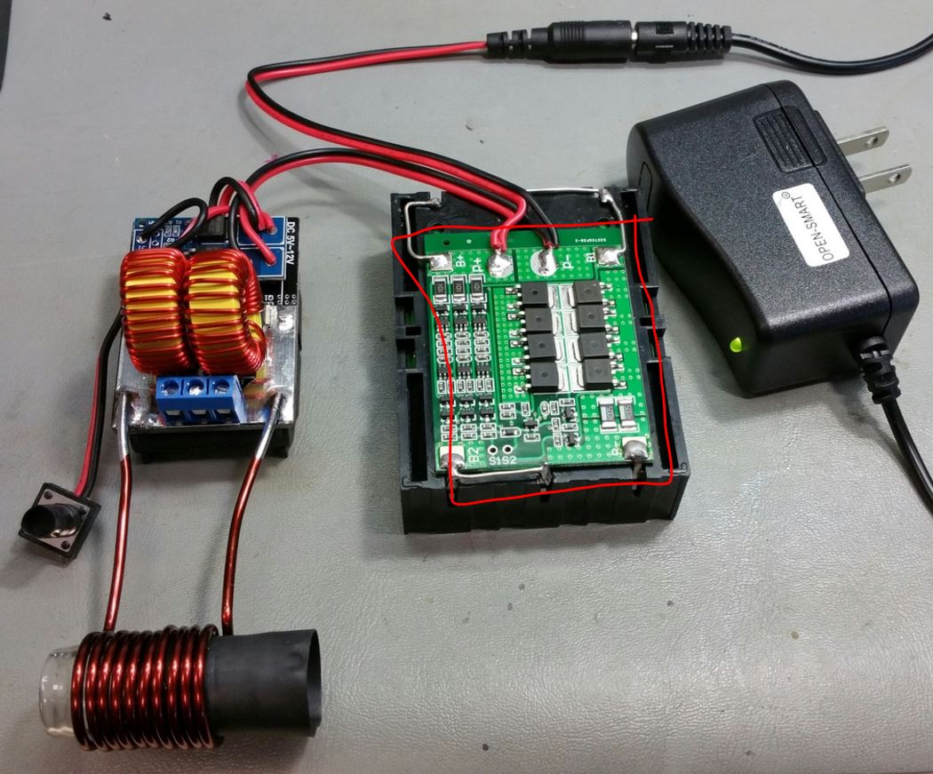
I decided a master power switch was needed on the Portside as a safety measure. The reason is for a scenario where the tactile switch gets stuck in an "on" state. Not a huge chance of this but if it did, the device would run until batteries died or something fails. Either way, would be lots of smoke.
Not needed for other models as can either pull plug or batteries out. Folks making their own boxes should keep this in mind. Switches are on order as well.
Also, want an illuminated light to show when the heater is on. Have some 4mm clear fiber cord on order as hoping to guide some of the existing LED light up to the glass tube. Or if that fails, just run an LED up to the rim of glass.
So have a couple weeks to continue testing....
Ironing out a couple details but everything is on order. Enclosures have shipped.
I decided a master power switch was needed on the Portside as a safety measure. The reason is for a scenario where the tactile switch gets stuck in an "on" state. Not a huge chance of this but if it did, the device would run until batteries died or something fails. Either way, would be lots of smoke.
Not needed for other models as can either pull plug or batteries out. Folks making their own boxes should keep this in mind. Switches are on order as well.
Also, want an illuminated light to show when the heater is on. Have some 4mm clear fiber cord on order as hoping to guide some of the existing LED light up to the glass tube. Or if that fails, just run an LED up to the rim of glass.
So have a couple weeks to continue testing....
Last edited:

")


 ) and turn off the heat.
 )
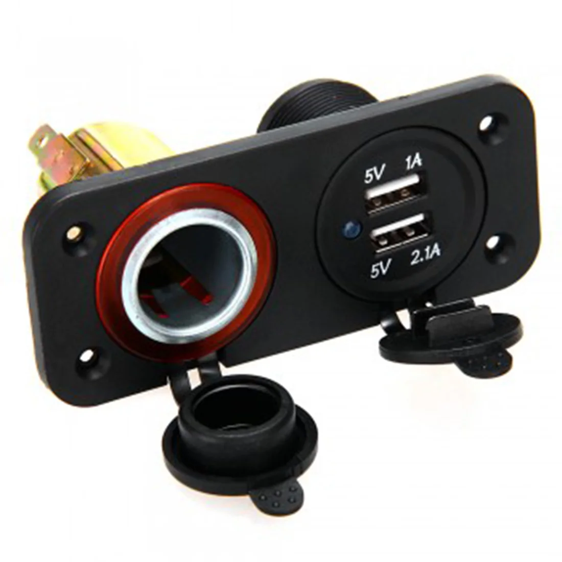
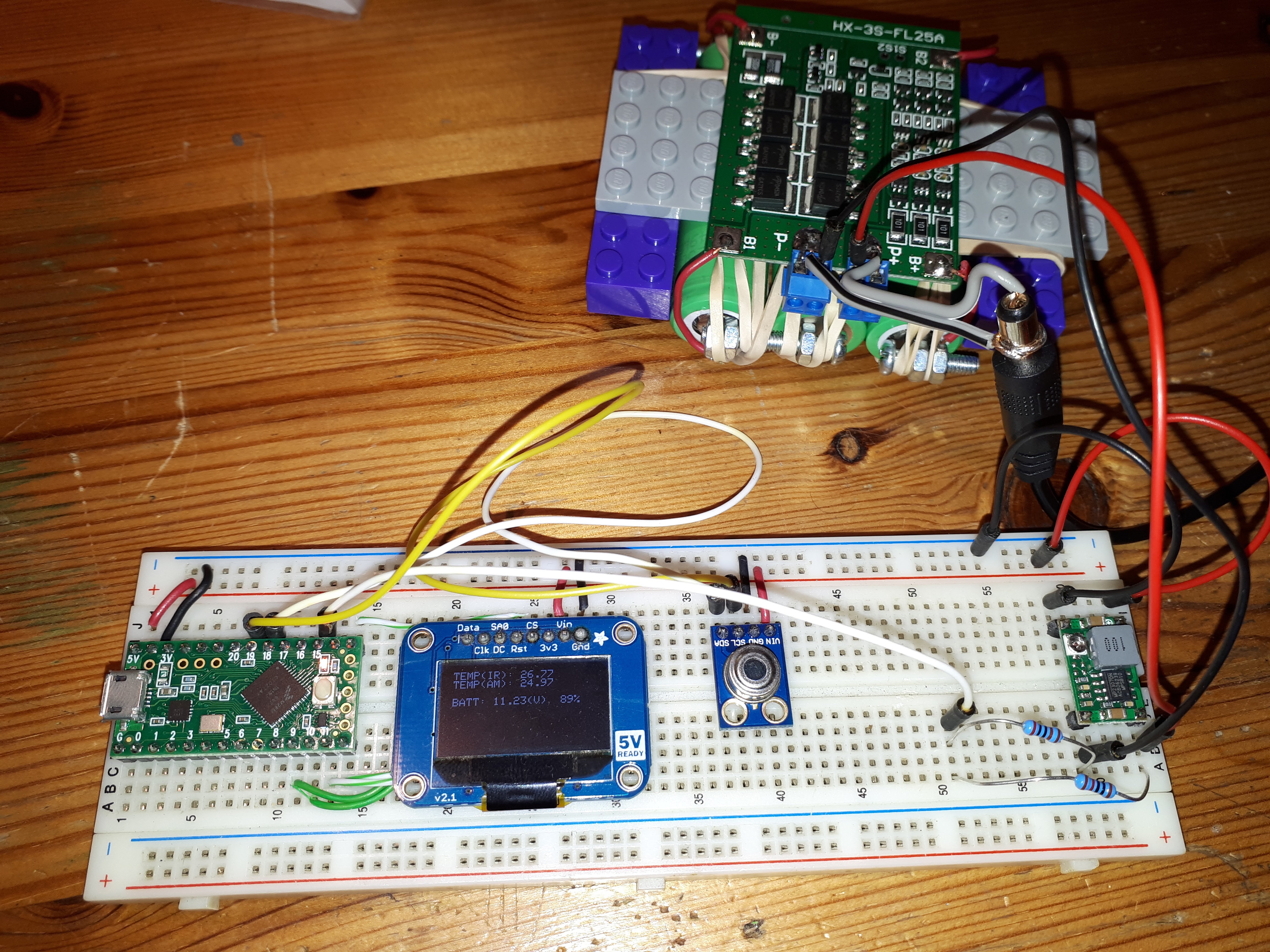
) but now, here's a question.. how much extra would you guys pay to put a microcontroller and OLED display on the portside 2.0? The one with the USB charger on it..
 Officer, It's just a 12v socket splitter