
GreenHopper
20 going on 60
First off, thanks to you all for your help and advice. Is it me, or are vapcap users generally some of the friendliest, most open vaporists around?
Next, a huge respect to @Pipes for your amazing work and genius. So many of you vaporizer and accesory manufacturers also come across as such decent and caring people who do what you do first for love and second for money.
I am always humbled when I see someone doing such a good task and achieveing so much while busy life goes on around.
I have been very ill for 12 years due to Lyme Disease and multiple other infections and problems. My condition is so debikitating, and managing my allergy symptoms is so demanding, I am unable to achieve anything except washing, getting meals, and managing my symptoms round the clock.
I barely make it put of the house or get anything done at home. So it always blows me away when I see the work you guys do. I have the utmost respect.
Moving on, I have really enjoyed my omnivap the last 2 days. I have missed it. However it is already causing serious issues with my hands and wrists. If I am going to want to use my Omnivap a lot, I will certainly want one of these chargers.
I just need to decide which model. @GreenHopper 's links have been very helpful. I have read throuh a lot of the thread. However my brain function and memory is severely compromised due to health issues. So I have struggled to get a totally clear view of all the ins and outs, pros and cons etc.
At first I thought the jarhead will be sufficient. Partly because it is a bit cheaper. And partly because I tolerate the vapcap vapor much better through water.
And It would be nice to be able to use in a car as well.
Im not clear which of the models can work off of a car yet (I know the portside will).
Ideally I would like to use a wall connection at home, and batteries away. The portside sounds like it may be sufficient for all needs though, without longevity of the batteries being an issue (both short term charge holding, and long term for recharging purposes), although I do wonder how often batteries will need repacing, so as to factor costs.
I'm also trying to get clear on the additional costs for each model. For the portside we just need to get the batteries right? Except Pipes said also the charger will need an EU adapter, unless we find our own charger for a cost reduction.
As Pipes said he still has some EU power supplies for the jarhead, Im assuming the power supply is included in the package, so no additional cost for the jarhead?
Im not yet clear on the skeletor yet, if it can work off a car cigiarette lighter etc.
So if Ive got it right, the jarhead total cost with slow boat shipping is $85? Nothing else required?
The portside will be $115 slow boat shipping, plus the battery cost as well?
If correct, I think the jarhead is the only option really due to lower costs. Im just thinking aloud really, no need for anyone to address all of these points unless I have something mistaken.
My thumbs and wrists are buggered already from 6 loads the last 2 days. Im going to a chiropractor now and she will adjust everything, there is no way I can continue to use the vapcap and torch.
That's all. I will keep reading to get a better idea of the details. Big love going ou to the whole community here at fc, and a special thanks to the vapcappers for your warmth and recepriveness.
Looks like you have a good understanding of whats what.
I think if cost is a factor then the JarHead is your best option.
If you are willing to spend the bit extra then the PortSide offers the portability option.
The Skeletor/Kit options are more for modders who want to create their own cases, install in altoid cases, build the unit from scratch, etc... If you have issues with grip strength then you'll probably just want an out of the box solution in which case the JarHead or PortSide are your best bets.
Turns out Power Adapters are included in the package for each respective unit and should be capable of 100-240v use. The battery units will use a power supply with intelligence to control the charge rate where as the direct draw units like the JarHead will use a more basic but higher wattage Power Supply.
This would just leave a requirement for a basic plug adapter for converting the pins to you local standard assuming your local standard isn't the USA dual flat pin standard.
Like you I have a great deal of respect for @Pipes, @rz, @Andreaerdna and @hardboiledfrog for their knowledge and enthusiasm. I'm very impressed by their open and friendly nature and willingness to share the journey with all of us.
The VapCap crowd are also extremely friendly, I like to believe that this is partly because @VapCap has shown an incredible community oriented style to their Dynavap product delivery which has gone on to inspire others.
Lastly, I'm getting the PortSide as I think it is going to be a real improvement for my convenience but your story makes me realise just how great this project and device is for helping those with dexterity and grip strength limitations when working with the VapCap.

")


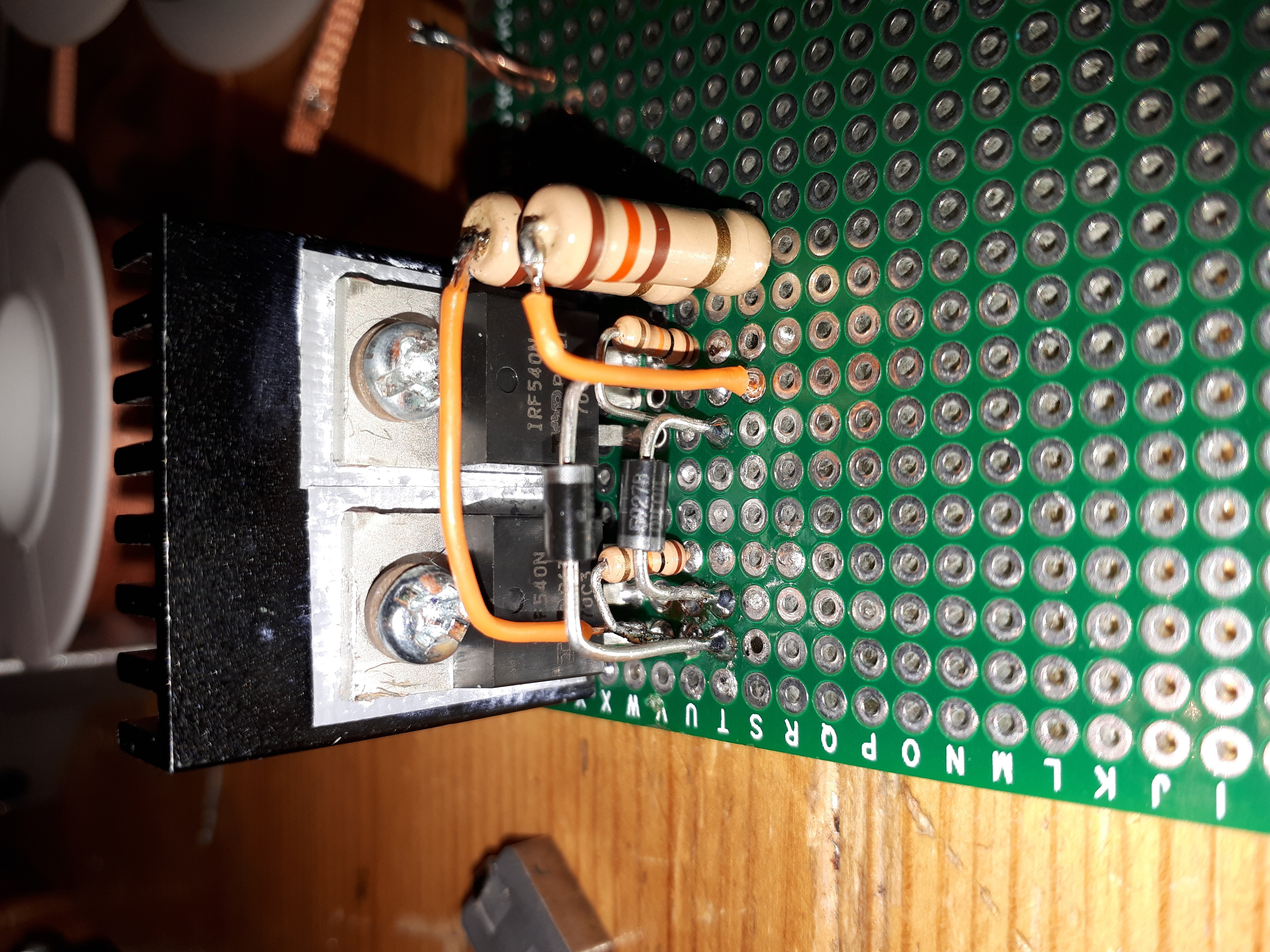
 Only after switching out transistors did I notice the resistor issue. Fixed and fixed. Everything was running coooool to the touch, and HOT on the vapcap!

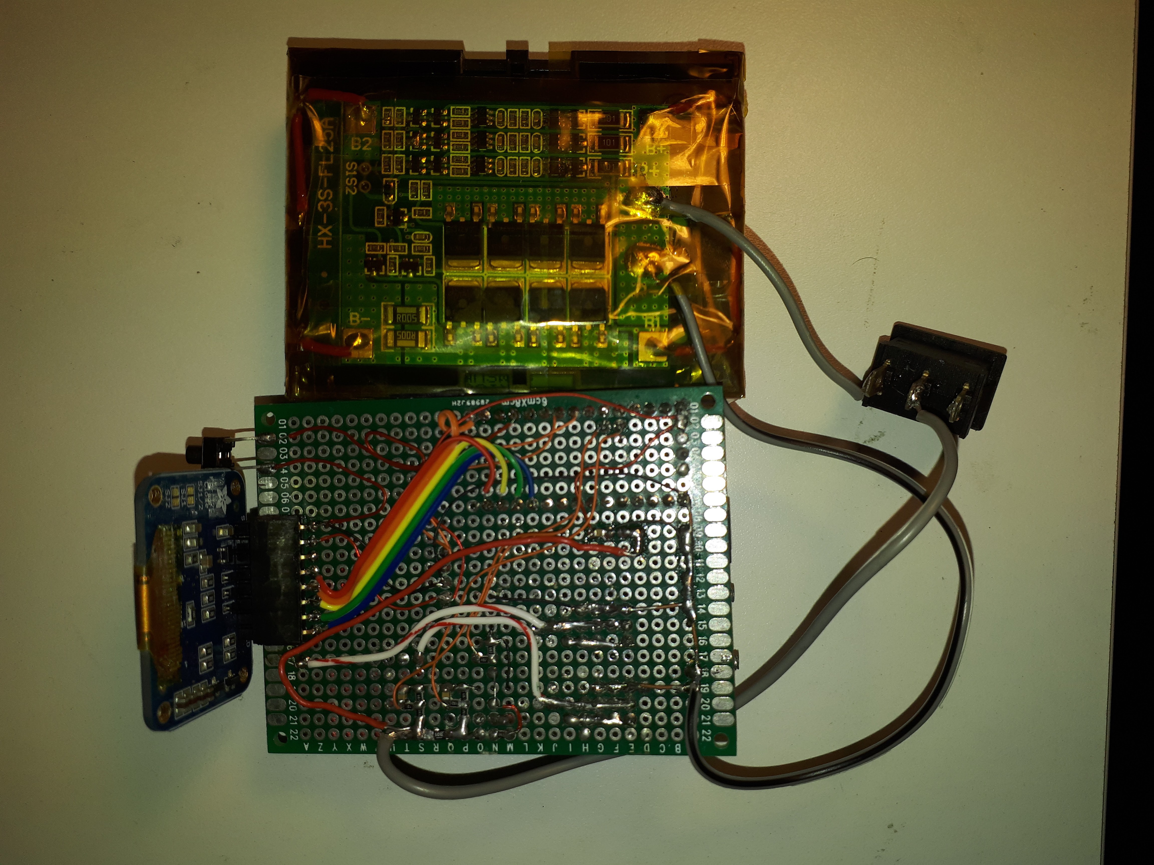


") ), but maybe this is the core of a whole new vape?
), but maybe this is the core of a whole new vape? 


 ' innovations being thrown around here
  !
!

