VapCap Induction Heater for Desktop and in Car Use

GreenHopper

20 going on 60
First off, thanks to you all for your help and advice. Is it me, or are vapcap users generally some of the friendliest, most open vaporists around?

Next, a huge respect to @Pipes for your amazing work and genius. So many of you vaporizer and accesory manufacturers also come across as such decent and caring people who do what you do first for love and second for money.

I am always humbled when I see someone doing such a good task and achieveing so much while busy life goes on around.
I have been very ill for 12 years due to Lyme Disease and multiple other infections and problems. My condition is so debikitating, and managing my allergy symptoms is so demanding, I am unable to achieve anything except washing, getting meals, and managing my symptoms round the clock.

I barely make it put of the house or get anything done at home. So it always blows me away when I see the work you guys do. I have the utmost respect.

Moving on, I have really enjoyed my omnivap the last 2 days. I have missed it. However it is already causing serious issues with my hands and wrists. If I am going to want to use my Omnivap a lot, I will certainly want one of these chargers.

I just need to decide which model. @GreenHopper 's links have been very helpful. I have read throuh a lot of the thread. However my brain function and memory is severely compromised due to health issues. So I have struggled to get a totally clear view of all the ins and outs, pros and cons etc.

At first I thought the jarhead will be sufficient. Partly because it is a bit cheaper. And partly because I tolerate the vapcap vapor much better through water.

And It would be nice to be able to use in a car as well.
Im not clear which of the models can work off of a car yet (I know the portside will).

Ideally I would like to use a wall connection at home, and batteries away. The portside sounds like it may be sufficient for all needs though, without longevity of the batteries being an issue (both short term charge holding, and long term for recharging purposes), although I do wonder how often batteries will need repacing, so as to factor costs.

I'm also trying to get clear on the additional costs for each model. For the portside we just need to get the batteries right? Except Pipes said also the charger will need an EU adapter, unless we find our own charger for a cost reduction.

As Pipes said he still has some EU power supplies for the jarhead, Im assuming the power supply is included in the package, so no additional cost for the jarhead?

Im not yet clear on the skeletor yet, if it can work off a car cigiarette lighter etc.

So if Ive got it right, the jarhead total cost with slow boat shipping is $85? Nothing else required?

The portside will be $115 slow boat shipping, plus the battery cost as well?

If correct, I think the jarhead is the only option really due to lower costs. Im just thinking aloud really, no need for anyone to address all of these points unless I have something mistaken.

My thumbs and wrists are buggered already from 6 loads the last 2 days. Im going to a chiropractor now and she will adjust everything, there is no way I can continue to use the vapcap and torch.

That's all. I will keep reading to get a better idea of the details. Big love going ou to the whole community here at fc, and a special thanks to the vapcappers for your warmth and recepriveness.:love:

Looks like you have a good understanding of whats what.

I think if cost is a factor then the JarHead is your best option.

If you are willing to spend the bit extra then the PortSide offers the portability option.

The Skeletor/Kit options are more for modders who want to create their own cases, install in altoid cases, build the unit from scratch, etc... If you have issues with grip strength then you'll probably just want an out of the box solution in which case the JarHead or PortSide are your best bets.

Turns out Power Adapters are included in the package for each respective unit and should be capable of 100-240v use. The battery units will use a power supply with intelligence to control the charge rate where as the direct draw units like the JarHead will use a more basic but higher wattage Power Supply.

This would just leave a requirement for a basic plug adapter for converting the pins to you local standard assuming your local standard isn't the USA dual flat pin standard.

Like you I have a great deal of respect for @Pipes, @rz, @Andreaerdna and @hardboiledfrog for their knowledge and enthusiasm. I'm very impressed by their open and friendly nature and willingness to share the journey with all of us.

The VapCap crowd are also extremely friendly, I like to believe that this is partly because @VapCap has shown an incredible community oriented style to their Dynavap product delivery which has gone on to inspire others.

Lastly, I'm getting the PortSide as I think it is going to be a real improvement for my convenience but your story makes me realise just how great this project and device is for helping those with dexterity and grip strength limitations when working with the VapCap. :tup:
 

Alexis

Well-Known Member
Looks like you have a good understanding of whats what.

I think if cost is a factor then the JarHead is your best option.

If you are willing to spend the bit extra then the PortSide offers the portability option.

The Skeletor/Kit options are more for modders who want to create their own cases, install in altoid cases, build the unit from scratch, etc... If you have issues with grip strength then you'll probably just want an out of the box solution in which case the JarHead or PortSide are your best bets.

Turns out Power Adapters are included in the package for each respective unit and should be capable of 100-240v use. The battery units will use a power supply with intelligence to control the charge rate where as the direct draw units like the JarHead will use a more basic but higher wattage Power Supply.

This would just leave a requirement for a basic plug adapter for converting the pins to you local standard assuming your local standard isn't the USA dual flat pin standard.

Like you I have a great deal of respect for @Pipes, @rz, @Andreaerdna and @hardboiledfrog for their knowledge and enthusiasm. I'm very impressed by their open and friendly nature and willingness to share the journey with all of us.

The VapCap crowd are also extremely friendly, I like to believe that this is partly because @VapCap has shown an incredible community oriented style to their Dynavap product delivery which has gone on to inspire others.

Lastly, I'm getting the PortSide as I think it is going to be a real improvement for my convenience but your story makes me realise just how great this project and device is for helping those with dexterity and grip strength limitations when working with the VapCap. :tup:
Thanks a ton again for your help. In that case I think I have it all clarified. And yes, as much as having the portable unit would be nice I cant really justify the cost at the moment, health maintenance has to take financial priority.

Therefore I think, count me in for one jarhead! So do I need to pm Pipes or something?
I am actually commencing another 30 day vapor break to take homeopathy to treat infections.

I was supposed to start the vapor break 2 days ago when I started the homeopathy, but my head was not in the right place so out came the Omnivap. I had forgotten just how strong and complete the buzz is compared to other vapes. I love it and I want it back in my life for good, so I hope to instigate a jarhead travelling my way to look forward to!
 

GreenHopper

20 going on 60
Thanks a ton again for your help. In that case I think I have it all clarified. And yes, as much as having the portable unit would be nice I cant really justify the cost at the moment, health maintenance has to take financial priority.

Therefore I think, count me in for one jarhead! So do I need to pm Pipes or something?
I am actually commencing another 30 day vapor break to take homeopathy to treat infections.

I was supposed to start the vapor break 2 days ago when I started the homeopathy, but my head was not in the right place so out came the Omnivap. I had forgotten just how strong and complete the buzz is compared to other vapes. I love it and I want it back in my life for good, so I hope to instigate a jarhead travelling my way to look forward to!

I think thats a good choice.

Looks like @Pipes has 'Liked' your post so I guess he is aware of your interest but I'd PM him so that he has a record and can respond with transaction details.

Hope this all works out for you bud :)
 

grokit

well-worn member
I can relate :nod:

I can definitely appreciate the utility of the portside system considering how portable the vapcap/omnis are. But I really wanted to try this tech, and my vas funds are also limited/being re-directed atm.

Obviously the jarhead can be transportable tho, with the right cup-holder and an inverter :tup:
 

Alexis

Well-Known Member
People, Pipes has already packed my jarhead ready for shipping can you believe (like a couple hours ago now) and sent me photo of the package just to make me salivate until the slow boat arrives!:drool:
He just wanted to get the "boat" moving right away. What a service and what a guy! You can see clearly how he really cares about making people happy, and this is his motivation.

It would have taken me about 3 weeks to do that, let alone make all the devices in the first place while keeping up with the pace of life.
I already feel so good about this purchase due to the feelings I have about his work, services and warm wishes.

And thanks @Stu for the timely video. You are a 1st class respected vaporist, so when you endorse something with your seal of approval we all know it is good!
 

Pipes

Addicted DIY Enthusiast
Accessory Maker
Nice vid Stu! :cool:
Thanks for the kind words @Alexis, it is a fulfilling hobby and helping folks out is always a warming benefit. :luv:

I've being working some more on the FAQ sheet you guys requested. It is in my signature by clicking the VC pic but here is a posted copy.

Let me know if any other information should be added. :)

-------------------------------------------------------------------------------------------------------------------------

VC Induction Heater FAQ

The Induction heater is a new concept to replace the use of a flame type lighter to heat the VapCap Vaporizer line up.

I currently make two models which are complete with no work needed by the end user except supply batteries for the Portside version. They are the called Jarhead and Portside.

The Jarhead is an Induction heater mounted inside a glass jar with the access port in the lid. This unit requires an external 12 volt high current power supply which come with the package. It uses a 5.5X2.1mm standard DC connectors which detach at side of the Jarhead.
To activate the heater, you simply press the VC strait into the hole until you feel/hear the tactile switch engage and LED light goes on. Once the VC clicks, wait another 3-4 count before removing to inhale.

The Portside is the portable unit which has a built in power pack for using detached from any wiring. The unit is made into an aluminum enclosure which has the VC access hole and DC charger input the same as the Jarhead, but also has a main power switch which is for safety in the case you need to kill power to the induction driver. The batteries can be charged regardless of the switch position. Unlike the Jarhead, this unit requires a special battery charger instead of a 12 volt supply. The supplied charger is a 12.6 volt 1 amp smart charger, which stops the charge cycle once battery is fully charged. Only use this type charger while batteries are inserted.
Batteries are the responsibility of the buyer. Flat top 18650 cells with at least a 20 amp rating are recommended. Pending mAhs, charging takes around 2 hours from exhausted to full.
Note to advanced users: The Portside can be run like a Jarhead if batteries are removed. Meaning a high output 12 volt supply can be used, if batteries are removed ONLY!
Do not get charger and supply confused. Can have very bad results.

DIY Skeletor is the same working functions as the Portside but has no enclosure.
The components are all pre-assembled and usable as it is but is naked. Thus, the name, Skeletor. It has the smallest possible configuration and enclosure ideas include:
-building a box around it.
-finding a suitable sized container and simply drop in.
-get fancy and artsy with some expanding foam and make a conversation piece. Google expanding foam ideas. (experimental)

CUSTOM KITS are also possible. Let me know how you plan to use and mount and I’ll accommodate to make your efforts effortless.

FAQs

Q: Everything is plugged in but no heat or lights.
A: Make sure you are pressing the tachil switch in the coil until you feel/hear it click.
Check that batteries are inserted correctly. Pack is configured for series operation.
Ensure batteries are all equally charged and are rated for at least 20 amps continuous.
If using a power supply unit, ensure the light is on in the power supply and plugged in.

Q: Can I use a 12 volt power supply to charge the unit?
A: Answer is absolutely NOT. These are 4.2 volt cells and in series you need 12.6v dead on. And it's a charger, NOT a power supply. It has built in intelligence that slow downs and stops charging at the full charge mark. It has an indicator LED on it that goes from red while charging to green when done.
Using a supply will pump 12 volts at it's max output into the cells with no intelligence as to when they are full. Which they'll never reach because of low voltage. The big danger is say one plugs this into a car plug with almost unlimited amps. It will try and charge at super high amps, this would not be a pretty sight. The BMS offers no protection for charge rate a will allow up to 35 amps to pass.

BIG WARNING: Only used supplied charger. (or 3 cell 12.6v charger)

Component Dimensions:

Battery holder - 78 X 60 X 24mm (28mm with BMS attached)
BMS Board - 56 X 45 X 4mm
Driver with FET - 55 X 40 X 20mm
Coil - 75 X 28 X 28mm

Skeletor Dimensions: Will fit into 65 X 65 X 79mm height

Sideport Dimensions: 100 X 50 X 100mm height

Main Parts List:

Induction Driver and Coil
FET board
Battery Holder
BMS
DC Pigtail
Tachil Switch
Enclosure (Portside)
Power Switch (Portside)

Other possible needed parts:

Wire, ¾” shrink tubing, ⅜” shrink tubing, 17mm glass tubing, 3/8” dowelling, jb-weld and high quality double sided rubber adhesive tape.

:science:
 
Last edited:

rz

Well-Known Member
A little overdue update...

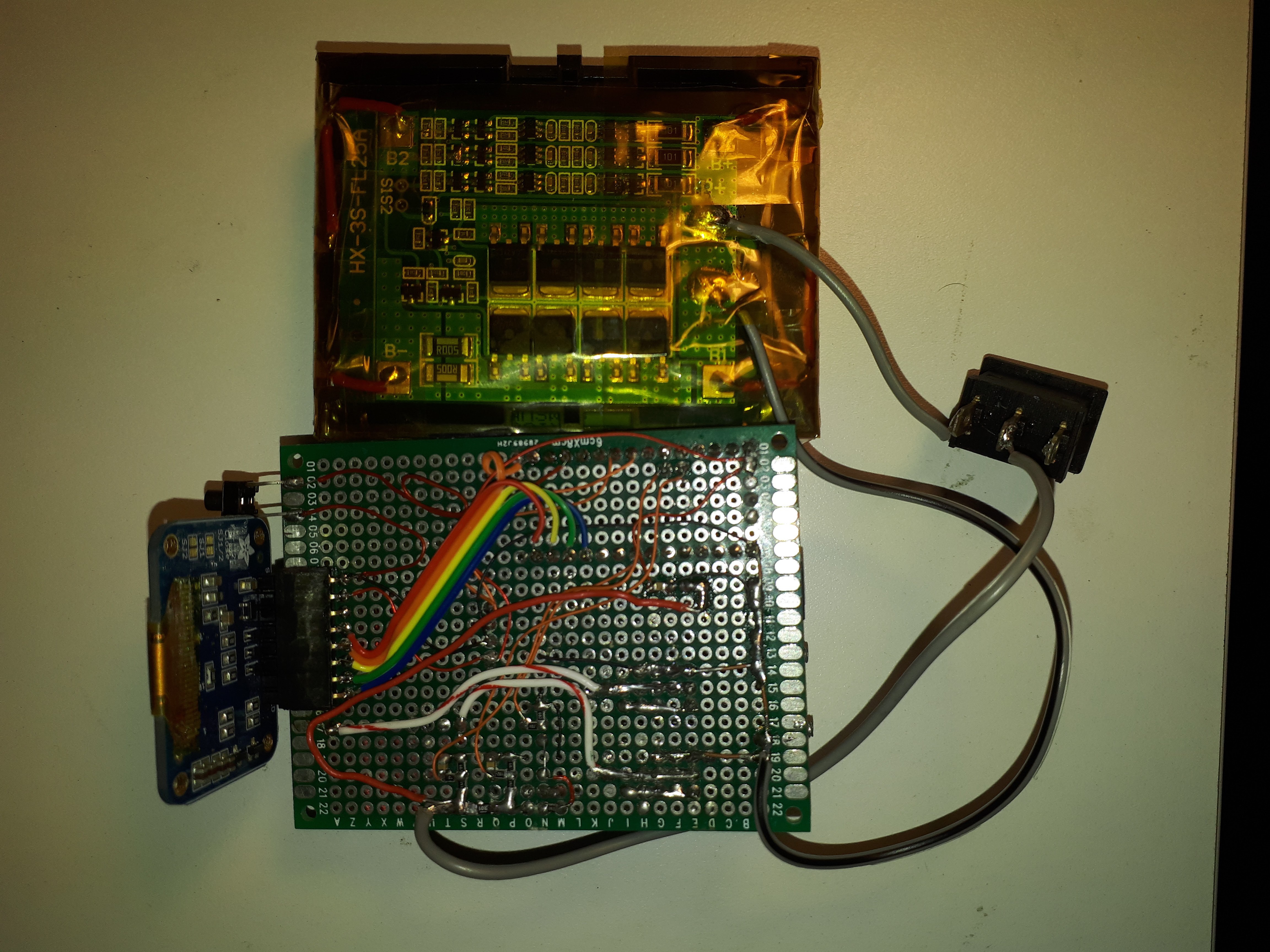
I've managed to get this thing mostly built! :) This is still very much a 'prototype' though, as I keep changing things as I go..

Anyway, I've had some ups and downs with this. The first time I hooked up the minimum induction circuit, everything worked great. Since moving to a perf-board, well, I've had some challenges :)

It boils down to a few errors on my side though..

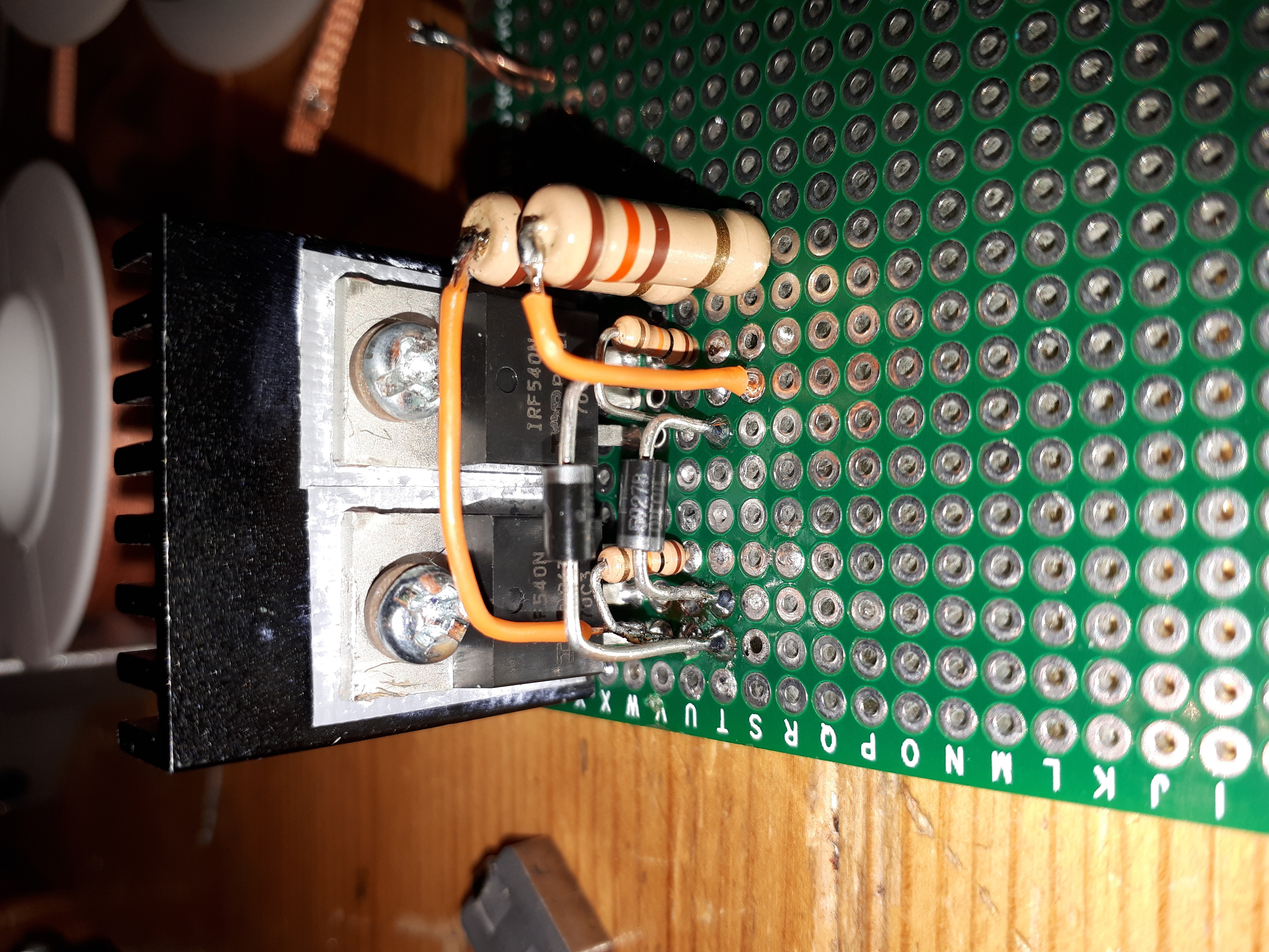
Can you spot one here?

8xQpr0w.jpg


Why yes, that big-ass pull up resistor is connected to the drain instead of the gate! I usually check things 10 times.. I guess 5 wasn't enough. I lost some sleep on this cause the first time I fired it up, it actually oscillated! Possibly due to a charged gate from diode leakage? Dunno.. Anyway, I then went on to build the PWM circuit, which obviously didn't work with that miss-connected pull-up. I lost some sleep on that one too :p Only after switching out transistors did I notice the resistor issue. Fixed and fixed. Everything was running coooool to the touch, and HOT on the vapcap! :)

I moved some components around, and changed those pull-ups while at it. I reduced their value from 140ohm (85 mA gate drive) to some smaller prettier 240ohms. This worked well with no vapcap in, but as soon as I had a vapcap in I blew my PWM driver (P-channel which switches V+). I assume it was due to the slow gate drive, causing lock-up of one of the N-channels while starting under load, and blowing my un-heatsinked P-channel (lazy me?). I'm all out of P-channels again but I'm filling up a mouser cart. I'm getting some better-suited components now though, after learning a lot about what this circuit likes and doesn't. I'll also drive the gates with different resistors (180 and 140ohm) to guarantee start-up. While I wait for those transistors I've still got way more to do..

Still on the menu:

* Differential analog conversion on the current sense resistor. Got precision Rsense and resistors for the dividers in my cart. I could probably do low-side current sense, though I don't want to mess with ground.
* Figure out buttons.. (capacitive touch works only while the oscillator is off.. will experiment more..)
* Add some more thermal sensors. I have some ds18b20's around, I'll attach them to the transistors for auto-shut down under fault condition detection.
* optical line-break sensor to detect insertion of VC.
* frequency detection. Maybe opto-coupler on coil. This will also be part of fault detection, and could possibly be the PID input. I't'll only work when the oscillator is on, so I could set the PWM minimum to, say, 1%, and sync up with the PWM timer.
* Low power sleep mode, watchdog timer, etc. Code is still all written just to get things working, and is still very much a WIP.
* Put it in temporary box till the case I ordered came. I got this one, and it should fit :)
* Notice the space left under the microcontroller? Yes, the VC can fit in there! I'll have to cut up a doob-tube to keep it in place.
* Put in a damn fuse already. I've ordered some polyfuses which should be suitable.

I'm thinking of putting a female USB socket instead of buttons, then taking a male receptacle and putting buttons on it. It'll look like a tiny usb dongle with two buttons on the top. I can then also use it as a backup USB charger :) Need to figure out how to work nicely the usb charging spec. This will mean that I'll have to cram a little buck converter in there to provide decent charging current/efficiency.


Any other ideas?

When this thing works, its awesome. It's a perfect companion for the VC. Specially once I get it working 100% reliably.

@Pipes @hardboiledfrog I'll be glad to share my findings with you guys. I hardly have time to build this thing though, between my job, two kids, and a 39 week preggo wife :) surprised I got this far (was in race mode..) though reducing gears now.. I'll try at-least draw up a schematic. hbf maybe you could design a board for this, and @Pipes could handle the manufacturing line? :)


mSNPKYg.jpg


mSNPKYg.jpg


yP7e04w.jpg


MoftEiG.jpg


P.S Just thought I may as well use both P and N for control, which would work as a double safety :) As the VCap goes into the tube and is detected by the IR line break, I'll turn on V+ with the P, do some sanity tests, and then PWM with the N. Will try it out sometime :)
 
Last edited:

Alexis

Well-Known Member
A little overdue update...

I've managed to get this thing mostly built! :) This is still very much a 'prototype' though, as I keep changing things as I go..

Anyway, I've had some ups and downs with this. The first time I hooked up the minimum induction circuit, everything worked great. Since moving to a perf-board, well, I've had some challenges :)

It boils down to a few errors on my side though..

Can you spot one here?

8xQpr0w.jpg


Why yes, that big-ass pull up resistor is connected to the drain instead of the gate! I usually check things 10 times.. I guess 5 wasn't enough. I lost some sleep on this cause the first time I fired it up, it actually oscillated! Possibly due to a charged gate from diode leakage? Dunno.. Anyway, I then went on to build the PWM circuit, which obviously didn't work with that miss-connected pull-up. I lost some sleep on that one too :p Only after switching out transistors did I notice the resistor issue. Fixed and fixed. Everything was running coooool to the touch, and HOT on the vapcap! :)

I moved some components around, and changed those pull-ups while at it. I reduced their value from 140ohm (85 mA gate drive) to some smaller prettier 240ohms. This worked well with no vapcap in, but as soon as I had a vapcap in I blew my PWM driver (P-channel which switches V+). I assume it was due to the slow gate drive, causing lock-up of one of the N-channels while starting under load, and blowing my un-heatsinked P-channel (lazy me?). I'm all out of P-channels again but I'm filling up a mouser cart. I'm getting some better-suited components now though, after learning a lot about what this circuit likes and doesn't. I'll also drive the gates with different resistors (180 and 140ohm) to guarantee start-up. While I wait for those transistors I've still got way more to do..

Still on the menu:

* Differential analog conversion on the current sense resistor. Got precision Rsense and resistors for the dividers in my cart. I could probably do low-side current sense, though I don't want to mess with ground.
* Figure out buttons.. (capacitive touch works only while the oscillator is off.. will experiment more..)
* Add some more thermal sensors. I have some ds18b20's around, I'll attach them to the transistors for auto-shut down under fault condition detection.
* optical line-break sensor to detect insertion of VC.
* frequency detection. Maybe opto-coupler on coil. This will also be part of fault detection, and could possibly be the PID input. I't'll only work when the oscillator is on, so I could set the PWM minimum to, say, 1%, and sync up with the PWM timer.
* Low power sleep mode, watchdog timer, etc. Code is still all written just to get things working, and is still very much a WIP.
* Put it in temporary box till the case I ordered came. I got this one, and it should fit :)
* Notice the space left under the microcontroller? Yes, the VC can fit in there! I'll have to cut up a doob-tube to keep it in place.
* Put in a damn fuse already. I've ordered some polyfuses which should be suitable.

I'm thinking of putting a female USB socket instead of buttons, then taking a male receptacle and putting buttons on it. It'll look like a tiny usb dongle with two buttons on the top. I can then also use it as a backup USB charger :) Need to figure out how to work nicely the usb charging spec. This will mean that I'll have to cram a little buck converter in there to provide decent charging current/efficiency.


Any other ideas?

When this thing works, its awesome. It's a perfect companion for the VC. Specially once I get it working 100% reliably.

@Pipes @hardboiledfrog I'll be glad to share my findings with you guys. I hardly have time to build this thing though, between my job, two kids, and a 39 week preggo wife :) surprised I got this far (was in race mode..) though reducing gears now.. I'll try at-least draw up a schematic. hbf maybe you could design a board for this, and @Pipes could handle the manufacturing line? :)


mSNPKYg.jpg


mSNPKYg.jpg


yP7e04w.jpg


MoftEiG.jpg


P.S Just thought I may as well use both P and N for control, which would work as a double safety :) As the VCap goes into the tube and is detected by the IR line break, I'll turn on V+ with the P, do some sanity tests, and then PWM with the N. Will try it out sometime :)
Phew, at least some of that was in "english"! Just kidding. Im sure Pipes and a few others know exactly what you mean.
Apart from your brilliant technical know-how, a terrific effort with such a busy life, and worthy of applause in my book.:clap:
Ps. I really hope your son is doing okay with the heart troubles. Best wishes.
 

rz

Well-Known Member

Thanks. He has a kind of Fallot type DORV, meaning the wall dividing the two ventricles isn't complete, so blood flows between them. The aortic valve over-rides the partition and receives some of the blood that's meant to go to the lungs, sending it back to his body. This results in a varying degree of declination of his oxygen levels, and needs repair. Fortunately his heart appears to be pumping away nicely and hopefully he won't need any immediate intervention, and it can wait a few months. I'm so glad that Israel has two hospitals that perform similar, and even much more complex surgeries on a daily basis. People come here from all around the world, and they are both about 40 minutes drive away. Also fortunate that we have socialized medicine, and my largest expenses so far have been on parking! This is incredible in light of the full array of tests that we've performed. We've met a lot of doctors, and even his surgeon, and feel that he's in great hands, so we're optimistic and excited to meet the little bugger already :D
 

Alexis

Well-Known Member
Thanks. He has a kind of Fallot type DORV, meaning the wall dividing the two ventricles isn't complete, so blood flows between them. The aortic valve over-rides the partition and receives some of the blood that's meant to go to the lungs, sending it back to his body. This results in a varying degree of declination of his oxygen levels, and needs repair. Fortunately his heart appears to be pumping away nicely and hopefully he won't need any immediate intervention, and it can wait a few months. I'm so glad that Israel has two hospitals that perform similar, and even much more complex surgeries on a daily basis. People come here from all around the world, and they are both about 40 minutes drive away. Also fortunate that we have socialized medicine, and my largest expenses so far have been on parking! This is incredible in light of the full array of tests that we've performed. We've met a lot of doctors, and even his surgeon, and feel that he's in great hands, so we're optimistic and excited to meet the little bugger already :D
That sounds very hopeful, and yes you are so lucky with your situation. Itis amazing when skilled people can perform practical miracles within the medical establishment. I am really big into healing with alternative remedies to offer additional support. I hope I may be of some help one day for the betterment of his health with some useful ideas, but hopefully that wont ever be necessary. Best of luck for the remainder of the pregnancy and birth.
 

hardboiledfrog

tinkerer
I moved some components around, and changed those pull-ups while at it. I reduced their value from 140ohm (85 mA gate drive) to some smaller prettier 240ohms. This worked well with no vapcap in, but as soon as I had a vapcap in I blew my PWM driver (P-channel which switches V+). I assume it was due to the slow gate drive, causing lock-up of one of the N-channels while starting under load, and blowing my un-heatsinked P-channel (lazy me?). I'm all out of P-channels again but I'm filling up a mouser cart. I'm getting some better-suited components now though, after learning a lot about what this circuit likes and doesn't. I'll also drive the gates with different resistors (180 and 140ohm) to guarantee start-up. While I wait for those transistors I've still got way more to do..
nice! you have made great progress! :clap::tup:
I like the 240 ohm gate drives better, I don't think you need more than this. ZVS failure is usually caused by inadequate power supply but your battery pack should have been good enough. :hmm:
maybe the p-channel has too much of a voltage drop across it?
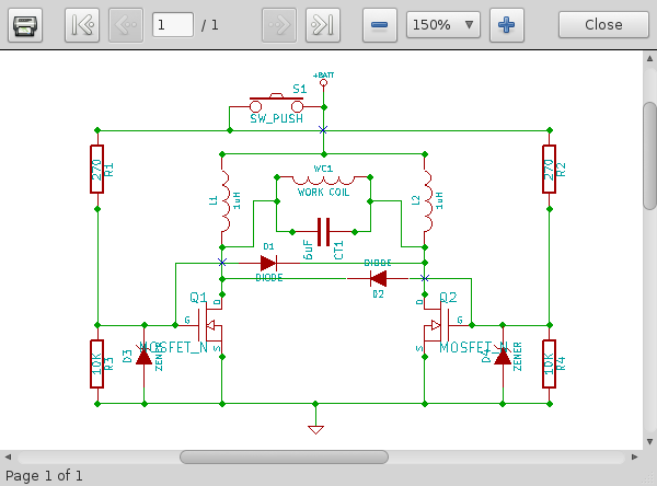
maybe your PWM frequency is too high? in a relatively slow heating application like this I think slower time-proportional control is better, I'm using a 1250mS period. you can also PWM the ZVS by switching power to the ZVS gate drive resistors. I use a small reed relay (to replace the push button in the schematic) currently for isolation but you could use a pnp transistor or a small p-channel in place of the push button to enable the gate drives and use your large p-channel as just a main power supply switch.
Vhcdr0r.png


* Differential analog conversion on the current sense resistor. Got precision Rsense and resistors for the dividers in my cart. I could probably do low-side current sense, though I don't want to mess with ground.
these work really nice for power monitoring: INA219 High Side DC Current Sensor Breakout
you could change to or parallel a smaller value sense resistor to increase the current capability.

Wow @rz that is something! Me think is a little too much for only replacing a lighter to heat vapcap (personally i like to KIS ;) ), but maybe this is the core of a whole new vape?

:popcorn:

good idea! I would like to see someone do an induction vaporizer project. you could heat air drawn through rolled up titanium mesh in a glass tube heated by induction.
@rz has a great base to build on. :nod::tup:

oh, and best wishes with your family, you're lucky you don't live in America where similar health issues could easily bankrupt you. :o:mad:
 

rz

Well-Known Member

Me too! TBH, been exhausted lately, and I can't even recall exactly what I did last time it died. However, I'll keep experimenting till I get something reliable! Taking a break from the oscillator for a bit (Too much flux fumes!) while I play with some other things, and get more parts in! Damn, prototyping can get pretty expensive :p Kudo's @Pipes, less than a benjamin for what you get is keeping it real for the peoples here :tup:

PWM was set to 100Hz, with 8 bit resolution. So each duty cycle was 10 millis, enough for about 1600 oscillations at 160Khz, or about 6 cycles per bit. I was switching the whole BATT point in your schematic. This actually worked pretty well, and the p-channel was cool, hence it was left without a heat-sink, probably why I lost so many of them .. :hmm:. I scoped out VGS and and it seemed (marginally) within spec even with ringing. I probably should have put that TVS on already though..

I had previously tried switching just the chokes, and leaving the resistors high. This also worked pretty well, and was actually interesting since the ~100mA through the resistors was enough to cause oscillation! Albeit at a very low voltage. Not sure exactly how, maybe by feeding through D1/D2?. Anyway, as soon as a workpiece was in, it was immediately dampened by the extra load (Maybe could be used to detect work piece insertion?).

I have an INA219 breakout. It's a bit too big though. I considered maybe trimming the board to stick it somewhere. I got some 0.01Ohm 1% last time already. I then thought of using a 16 bit ADC breakout with PGA since I'm familiar with it already, but $$$.. and hey look, the teensy can measure differentially, and the teensy 3.2 even has a PGA! I'm playing with it now. My voltage divider isn't so accurate (0.1%'s for my dividers in my current mouser order), and I couldn't be bothered to figure out how unbalanced it is at 64x gain, so I averaged some measurements, compared them to my multimeter readout, 2-point linear equation, and it seems OK for now :) seems to measure my 40ma usage now, and the -370mA I was getting while charging. Will see how it detects ~10 Amps when I get the oscillator back up.

Anyway, I like the idea of just using a pnp for the gate resistors. I'll experiment with that when I get back into it! :) I could then still use the p-channel to power up the chokes, and run the PWM on the gates. This would also be a double safety :)

Great idea for the induction vape! :) It's really not far from that capability already.

BTW, I used JB-weld ("steel reinforced epoxy", which is actually just iron powder in epoxy) to make the glass tube to IR sensor mount. Its actually perfect since, well, there isnt really an air-path so not toooo concerned, it's ferrous! and it doesnt conduct, so it doesn't get heated. Could probably encase the whole work coil in it, and throw in some aluminum fins to cool it off.. overkill, but why not? :D Not yet though...

@Pipes I used some reclaimed 4.7uF SMD inductors, they're standing upright beneath that red heatshrink. I have the two large chokes that I wrapped, not sure about their value, and @hardboiledfrog even used 1uF (reasoning?) even though ~50~150 is recommended. Seemed to work. I have some other values on order.

Thanks. Any day now! May be tomorrow :D

Oh, and I found an old little sparkfun box with some buttons. It has these button pads in a few colors and this navigation switch. For my proto, I'll probably use that red silicone button pad. The round on in the middle. It actually has 4 buttons on it, great for navigation, and for a firm hold down to get busy mode! :D

Hm. Need to get some sleep...

P.S I left out the 12v zeners. Since the driving voltage is always from the battery, it shouldn't ever exceed 12.6v (a little higher while charging), way within spec. And due to ZVS, there shouldnt be any inductive kickback. Maybe there was due to PWM and a one in a million (every 3 hours? may be right..) killed it all. I'll just go ahead and stick them back in next time I get this going :)
 
Last edited:

hardboiledfrog

tinkerer
Damn, prototyping can get pretty expensive :p Kudo's @Pipes, less than a benjamin for what you get is keeping it real for the peoples here :tup:
yeah, no kidding! if the war department knew how much funds I've diverted to R&D she would surely go nuclear! :uhoh::o

This actually worked pretty well, and the p-channel was cool, hence it was left without a heat-sink, probably why I lost so many of them .. :hmm:. I scoped out VGS and and it seemed (marginally) within spec even with ringing.
if it's cool to the touch then a heat-sink is not needed. I think it's probably voltage spikes that's killing your p-channels.

I then thought of using a 16 bit ADC breakout with PGA since I'm familiar with it already, but $$$.. and hey look, the teensy can measure differentially, and the teensy 3.2 even has a PGA!
not that expensive at banggood: http://www.banggood.com/search/ads1115-16-bit/2152-0-0-1-1-44-0-price-0-0_p-1.html
I :love:what Lady Ada does and I do support her with some purchases but for what she's paying for those boards she's making a killing and my R&D budget isn't that big. :)

Anyway, I like the idea of just using a pnp for the gate resistors. I'll experiment with that when I get back into it! :) I could then still use the p-channel to power up the chokes, and run the PWM on the gates. This would also be a double safety :)
:tup::)

Great idea for the induction vape! :) It's really not far from that capability already.
:nod: yes, great idea @Andreaerdna. you are almost there and I know it would be real popular here. :nod:

BTW, I used JB-weld ("steel reinforced epoxy", which is actually just iron powder in epoxy) to make the glass tube to IR sensor mount. Its actually perfect since, well, there isnt really an air-path so not toooo concerned, it's ferrous! and it doesnt conduct, so it doesn't get heated. Could probably encase the whole work coil in it,
I'm really surprised the JB-weld wasn't affected by the work coil but I see it's only 10% -20% iron
https://www.whatsinproducts.com/files/brands_pdf/10657_10012002 MSDS J-B Weld Resin and Hardener.pdf
so too small an amount I guess. :shrug:
I think you will find this interesting: http://fluxtrol.com/

@Pipes I used some reclaimed 4.7uF SMD inductors, they're standing upright beneath that red heatshrink. I have the two large chokes that I wrapped, not sure about their value, and @hardboiledfrog even used 1uF (reasoning?) even though ~50~150 is recommended. Seemed to work. I have some other values on order.
I like these surface mount inductors because of the high current capability and very small package. inductor value seems to be pretty flexible for the ZVS drivers IME and for the low duty cycle of my induction flashlight mod they don't get very warm.
http://www.coilcraft.com/xal1010.cfm
Coilcraft makes an excellent product and is very generous with samples. :brow::D
 
Last edited:

Alexis

Well-Known Member
Out of interest, have any UK members here received orders from the US via slow boat?
Im just anticipating how long it might be before my jarhead arrives.

I cant vape for another 3 weeks yet, it would be fab if it gets here around thenm(Pipes sent it end of last week).
Im patient, just getting excited!
 

Alexis

Well-Known Member
Any thoughts about the new "M" vapcap with a stainless steel tip? Is the "Jarhead" going to heat the "M"?
Just a thought, it will be fun finding out. Doc
My thoughts exactly. I see no reason why not. Whatever property it is of the Ti tips that makes them work better with the induction heaters than the OG, must be present to some extent in the stainless steel tips.

I mean Im presuming it has at least something to do with design, and the metal element, but we will have to wait and see if there are any significant differences between steel and titanium for intents and purposes.

Should be interesting, we might learn something.
 
Top Bottom