VapCap Induction Heater for Desktop and in Car Use

Prophecy

Well-Known Member
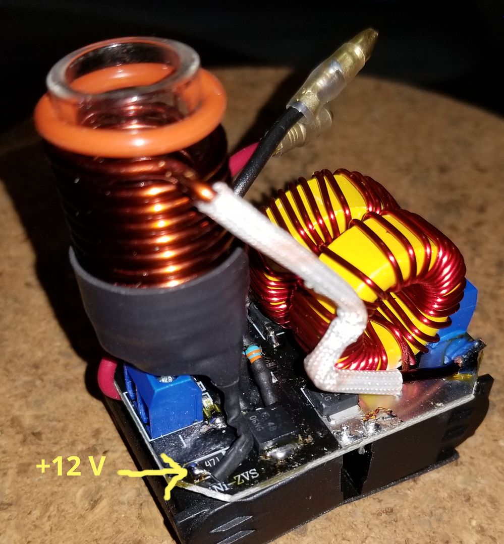
Today my tactile switch in the glass tube from my skeletor IH broken down, the whole plastic from the switch went down see the picture.
Must say I used the IH daily for 15 months multiple times a day, but in the last week the switch had a wobbling feeling too, always when I pushed my vapcap in the glastube I had to move my vapcap back and forth while pushing down to engage the IH.

Is there any fix to resolve this issue?

In this moment I'm glad that I have also a Portside Mini :)


Prophecy

Well-Known Member
Those are fairly common switches if you know how to solder a new one in. Personally I might wire in a separate remote switch.

The switch itself works, I'll try to make something that has the same diameter of the glass cylinder and the same height of the plastic pusher with a tip at one end so that it then rests on the button on the circuit board that should then work again.
 

Pipes

Addicted DIY Enthusiast
Accessory Maker
The switch itself works, I'll try to make something that has the same diameter of the glass cylinder and the same height of the plastic pusher with a tip at one end so that it then rests on the button on the circuit board that should then work again.
You have the right idea there. You need to bulk up the original button such that it's close to the diameter of the tube. Then it should self-center the pin over the click plate. Now a layer of high temp silicone cut from an oven mat or mitt to just bigger than the ID of the tube so it will rest on top of the button keeping it in place. Just my initial thinking. Let me ponder a bit more. :hmm:
 

Chopper37

New Member
From FAQ:
12 volt Power Supply or Substitute
The substitute will increase click speed as it is more powerful at 8 amp rating.
:science:
My friend just got a Portside mini from you and I would like to order one from you please

You have the right idea there. You need to bulk up the original button such that it's close to the diameter of the tube. Then it should self-center the pin over the click plate. Now a layer of high temp silicone cut from an oven mat or mitt to just bigger than the ID of the tube so it will rest on top of the button keeping it in place. Just my initial thinking. Let me ponder a bit more. :hmm:
chris Gallagher recommended speaking to you to get a Portside mini
 
Last edited by a moderator:
Chopper37,
  • Like
Reactions: Madri-Gal

Prophecy

Well-Known Member
The switch itself works, I'll try to make something that has the same diameter of the glass cylinder and the same height of the plastic pusher with a tip at one end so that it then rests on the button on the circuit board that should then work again.

You have the right idea there. You need to bulk up the original button such that it's close to the diameter of the tube. Then it should self-center the pin over the click plate. Now a layer of high temp silicone cut from an oven mat or mitt to just bigger than the ID of the tube so it will rest on top of the button keeping it in place. Just my initial thinking. Let me ponder a bit more. :hmm:

My skeletor is working again I have take a 6mm thick ground leather, punched 2 discs out from them with a 17 mm punch hole and then I made a hole in the middle of both that I can attach them stacked together with a slightly longer and bigger in diameter wooden nail, had to grind down a little of the 17 mm diameter and that works perfect now. :rockon:


desspina

Member
Cool quick testing setup. However, I hope that your not using as a permanent device like that. It has disaster written all over it.
1/You should have a non-latching switch for manual operation.
2/Cardboard is not a good enclosure for obvious fire risk reasons.
3/Need something under the coil so the VC doesn't burn the bottom.
I recommend you tighten the radius down some. I'm using an ID of 17mm.
Good luck and well done!

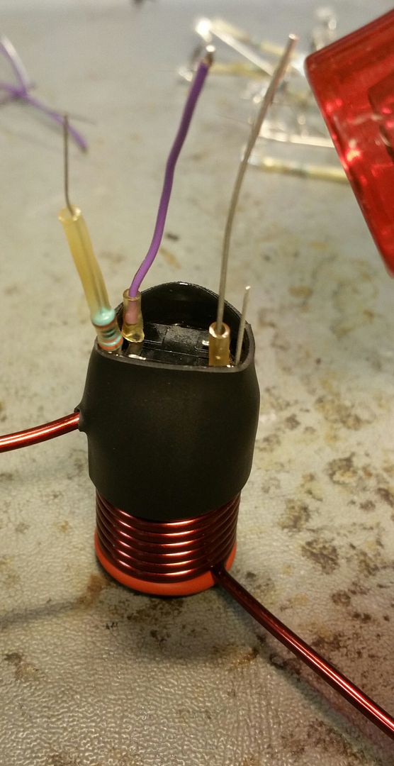
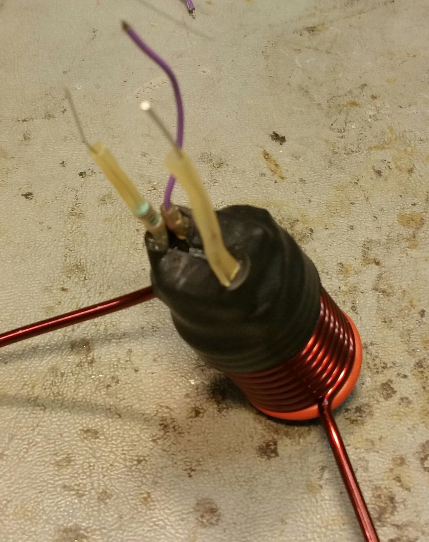
So here is a little inside to the making of the coil assembly.
I start with making the LEDs and tach switches to be pre formed and wired.


Then I pretube all the coils.


Get what's needed all together.


Drop in the LED assembly.


Drop in the tach switch with the positive leg beside the tach switch wire which I left bare.


Apply heat from heat gun or lighter.


While still hot, push the sides over and align the tach switch to center.


Twist and solder the two + leads together.


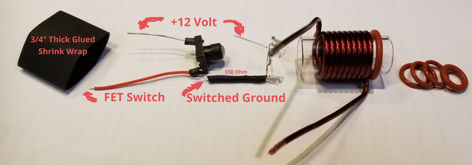
Followed by some thin shrink wrap. And that's it. From here, there are 3 leads from the LED/switch cluster. One for switched ground to activate the LEDs, one for the trigger from the Tach switch and the last one goes to V+. This part is the same for all my units. The coil legs are bent different, pending on orientation and model.


:science:
Hello Pipes, i have a question about the 3 leads..i can't seem to figure out where exactly they come on the mosfet...the purple one connects to V+in, the one with the resistor connects to trig/pwm..and the ground? I would really appreciate it if you would help me out :rolleyes: Thanks
 
desspina,
  • Like
Reactions: Madri-Gal

Pipes

Addicted DIY Enthusiast
Accessory Maker
This post will help with where the wires go. :science:
In keeping with the open-source spirit for these drivers, I put together a few pictures for the DIYers that want to clone my modification methods.
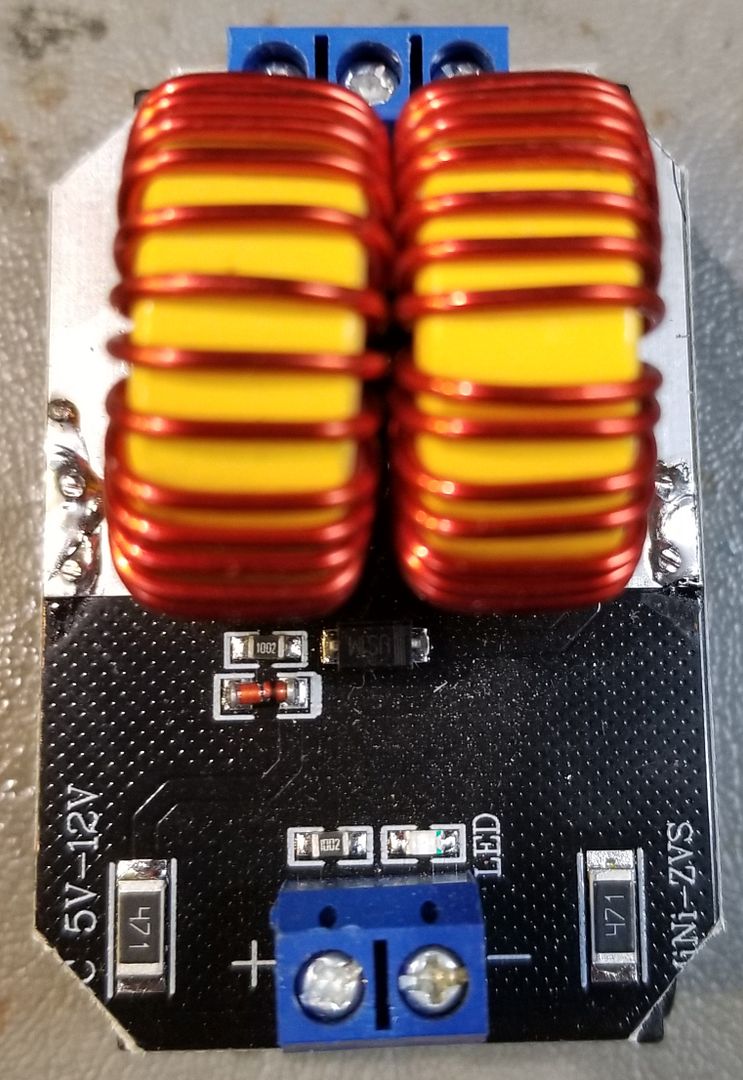
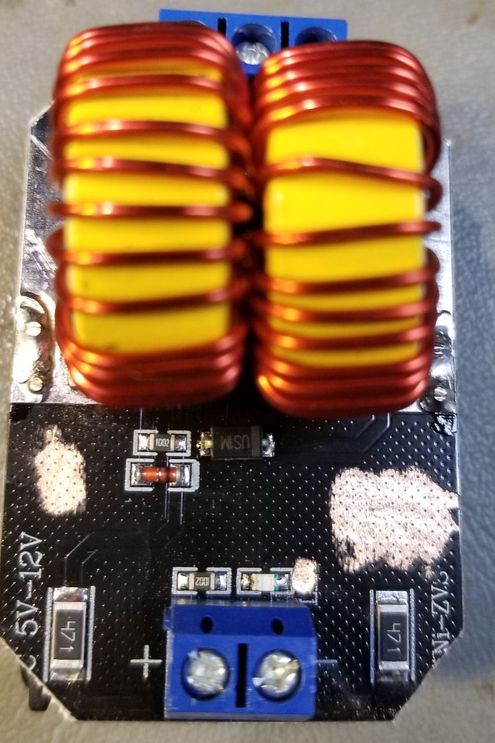
It starts with doing some mods to the driver board.

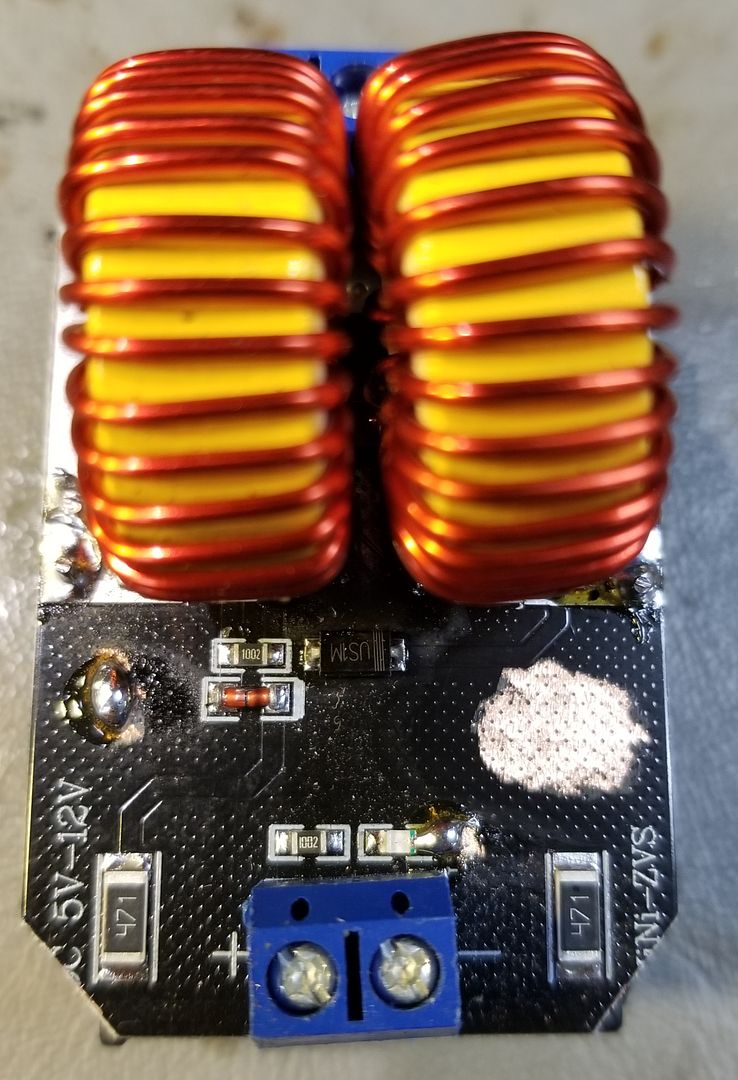
The first thing is a thorough inspection for cold solders, badly mounted or backward components. Then I snip the corners so it will fit into my enclosures. Not needed for other enclosures. I now found a supplier that has good FETs but I always add solder to the FET legs as they can look pretty dry.


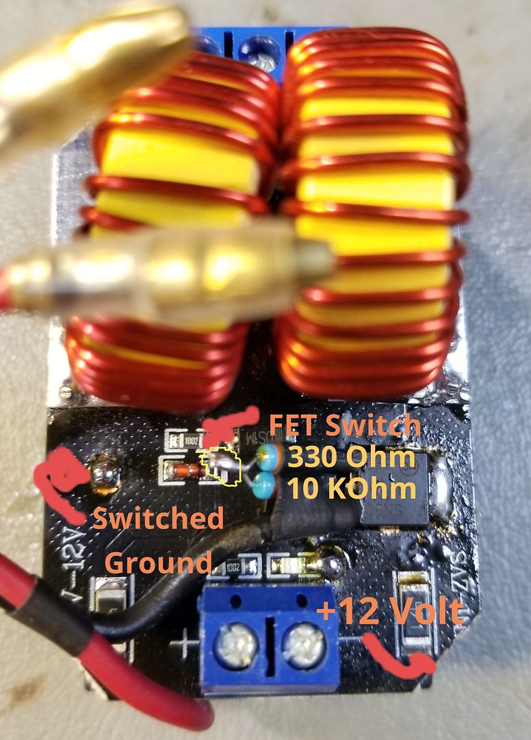
The next thing I do is grind off some enamel in particular areas that need to have solder added. Left spot is for adding the ground wire from the LEDs in the activation tube. The small area above the blue connector is to ground the foil that we are going to use as ground. Depending on the board manufacturer, some is already at ground potential but other manufacturers have left this foil floating. The larger spot is for mounting the FET switch to provide the soft power switch capability.


Here the solder is added for the LED ground wire and solder jumpering the floating foil to the ground which is the end of the little LED that comes on the board.


This is the modified driver board with FET mounted. The main 12 volt "in" is the same as before any modifying but the ground now goes to the source of the added FET. Once the FET is switched on via the tactile switch, the output will become ground potential. Thus turning the unit on.


And finally, the work coil setup. Those two 12 volt wires get twisted and soldered together once the tube is assembled. Thus has 3 wires coming from it. 12 volt, FET activation signal and ground for the power on LEDs.


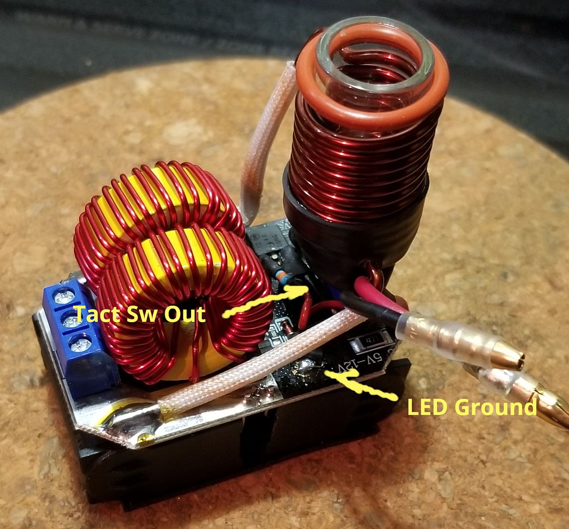
Here is where the connections are from the tube mechanism to the board. This side shows the ground and the tact switch out to the resistor bridge to the FET switch.


And this side shows where I steal the 12 volts from. It is present on either board side on the same resistor.

That's about it in a short tutorial. The rest is time and patents along with some soldering skills.

Enjoy! And have fun! :science:
 

Bad Ocelot

Well-Known Member
I have an og portside & a portside mini, both still going strong :love: However the little feet on the bottom & the magnet on top of the portside have all come off. Well, the mini was fine until last week when my significant other used it for a few minutes & someone lost them all lol. Anyway I did a little searching through the thread but couldn't find any info about good replacements for these and/or a good adhesive to use, especially for the magnet. Any help would be appreciated!
 

Pipes

Addicted DIY Enthusiast
Accessory Maker
Here is a link to the ones I use. I'm sure there are similar ones at the hardware store.
The magnet and gauge are held on by double-sided tape. I think carpet tape will work as well. If you want to get bold, crazy glue is an option but must be careful. It's best to put a drop on some wax paper and use a pin to apply a dab or two from the drop using the pin to transfer an extremely small amount. :science:
 

TommyDee

Vaporitor
How clean did you want it? I have 2 options if 11.1V is enough. 14500IMR (700mah) and 3x 18650 (3500mah). The holders come apart for charging individual cells.

eBay has all the Chinese quick wire solutions for battery management systems. Best advise to date is cell holders with tabs, not springs. You get 5 for near-nothing. Mod the case to grab the center cell. Very tight fit on unprotected cells.
 

swieder711

Well-Known Member
How clean did you want it? I have 2 options if 11.1V is enough. 14500IMR (700mah) and 3x 18650 (3500mah). The holders come apart for charging individual cells.

eBay has all the Chinese quick wire solutions for battery management systems. Best advise to date is cell holders with tabs, not springs. You get 5 for near-nothing. Mod the case to grab the center cell. Very tight fit on unprotected cells.

So something like this
https://rover.ebay.com/rover/0/0/0?mpre=https://www.ebay.com/ulk/itm/232964243759

Along with a battery holder for 3 18650s and some connectors for charging and supplying power would do it?
 
swieder711,
  • Like
Reactions: Madri-Gal

BirdFisher

Member
You have me stumped as should work the same.
However, there is a plan "B".
I stopped using those FET boards and have been using a single IRF540N FET and a 10 K resistor instead. Takes less room and more secure. The 10 K resistor goes between the gate and drain. Zoom in on the picture and you'll see it at the bottom of the FET. I cleared a spot on the board which is all ground and soldered the FET through the hole directly to the board. This is the new main ground for the circuit. The input ground is the source of the FET and the gate is the new "trigger" input. I've marked the connection points of the two circuits below. They have identical function. The Ground connection is for the power indicator LED inside the tube.
(img removed)
Enjoy and good luck! :science:

Hi Pipes! BTW I never thanked you, I bought a PSM from you a while ago, and it's still going strong! Fantastic design, actually a reference, kudos.

Since then I built a number of DC models that work OK, but recently I came across a batch of those bad ZVS drivers, on which the FET seem to fail. I have a bunch of them now.

I tried to re-build one, using this online tutorial video but no luck (a MOSFet burns, and the coil stays cold).

1575991023.jpg


Can you confirm this parts list, knowing that I'm using a 60Watts (12v 5A) PSU?

2x IRF540 MOSFET
2x 330nF Capacitor (I'm using the two 600VAC / 1200VDC found in the drivers)
2x UF4007 Diode
2x 220Ω Resistor
2x 0.1mH Inductor (same, salvaged the two coils off the driver)

Could you also confirm that the wiring diagram is OK?

1575991387.png


If you could find the time, that would be really cool, if not it's OK, you must be pretty busy.
 
BirdFisher,
  • Like
Reactions: Madri-Gal

Pipes

Addicted DIY Enthusiast
Accessory Maker
This power source thing has come up a few times. I stopped making as the 25 amp BMS is a little high rated for our task but works fine. I also had to decide on which unit to fill the position for a portable as I need to keep the lineup to a minimum to keep the production process going smoothly.
An off the self option for external power would be an emergency battery booster but would need the correct cabling. Some come with the correct cable. (5.5x2.1mm)
Or a big RC battery and add your own BMS, charge cable and XT connectors to make the load wire from. As well as a couple of power pigtails for charging/outputting.
Have fun! :sherlock:
 

Pipes

Addicted DIY Enthusiast
Accessory Maker
Hi Pipes! BTW I never thanked you, I bought a PSM from you a while ago, and it's still going strong! Fantastic design, actually a reference, kudos.

Since then I built a number of DC models that work OK, but recently I came across a batch of those bad ZVS drivers, on which the FET seem to fail. I have a bunch of them now.

I tried to re-build one, using this online tutorial video but no luck (a MOSFet burns, and the coil stays cold).

1575991023.jpg


Can you confirm this parts list, knowing that I'm using a 60Watts (12v 5A) PSU?

2x IRF540 MOSFET
2x 330nF Capacitor (I'm using the two 600VAC / 1200VDC found in the drivers)
2x UF4007 Diode
2x 220Ω Resistor
2x 0.1mH Inductor (same, salvaged the two coils off the driver)

Could you also confirm that the wiring diagram is OK?

1575991387.png


If you could find the time, that would be really cool, if not it's OK, you must be pretty busy.

I don't think UF4007 is a SCHOTTKY Diode but rather a standard diode. Therefore, I do not think it will oscillate correctly if at all. Also, the wire gauge you are using is too thin.
You need a schottky type diode like a 1N5819 or from Ali.
Also, you are using the tact switch for the main switch. Might last 2-3 times. You either need a heavy-duty switch or go FET switch as discussed in the post you linked to above.
Good luck! :science:
 

Nooweed

New Member
So after lurking for a long while. I’ve got my Basic IH working.

Added in a mosfet. Still works

Next up is adding batteries, and then I can squeeze it into a case.

Batteries are confusing me as I’ve never really played with 18650s (plenty of experience with 12v systems in jeeps)

If I buy one of these....
https://rover.ebay.com/rover/0/0/0?mpre=https://www.ebay.com.au/ulk/itm/293104752069

And one of these...
https://rover.ebay.com/rover/0/0/0?mpre=https://www.ebay.com.au/ulk/itm/123867878266

Solder them together in 3s. Then I can use a toggle to switch between charging from my original wall socket (do they want a specific current, or does the BMS look after that?) and then toggle for it to be my supply power. Sorry for the questions, I’ve googled too much and am now overthinking and confusing myself.
 
Top Bottom