VapCap Induction Heater for Desktop and in Car Use

TheThriftDrifter

Land of the long vapor cloud
Thanks for the replies. I appreciate it.

The wire length/gauge for adjustment of the time to click sounds like a good starting point for me. What makes you aim at 8 seconds for your goal?
 

Pipes

Addicted DIY Enthusiast
Accessory Maker
Any faster and it's pushing things power-wise and IMO, not as flavorful on the first puff. Some like 10 or more seconds to ensure the goods get a good heat soaking before you inhale. 8 seconds is a good starting point. It will be interesting to hear back from you once you play some. :science:
 

TommyDee

Vaporitor
@TheThriftDrifter - Also think about this... your well charged car battery, at least one in a functional car, will run up at around 13.8V. I thought you had a volt meter on your bench setup. You might check that battery just to know where it is when fully charged. Also, I'd be careful about DIY'n packs and charging. Nearly took out a brand new TV that way once :\

@Pipes - Great info :tup:
 
Last edited:

TheThriftDrifter

Land of the long vapor cloud
I've been learning about how to charge and maintain lead acid batteries, got an old deep cycle one that I restored, gonna use that instead of the car battery. Want to use the nicad pack as a more portable power source.

Also, I'd be careful about DIY'n packs and charging. Nearly took out a brand new TV that way once :\

Thanks for the heads up.

Will keep you posted.:nod:
 
TheThriftDrifter,
  • Like
Reactions: endof3d

TheThriftDrifter

Land of the long vapor cloud
I did a couple of quick tests with my IH setup, the load was an empty Dynavap M, the batteries and connectors being the only hardware difference between the tests. I did my best to keep the load insertion depth the same across each heat cycle.

A. 12v lead acid car battery.

State of charge - 12.56v
Current draw at idle - 1.32A
Current draw with load - 5.3/5.8A
First heat cycle to click - 5.5 sec
2nd - 4.1 sec
3rd - 3.5 sec


B. 14.4v nicad cordless drill battery pack.

State of charge - 14.9 v
Current draw at idle - 1.54A
Current draw with load - 4.4/4.7A
First heat cycle to click - 9.5 sec
2nd - 7 sec
3rd - 7.5 sec

The NiCad was slower than I thought it would be, with less draw at load than the LA. Nothing got unusually hot, although when i have time i'll run the test again with more cycles. At the moment it looks like the NiCad might be a suitable power supply.

I also learnt that if you put the loaded, running IH too close to your mobile phone(was using it as a stopwatch) It makes the phone do weird things. :shrug:
 
Last edited:
TheThriftDrifter,
  • Like
Reactions: Planck

TommyDee

Vaporitor
Those are some crazy findings @TheThriftDrifter . I just got my std IH from China today. Seems China is starting to recycle solder. All the SMT components barely had any solder; I was able to pull the power connector out without heat! The coils had no fillet on the top side. It seemed the FET's were not well bonded to the ground plane. Did a major rebuilding of the board and now that I have some of your most excellent data, I think I can finish this project. 18awg wire on the input seems about right.

Anyone try to glow a halogen bulb in the coil yet?

Who could have thought that up'ing the voltage would reduce the output? What wire gauge did you use on the NiCD setup @TheThriftDrifter ?
 

TheThriftDrifter

Land of the long vapor cloud
Not sure of the wire gauge, i used scavenged parts, ill have to check. I'm newish to electronics and i was a bit confused by the results, i will do a re test with different connectors to the batteries and might buy a second multimeter. I did wonder if it might be because the car battery is designed to crank out alot of power all at once.
 
TheThriftDrifter,

Pipes

Addicted DIY Enthusiast
Accessory Maker
To check where the voltage is dropping you need to measure at the load input as well as at the battery output while you are inserting the VC. These numbers are the important ones.
If the wiring is identical, the drop is at the battery indicating a lower "C" rating which means a higher internal battery resistance.
The idle current is higher because there is no voltage sage without load. The lower current draw while under load indicates the voltage is dropping somewhere besides at the load. Most likely in the battery and will be causing some internal heat. Keep an eye on this!
Interesting results. :science:
 
Pipes,
  • Like
Reactions: TommyDee

TommyDee

Vaporitor
You caught onto where I was going @Pipes :cheers:

Whoohoo! A new blister! Damn this things works well. Yep, floating around 1.4 amps idle. A little over 3 amps with a jeweler's screw driver.

I need to go make a basket for the VapCap.

48978399042_1a6dfaaa81_z.jpg


...and what do you know, what I thought was a teflon rod... wasn't! :doh:

So I got creative. PortSide... meet SidePort :smug:

48978719832_2759f10701_z.jpg


Just kidding of course, but I had a hard time figuring out what to use that wouldn't go up in smoke. Turns out this particular little glass vile fits perfectly with squished 3mm Teflon tube. It fits snug and it is quite functional. You can adjust the vial for insertion depth to boot.

Thought I'd post this in case others where having trouble finding something to 'make due'

48977983558_8612f8547e_z.jpg

:bigleaf:

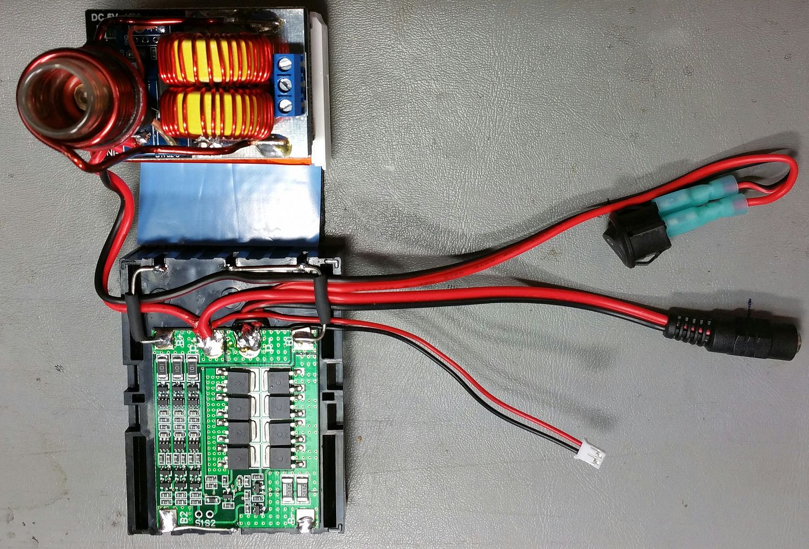
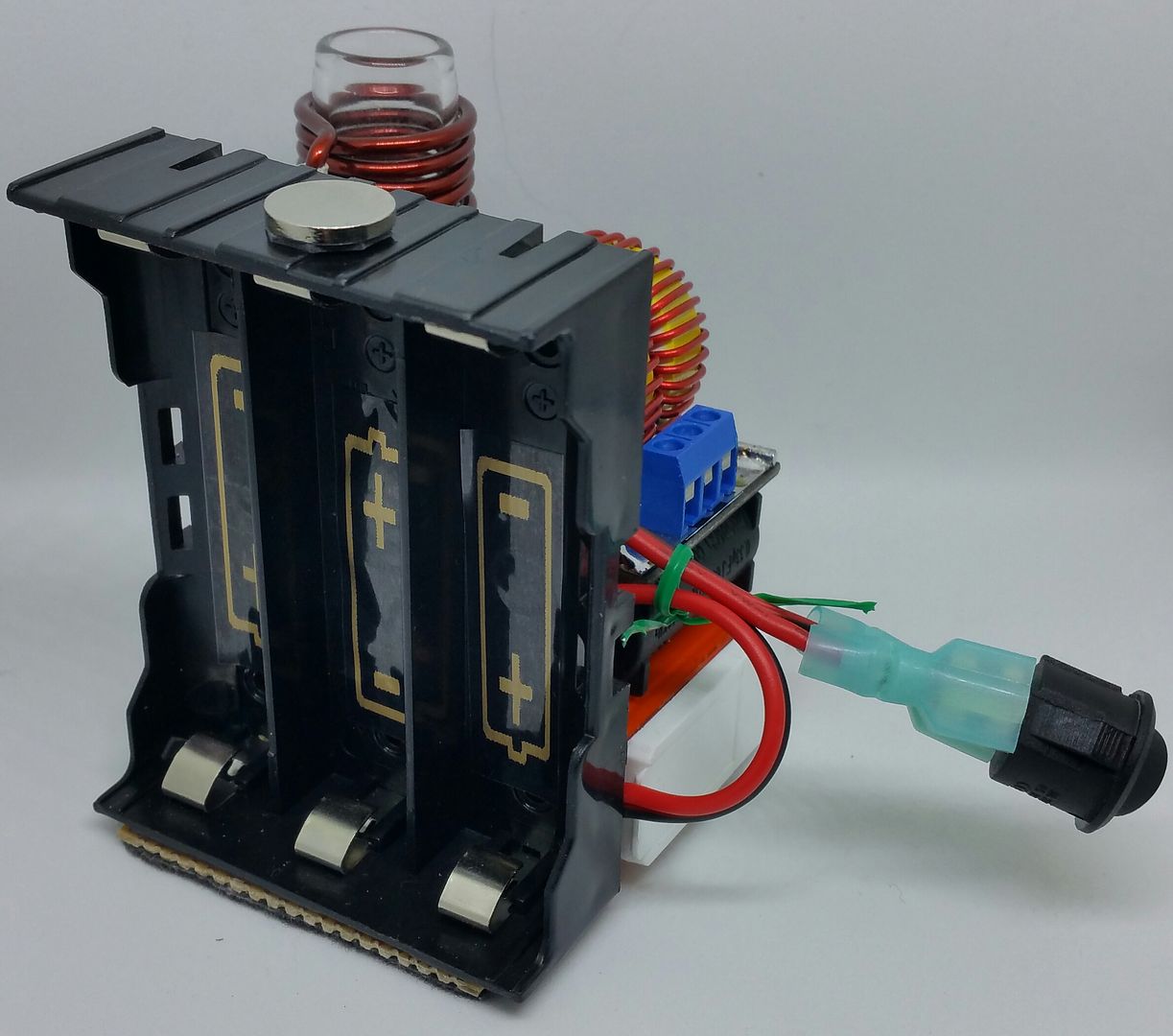
Basically this is a fairly stable platform. I put 11.1V against it with 3x 18650's and a switch. Serves me well for the moment as I'm still relegated to the great outdoors for my medication.

I've got another one coming from Cali. I'll get a little smarter with it on when it comes to making it a belt-carry device. Definitely need to find my Teflon rods so I can machine some cups!
 
Last edited:

TheThriftDrifter

Land of the long vapor cloud
What's the ID and OD on your vial? Did you leave the coil as it came or did you rewind it? Some nice beefy wire from your power supply!

To check where the voltage is dropping you need to measure at the load input as well as at the battery output

I'm not quite sure how to do this.
 
Last edited by a moderator:
TheThriftDrifter,

TommyDee

Vaporitor
I'd like the ID a little smaller but this one is just under .6" OD and very thin. You want something in the 1/2" ID or slightly smaller. The idea is centering the VapCap in the coil. the better the fit, the more parallel to the coil.

The coil that came with the unit is basically a 3/4" ID wind. I got .735" ID consistently. Took the OD of the vile, ID of the coil, divide by 2 and I get the spacers I needed. In this case about .07" which the 3mm tube made up for very well. I don't know yet how hot the coil gets but Teflon it the safest choice. Viton o-ring material may be a good second for having contact with the coil.

Those are some 16awg or 14awg silicone wires from a RC heli motor. They kind of popped out of a box saying "Use Me!".

The o-rings around the caps double as skid-proof feet until I make a box for it.

As to measuring voltage drop, just measure at the input terminals on the IH board and then at the battery. the difference is the voltage drop. Using two meters is obviously preferable.
 

Pipes

Addicted DIY Enthusiast
Accessory Maker
What's the ID and OD on your vial? Did you leave the coil as it came or did you rewind it? Some nice beefy wire from your power supply!
I'm not quite sure how to do this.
The glass tube I use is 16mm OD and I made a jig from dowelling that is just a tad under 16mm so the tube twists in tight. I twist or tighten up the coil by twisting around the dowelling which adds about 1 1/2 extra wraps of the coil. I snap away about 1 wrap and end up with 9 1/2 loops total. :science:
 

TommyDee

Vaporitor
The glass tube I use is 16mm OD and I made a jig from dowelling that is just a tad under 16mm so the tube twists in tight. I twist or tighten up the coil by twisting around the dowelling which adds about 1 1/2 extra wraps of the coil. I snap away about 1 wrap and end up with 9 1/2 loops total. :science:

Indeed, wrapping your own coil provides more options for the glass. I need to go visit our local vape shop and see what they have for glass. This unit I made will work for the short term. I'll have another this weekend to tking a lot harder on.

Also need to go source a BMS. Found a really nice closeout on some 18500 Li-Ion cells. 3x 18650's works out nicely for 7 seconds to the click.

I do need to tilt that coil a little :whip:
 

TommyDee

Vaporitor
BMS will be a study but I suspect it can be made simpler depending on the charge time that is reasonable. Individual cell "chargers" are fairly compact at under an amp. I can see a number of ways to implement that. I just need to learn how other systems do this, primarily laptop solutions. They have very little dedicated circuitry for this.

Good point on the battery clip. Indeed, the wire gauge and poor conductivity of steel wire springs just makes them fuses. I'll probably make the cells into packs with charge leads back to the main circuit board. I'm still aiming for that side-carry solution.

I had also recalled my other curiosity with regard to the induction heater; that being the Direct IH Vape. [DIHV]. This should be fun. I have no doubt that this will work where power is not an issue. But I will say that this idea has the potential of the fastest heating vape out there. Getting control over power levels will be a challenge. This leads me to one other question and it may be my misunderstanding of the circuit or how it was explained. From what I understand, the traditional fly-back circuit perfectly tuned would draw very little to no power. Was that just a brain fart or is that the ZEN state of an IH circuit with no load?

Edit: looks like a lot of options for BMS. Easy to duplicate on a new layout as well.
I think I just found my new favorite battery store: https://www.18650batterystore.com/default.asp
Also looks like an 18500 solution is quite limiting sad to say.
Maybe a massive cell with a boost converter :freak:
 
Last edited:

TommyDee

Vaporitor
I finally got some proper use of the IH. With the cap near the end of the coil, fully inserted, I got 10 seconds to the click with 11.1V and some serious drop across connections, contacts, and an under rated switch. Using a wooden stem so all the heat was gathered in one region. Definitely some power hits.
Now to package this a little better. And the wooden stem makes the side port work just fine. :brow:
 

TheThriftDrifter

Land of the long vapor cloud
Thinking about buying a power supply/adapter for my 12v module.
What would you all recommend? 5, 6, 8, or 10 amp? Most likely get it from aliexpress as the retail prices here are 4-6 times more expensive.

Cheers
 
TheThriftDrifter,

Pipes

Addicted DIY Enthusiast
Accessory Maker
Should go 8 amp with an un-tested supply as many are finicky when working at their upper current limit.
There is a link to an 8 amp unit in my FAQ as well as the proven good 5 amp unit. :science:
 
Top Bottom