VapCap Induction Heater for Desktop and in Car Use

nachooo

Well-Known Member
You have me stumped as should work the same.
However, there is a plan "B".
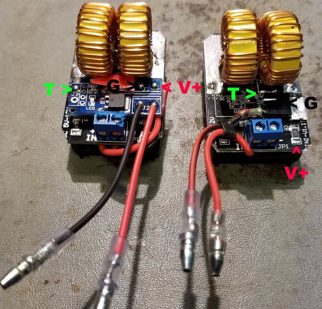
I stopped using those FET boards and have been using a single IRF540N FET and a 10 K resistor instead. Takes less room and more secure. The 10 K resistor goes between the gate and drain. Zoom in on the picture and you'll see it at the bottom of the FET. I cleared a spot on the board which is all ground and soldered the FET through the hole directly to the board. This is the new main ground for the circuit. The input ground is the source of the FET and the gate is the new "trigger" input. I've marked the connection points of the two circuits below. They have identical function. The Ground connection is for the power indicator LED inside the tube.


Enjoy and good luck! :science:
Thanks, as english is not my native language it cost me a little to understand..but finally I think I get it..also I dont know nothing about electronics, in fact is the first time I have been soldering something to a circuit board…
So for me to understand, I pick the new mosfet, remove the black paint of the board until metal appears in the correct place, sold the metal base of the mosfet as in the pic, put a 10 K resistor between the gate and the (drain or source???)

The ground (negative) of the battery should be solder to the source in the mosfet...and the positive from battery connected to the (in + ) in the Little blue conector...

I Will not use any led light inside the tube..
I undertand that one of the wires from the momentay switch must go to the trigger wich is the gate in the mosfet… But where should the other wire from the switch must be attached?

Is this all I have to do? Do I need to do more connections?

Sorry and thanks for your patience….I am very noob at this..I had to look at the wiki what is a mosfet and its parts etc...I have started to like electronics since this little project:)
 
nachooo,

Pipes

Addicted DIY Enthusiast
Accessory Maker
Most probably you mean between the Gate and the Source pins .
This is done to bring the Gate to ground in order to switch off the MOSFET and avoid
any unwanted /accidental capacitative driving of the Gate .

Also it would be a good idea to place a Gate resistor ( 100R to 1K ).
Ringing (aka parasitic oscillation) can be induced by the gate capacitance in series with the trace's / wire's inductance and will lead the MOSFET to dissipate lot's of power,
'cause it will not turn on quickly enough ,thus the current at drain/source path ,combined with the rather high drain-source impedance will heat the device up. A low value resistor will dampen the parasitic oscillation .

http://irf.custhelp.com/app/answers/detail/a_id/215

:2c:
Yes, I stand corrected, I met gate and source, a slip up on my part. The end pins, so easy to wrap a resister in place.
You are also correct about having some gate resistance. However, haven't run into any switch bounce issues. Also, since it's just being used here as an off/on switch and not an oscillator, the parasitic oscillation should not be an issue..? Adding another resister is not a big issue but if not needed... If you have a case for me to update please PM me your recommendations. ;)
Good stuff!! :science:
 

stardustsailor

Well-Known Member
Accessory Maker
The bouncing of the switch contacts is not an issue of great importance-if there's a gate resistor installed .The Mosfet still fully switches ON & OFF .It is ( almost ) like applying a very short in duration PWM signal to the Gate .
But ,if there's not a Gate resistor present ,switch contact bouncing
(and possible picked up ambient noise ) will only make things even worse.

The Gate resistor -if missing- can pose a threat to the MOSFET .
The Mosfet Gate has a certain capacitance ( with the Source & Drain ).
The wire or trace (in case of a pcb ) that is connected to the Gate pin of the MOSFET ,
has a certain inductance (very small ,but it's there ) .
The longer the wire that is connected to the gate and/or the more wrapped ,
the worst .
Together ,they form a LC oscillating circuit.
That circuit once the switch is "activated" it can cause what is called as " ringing " .
They oscillate (the wire's "inductor " and the gate's "capacitor" ).
That causes the MOSFET to switch ON slow enough .
Since the ZVS module can draw up to 10 A ,that slow switching can overheat the MOSFET
and maybe -just maybe -even fry it .

Placing a resistor of low value ( 100R -1K ) between the wire's "inductor" and the gate's "capacitor " dampens any parasitic oscillation .

The Gate resistor should be placed after the 10K "gate grounding " resistor ,as if otherwise
a "voltage divider "circuit is formed and at the gate is applied lower voltage than the supplied .
Not a very important detail ,but better be safe ( than sorry ) when working with MOSFETs .

@nachooo

Debouncing filter circuitry -inside gray rectangle- can be omitted .


Cheers.
:peace:
 
Last edited:

nachooo

Well-Known Member
The bouncing of the switch contacts is not an issue of great importance.
It is ( almost ) like applying a very short in duration PWM signal to the Gate .

But the Gate resistor -if missing- can pose a threat to the MOSFET .

The Mosfet Gate has a certain capacitance ( with the Source & Drain ).
The wire or trace (in case of a pcb ) that is connected to the Gate pin of the MOSFET ,
has a certain inductance (very small ,but it's there ) .
The longer the wire that is connected to the gate and/or the more wrapped ,
the worst .
Together ,they form an LC oscillating circuit.
That circuit once the switch is "activated" it can cause what is called as " ringing " .
They oscillate (the wire's "inductor " and the gate's "capacitor" ).
That causes the MOSFET to switch ON slow enough .
Since the ZVS module can draw up to 10 A ,that slow switching can overheat the MOSFET
and maybe -just maybe -even fry it .

Placing a resistor of low value ( 100K -1K ) between the wire's "inductor" and the gate's "capacitor " dampens any parasitic oscillation .

The Gate resistor should be placed after the 10K "gate grounding " resistor ,as if otherwise
a "voltage divider "circuit is formed and at the gate is applied lower voltage than the supplied .
Not a very important detail ,but better be safe ( than sorry ) when working with MOSFETs .

@nachooo

Debouncing filter circuitry -inside gray rectangle- can be omitted .


Cheers.
:peace:
Thanks...I understand now...last pic is perfect :)
I understand that if I solder the mosfet the way Pipes told before...the drain gets connected to the inductor module ground and is not needed to connect the drain throught the ground blue piece connection...
 
Last edited:

stardustsailor

Well-Known Member
Accessory Maker
I understand that if I solder the mosfet the way Pipes told before...the drain gets connected to the inductor module ground and is not needed to connect the drain throught the ground blue piece connection...
:tup:
Exactly.It also helps to the MOSFET 's cooling ,
althought cooling is not really necessary when the MOSFET operates as a switch.

Also it makes a more stable and secure contact .
Something that is obligatory with MOSFETS-as with the rest of electronic components .

Helps also retaining a small size / volume of the build.

Actually ,you can cut off the second pin ( Drain ) .
 
Last edited:

nachooo

Well-Known Member
:tup:
Exactly.It also helps to the MOSFET 's cooling ,
althought cooling is not really necessary when the MOSFET operates as a switch.

Also it makes a more stable and secure contact .
Something that is obligatory with MOSFETS-as with the rest of electronic components .

Helps also retaining a small size / volume of the build.

Actually ,you can cut off the second pin ( Drain ) .
Thanks again..I have a last question…
When I changed the big coils for the little ones, I noticed that the coils were connected and this link were also connected to the positive input of the induction board ...so I join my little coils and used a wire to connect that union to the positive input...soldering point…
Should I change this conecction in some way?...or leave it as it is?
Thanks again
 

stardustsailor

Well-Known Member
Accessory Maker
Thanks again..I have a last question…
When I changed the big coils for the little ones, I noticed that the coils were connected and this link were also connected to the positive input of the induction board ...so I join my little coils and used a wire to connect that union to the positive input...soldering point…
Should I change this conecction in some way?...or leave it as it is?
Thanks again
As long as the wire is kept short lengthwise and thick enough, there should not be a problem.
Take care for the wire -inductors connection not to be contacting (shortimg with ) anything else .

PS :
Some thoughts regarding your issue.
Since both the LEDs are ON ,that means that
power is delivered to the (modified )ZVS IH module via the MOSFET switch module.
But it also seems that the IH module won't start oscillating .
That is weird enough .

If there's not any bad solder joints ("cold " ones ) or screw-post connections ,
then most probably it has something to do with the modified operating frequency .
Which in your case it has increased far from the OEM setting ( ~ 200 kHz ) .

Still,that alone does not explain why the module works fine without the MOSFET switch ...
:hmm:
High frequency E/M noise pick -up ?
Quite possible .

Do a small test if you wish .
Connect the MOSFET switch to the modified IH module .
Then wrap the MOSFET switch module with an insulating material
( paper tape ,plastic tape ,electric tape , food membrane ,heat shrink tube ) .
Then wrap again the insulated MOSFET module with aluminium or copper foil or tape .
Does it work this way ?
 
Last edited:

nachooo

Well-Known Member
As long as the wire is kept short lengthwise and thick enough, there should not be a problem.
Take care for the wire -inductors connection not to be contacting (shortimg with ) anything else .

PS :
Some thoughts regarding your issue.
Since both the LEDs are ON ,that means that
power is delivered to the (modified )ZVS IH module via the MOSFET switch module.
But it also seems that the IH module won't start oscillating .
That is weird enough .

If there's not any bad solder joints ("cold " ones ) or screw-post connections ,
then most probably it has something to do with the modified operating frequency .
Which in your case it has increased far from the OEM setting ( ~ 200 kHz ) .

Still,that alone does not explain why the module works fine without the MOSFET switch ...
:hmm:
High frequency E/M noise pick -up ?
Quite possible .

Please ,do a small test if possible.
Connect the MOSFET switch to the modified IH module .
Then wrap the MOSFET switch module with an insulating material
( paper tape ,plastic tape ,electric tape , food membrane ,heat shrink tube ) .
Then wrap again the insulated MOSFET module with aluminium or copper foil or tape .
Does it work this way ?
I just did it and while it was covered nothing happens...then I uncovered and it worked!!! but...it need almost 30 seconds to make the dynavap click… then I try to replicate and without touching anything...it did not work again…. then I disconneced the fet module and make a direct conection..without twitch and voila..in 10 seconds the click sounded nicely… Weird...a mistery...
 
nachooo,

Dick Emery

New Member
OK thanks for the parts list but has anyone got a build guide for a 'non' battery operated version for a complete electronics noob?
 
Dick Emery,
  • Like
Reactions: dboxy

dmisc

Member
A switching power supply will recover from hiccup mode by itself either automatically
or when the PSU is switched OFF and powered back ON .
You do not have to do anything special .

It is the connected device that "trips" the protection of the PSU .
(and the PSU's " self recovery mode " that makes the blue LED blink )
That means that the ZVS module has a short circuit somewhere .
At best case , one of the Magically Obliterated ,Smoke and Fire Emitting Transistors is fried .


After watching vids on youtube on how to test these things, I think I found the culprit. If I just purchase a IRF54ON FET, I can just Swap them out?


H3YkssxiAY-iowQNo9loNQ_rgUNaZk1nR51rOh7XVp5-brvYES4fKjYrNgDbM9NkEh-9sJuDQRX8ZnrcFTYK1DqeUpA5hkvt4DSFqS-FVbuHmp4VzZr8xAi_SP0qFMPgZsAPCMY2HDH4gqOOtVp0NU3K83ANTFlzQ0WWbfUirmEdk-djgYG3ppsgl_uR5HoharVqjRHiZQqAU03Zq4IIq9GwATNoE2BCJPgXXJpqVfKW80pvcLgk3zfQHoAhkcOD0Rt_PzuxT9XcgNWvwWS0kvoM1kcPXC5Yh-lQaSAgWYpVejaG3pjpW5EJiQxacal0iAAgYEdnYRrvL4FekI6NBjmwDXNjLvuFi97EoWawsWHtdfR3i_ZepqHORy3kP_p4_aGzaMTIFYbqfh2DfDXooHX-q0g0Ry9zqi_oSR4XGL4qmGjMv36kchonsuBw3pNYpaTHShevfWrT-fYWgoz0hX1n7C2T0pVkJbthCh3b76F4AR8Y6mJtY-k0CMSlE5oHPQx2OvAabSI61rau9M2RPv-1OWmDBBiTId0_gPPqNDf_ix3si2EoLAv8sEd0D1Xcr5EBkt-OOxou2jEkZyJsmcce0CUbbGHKraXpTgLe4jebp4pU281CzSctBqmRzcQm=w541-h961-no
 

stardustsailor

Well-Known Member
Accessory Maker
After watching vids on youtube on how to test these things, I think I found the culprit. If I just purchase a IRF54ON FET, I can just Swap them out?

The MOSFET IRF540N comes only in TO220A package which is quite large to fit in place of the fried one .
https://www.infineon.com/dgdl/irf540n.pdf?fileId=5546d462533600a4015355e396cb199f

You will need a MOSFET that comes at the DPAK ( aka 369A ) package .
Furthermore ,the replacement MOSFET should have these characteristics :
Vdss = 30 V - 100 V
Id = 20 - 100 A
Rds= less than 50 mOhms ( m Ω ) . The less ,the better !


Some types of MOSFETs you can use :

https://www.onsemi.com/pub/Collateral/NTD4806N-D.PDF

http://www.onsemi.com/pub/Collateral/NTD24N06-D.PDF

http://www.onsemi.com/pub/Collateral/NTD4815N-D.PDF

https://www.diodes.com/assets/Datasheets/ZXMN6A25K.pdf

Search for more :
https://gr.mouser.com/Semiconductor...ransistors/MOSFET/_/N-ax1sf?P=1z0xumnZ1z0y3zr

May the Force be with you .

:science:

P.S. : I strongly suggest that you should replace BOTH the original MOSFETs
with two new ones OF THE SAME TYPE .
 
Last edited:

dmisc

Member

stardustsailor

Well-Known Member
Accessory Maker
@stardustsailor ah okay. Im getting confused...lol. On your "VapCap DIY Induction Heating : Bits 'n' pieces", you posted this as replacement.

IRF540N
( 33 A ,100 V ) A really "tough" FET ! :
https://www.infineon.com/dgdl/irf540n.pdf?fileId=5546d462533600a4015355e396cb199f

I am totally new to this stuff, and trying to learn as much as I can. In the picture that I posted, where I circled, is that the 30N06?

Thanks in advance.

Yes ,that was before I've actually got one of these ZVS IH modules in my hands .
I thought that the MOSFETS were of the TO220 package ,but they are not .
They are some mystery chips of the DPAK package .
Yes ,that's one of the two MOSFETS ,circled at your pic.

The original MOSFETS most probably are of some N06G type .
You can notice the "N06G " mark at the pic
:
03_595_14_16_1024x1024.jpg

https://www.sainsmart.com/products/5v-12v-zvs-induction-heating-power-supply

A a very good replacement MOSFET is the NTD4806N
https://www.onsemi.com/pub/Collateral/NTD4806N-D.PDF

As also the NTD20N6N:
http://www.onsemi.com/pub/Collateral/NTD20N06-D.PDF

Another good option is the NTD5803N
https://media.digikey.com/pdf/Data Sheets/ON Semiconductor PDFs/NTD5803N.pdf

And many more :

https://www.st.com/resource/en/datasheet/std150n3llh6.pdf

https://www.onsemi.com/pub/Collateral/NTD5867NL-D.PDF

https://www.onsemi.com/pub/Collateral/NTD4805N-D.PDF

https://www.onsemi.com/pub/Collateral/NTD4813NH-D.PDF

https://www.mouser.ec/datasheet/2/308/NTD4804N-D-1387842.pdf

http://www.farnell.com/datasheets/86014.pdf

https://media.digikey.com/pdf/Data Sheets/ON Semiconductor PDFs/NTD4979N.pdf

https://www.insidegadgets.com/wp-content/uploads/2013/11/NTD4963N.pdf
 
Last edited:
stardustsailor,
  • Like
Reactions: Hogni

Pipes

Addicted DIY Enthusiast
Accessory Maker
I made a short video for you guys stuck with bad driver boards and not sure about how to go about changing the FETs out. This is the easiest method I've found if they have never been changed before. If they have to replaced again, the use of solder wick is needed to clean up excess solder from the legs before lifting them is attempted. A very hot pointy iron is a must for this. I set mine all the way to 850 degrees and just be quick.


stressed

Well-Known Member
@Pipes

howdy.

i have the portside and the mini. both have the same recharge cable (thingy). the cable for the mini doesn't work for some reason so i use the portside one for both.

slight problem, the recharge part that plugs into an electric socket gets ridiculously hot. like you can't hold it tight without thinking, this thing is going to burn my hand or blow up. i often unplug it before the heaters are fully charged because the thing gets so hot.

is there another recharge cord thing that i can buy for these heaters?

it makes me nervous.


oh and which one can be used to take hits when it's plugged in??

also, i noticed that the portside seems to recharge whether its on i or o on the on off switch. the mini only recharges when it's on i. a bit confusing. is this normal? i typically charge the portside on o.
 
Last edited:
stressed,

Pipes

Addicted DIY Enthusiast
Accessory Maker
With exception to the failed charger, all you say is normal. The charger does get very hot while in it's peak charge mode but cools down as the charge gets close to complete. However, no enclosure deformities have been reported from getting "too" hot.
Either unit can be used while charging. Just ensure the battery isn't completely depleted and has some charge before using.
The wiring in the PSM is changed such that the switch needs to be on while charging so that the charging port doesn't have voltage while in the off position and safer in your pocket. The PS port is hot while the switch is off.
The easiest place for replacement chargers is Amazon. Just search "12.6 volt charger". The voltage makes the search pretty specific.
;)
 

ragnorak71

Well-Known Member
well now

my portside mini arrived today and as interesting the techno babble above is, truth is I dont really get it. what I do get is how fast this package arrived (im in uk) how well built and easy to use it is and my whole dynavap experience has made me moist in ways only us adults understand.

i said to pipes in pm every single aspect of this deal has been spectacular and I recommend it so much

forgive the hyperbole but fuck me this thing is great, you may resume the babble i am off to touch myself
 

phattpiggie

Well-Known Member
Accessory Maker
@Padriano sent me over his spare Mighty adapter for a play with and it works great.
It's quick and no overheating of the adapter.
Tiny little adapter compared to the other high amp ones and about 2 sodding meters of cable.
Cheers Padriano.
A couple of tiny shards of shatter on cotton.
 

supreme86

Well-Known Member
Hey guys I was wondering if you could help me. I'm wanting to build my own battery powered IH but I am unsure of which parts I need from pipes barebones selection and if there is any soldering involved. Thank you in advance
 
supreme86,
Top Bottom