DIY Induction Heater Builds and References

webtroter

Well-Known Member
Hi everyone,

I'm currently planning an IH build powered from USB-PD. I ordered most of the parts I will need, but I wondered if you could provide me with insights if anyone did something similar.
I might try the half-pint circuit, but I'm not sure if the mini-zvs I bought is compatible.

I was also wondering if it's possible to separate the coil from the zvs board.

I have just realized that I don't have a glass tube. :(
 
webtroter,

TommyDee

Vaporitor
You have a good plan. HalfPint is doable but a bit of a challenge. Go back to page 13 for some insights.

USB-C can do up to 5 amps and 100 watts is more than sufficient to run an IH. The DC - DC inverter will make up for the rest. The real question is - will the USB-C power supply know what to do when it sees the appropriate load?
 
TommyDee,

webtroter

Well-Known Member
You have a good plan. HalfPint is doable but a bit of a challenge. Go back to page 13 for some insights.

USB-C can do up to 5 amps and 100 watts is more than sufficient to run an IH. The DC - DC inverter will make up for the rest. The real question is - will the USB-C power supply know what to do when it sees the appropriate load?
This is the magic of USB-PD :)

You select the voltage by soldering a bridge on the board Dumb me, I was looking at so many board I bought the one with a button :( . It will still work, I will only need to find a way to make sure it always tries to negotiate 20V
 
webtroter,
  • Like
Reactions: TommyDee
This is the magic of USB-PD :)

You select the voltage by soldering a bridge on the board Dumb me, I was looking at so many board I bought the one with a button :( . It will still work, I will only need to find a way to make sure it always tries to negotiate 20V
I'm not sure about the one you ordered, but when I was learning about USB-PD via youtube some of the button ones could be set to only negotiate certain profiles.
 
RandomFactor,

webtroter

Well-Known Member
I'm not sure about the one you ordered, but when I was learning about USB-PD via youtube some of the button ones could be set to only negotiate certain profiles.
Yeah, that's what I understood of the poorly translated description. thank you for validating my thought
 
webtroter,

TommyDee

Vaporitor
Looking forward to your implementation of USB-C. Would love to see a robust solution for charging and for powering. What is available as 100 watt power sources that will drive the USB-PD?
 
TommyDee,

webtroter

Well-Known Member
What is available as 100 watt power sources that will drive the USB-PD?

I use something similar to this (in spec and tech) : https://www.amazon.ca/MINIX-Charger-Charging-Adapter-Compatible/dp/B0892K4ZHH for my laptop

And I bought a usb-pd tester with my parts to test the outputs and load of everything

As for my implementation, I think I read somewhere here that the halfpint could do ~65 watts. I happen to have a 65w usb-c battery pack that I could use as portable power source. If that just doesnt work, then I'll think a bit more.

I'm dreaming about super capacitors and being able to charge them with simple 5v usb or maybe 1s 16850 or other format
 
Last edited:
webtroter,

TommyDee

Vaporitor
HalfPint will do 100 watts. Your 65 watt supply may or may not fold back if the power is over-drawn. Don't use the power supply to limit power. The IH will draw what it needs and the power supply should supply it with ease. Some take care of this by shutting down gracefully and others just burn out prematurely. You can adjust HalfPint with coil wire length and coupling. You should be okay but do measure the power demand from the IH on a 12V supply to know if the 65 watt supply is sufficient.
 
TommyDee,

blastfromdapast

New Member
In the pic right above where it says: "And when were done with that we make sure the whole trace is tinned well with solder;" how did you make that trace and can one just jump a wire between the two MOSFETS? Maybe I'm not getting it but can you explain that operation please?
Thanks in advance
Doug
 
blastfromdapast,

blastfromdapast

New Member
Right above the following sentence is another view of the trace between the MOSFETS. How did you make that connection:
Once the sub-assembly is soldered in place, congratulations, you've build a HalfPint. Thanks. I tried leaving a msg earlier but did not see it.
Doug
 
blastfromdapast,

TommyDee

Vaporitor
Hey Doug - I expose the trace between the two connected legs of the FETs with a hobby knife. I solder a wire to the newly exposed trace.20200922_175148 (2).jpg
 
Last edited:
TommyDee,

blastfromdapast

New Member
Hey Doug - I expose the trace between the two connected legs of the FETs with a hobby knife. I solder a wire to the newly exposed trace.
I'll be darned but can you see the trace or do you just gently scrape it as I can see o sign of it on the surface of the PCB. My eyes are not what they used to be but I can only try to follow the picture and hope I find it I guess. Even with a strong light I cannot (held behind it, I can see no sign. Should I just try follow the picrures best I can? Thanks for the quick return
 
blastfromdapast,

TommyDee

Vaporitor
It is visible. The black is a thin epoxy. I am careful to make sure the adjacent copper is not exposed.

This extra effort is highly optional. The negative input terminal will work just fine. I do this for several reasons one of which is minimal power losses.
 
TommyDee,

TommyDee

Vaporitor
Some are laid out a little differently. Pop up a picture and I'm sure I can recognize the layout.
 
TommyDee,

blastfromdapast

New Member
Some are laid out a little differently. Pop up a picture and I'm sure I can recognize the layout.
this going to sound nutty in this day and age but I have neither camera nor a cell phone. I am a real throwback on the phone, I just never had the use and the camera I did have is somewhere but unless I get lucky I have not a clue where it is. The COVID restrictions up here only allow 1 person in your home and HE is worse and does not ever have a computer. Sorry for that but I will look. It was a module that came when I ordered 4 and the coil on this one was completely cold soldered in two places, so I can afford to lose it but again sorry about no pic.
Doug
 
blastfromdapast,

TommyDee

Vaporitor
No worries. Completely understand. Know that those two legs of the FETs are the negative input.
 
TommyDee,

TommyDee

Vaporitor
I remove the connectors and the pad for the original minus input is too small to solder to and that is one reason I chose an alternative location. Soldering to just the leg of the FET seems a small area to solder too as well. Bottom line is whatever makes for a good 8 amp connection will suffice. This is the end result on mine;

20200922_183233 (2).jpg
 
TommyDee,

blastfromdapast

New Member
I remove the connectors and the pad for the original minus input is too small to solder to and that is one reason I chose an alternative location. Soldering to just the leg of the FET seems a small area to solder too as well. Bottom line is whatever makes for a good 8 amp connection will suffice. This is the end result on mine;

View attachment 8341
In my better and younger years, I as using single strand 1/32 in to replace blown signal lines, (very low current but those days are gone I am afraid. I just want to complete this one project. to make an IH as small and portable as I can, Will keep on as I have 4 more modules and 4 more on the way. I'll get ONE of them to work. Thanks for you fast responce time, that is a refreshing change and with long weekends as well it is appreciated.
Doug
 
blastfromdapast,
  • Like
Reactions: TommyDee

simulacra

Well-Known Member
Sorry for the confusion. You are correct, those are 18 gauge magnet wires I had hooked up for a coil switch. I have since removed them.

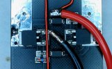
What I did was to isolate the pads at the 3-pin connector. I moved the wires to the bottom;

View attachment 2877
View attachment 2876
Note that I moved the cut of the trace between the two horizontal wires.

I should add a word of caution here: the stippled pattern trace under the black solder mask is un-terminated. If the wire insulation or the black epoxy insulation on the board are breached, you will energize the plane. Solid wire is very forgiving in robust structures. Please be aware of the limitations exploiting these properties. There are often very small blessings keeping you from misfortune. Due diligence is the watchword.

Time to make a new frame again :disgust:

View attachment 2878

Welcome to the forum @orten .


I do want to add here that this little Box Troll IH is a nice testing vehicle. Compared to the earlier full module, I am still sold on the HalfPint concept. I like the way it delivers and I like the way I can augment my experience with Sip&Dip [tm master piggy] to enhance the draw. A few seconds won't fry the bowl. I find the bake gentle on the terps while still delivering a righteous punch. More manageable heat in my most humble opinion.
What component did you use for the coil switch and is there a reason you stopped using it? I've been trying to find a post which references a contact-in-coil based switch design but cannot find one with the search function. I was contemplating rounding off the tips of some 2.00mm mag wire but reckon repeated use might abrade the Vapcap.
 
simulacra,

TommyDee

Vaporitor
Hello @simulacra - I am using the contacts that Flite is using. I changed the way I achieved the connections. Once the junction between the chokes are isolated from the gate resistors, the IH can be triggered with plus connected to the gate resistors through a pair of contacts.

See if this makes sense;
20200922_180001.jpg
I isolated the pads at 6:00 o-clock;

Then added these wires in order for a shunt with a VC to close the circuit;

20200926_115745.jpg
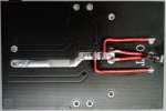
The leg on the right of the image is the center-tap of the coil sub-assembly;

20200926_112354.jpg
 
Last edited:

blastfromdapast

New Member
So, just to check ONE more time before I get the gear out, after I strip the caps and torroidal cores off the board, I am beefing up the trace between the MOSFET legs, cutting the large trace on the opposite side of board, configuring the single cap and inductor, and use the 18AWG to run thru the two holes by the three output holes, and solder the 'tap' to the coil winding and then run a hot and GND rail to power the unit and wire in my switches and indictor LED and put it in the box. Am I missing anything? Oh will the 5Amp 250VAC momentary still handle the current. I think that is it but I might be overlooking the obvious. Just a check and getting excited and feeling a lot better. This little project has been just the thing to give me a boost at this time with this illness to keep me positive and thanks to all who have helped.

Doug Baird
cheers everyone!
 
blastfromdapast,
Top Bottom