DIY Induction Heater Builds and References

TommyDee

Vaporitor
Technically yes. The most power you will get is 60 watts or there-about. You would tune the converter to only pull 60 watts. You would need a way to confirm the power draw, like a current meter.
 

BirdFisher

Member
But... I'm confused, I though 60W wasn't enough, isn't it what you said earlier about my two 5A & 6A bricks?
 
BirdFisher,

TommyDee

Vaporitor
Aha! There is the magic of a proper regulator. The ZVS is an analog device that will take an input from 5V to 12V. The more voltage you give it, the more current the device demands. So if you turn down the voltage, aka DC-DC buck converter, the IH will demand less current.

In order to know you are not exceeding the 5 amp supply limit, you need to manage the power level, total watts, to know you are operating in an appropriate range.

This is the reason to have enough power on hand for all foreseen requirements, but with a little creativity, you can overcome. Yet, heed my warnings. Get an amp meter, even a cheap one - https://www.ebay.com/itm/AMP-Meter-...et-Panel-Factory-New-85C1-Analog/283948981302 - and a volt meter of any kind so you can do the quick math of V*I=W Voltage times amps equals watts.
 

BirdFisher

Member
Aha! There is the magic of a proper regulator. The ZVS is an analog device that will take an input from 5V to 12V. The more voltage you give it, the more current the device demands. So if you turn down the voltage, aka DC-DC buck converter, the IH will demand less current.
Aahhh... And so what could have happened with my 5A and 6A bricks, is that they somehow under-powered the device, giving it 12V allright, but less current than this voltage implied... Right?

Ok, so just to be sure (sorry if I sound redundant, I really want to be sure not to fry more modules) Is the big 12V 8A Salcar brick in the photo above safe?
 
BirdFisher,

TommyDee

Vaporitor
Redundancy just makes things clearer so I appreciate it.

The 12V 8A brick is the safe bet without any other elements like regulators. The IH module will not pull more current than that. And that is the key, it is not what the power supply will put out but what the device you are powering demands of the power supply.

As to the assessment, close. The power brick is trying to put out 12V but cannot quite get there. So the brick puts out all the voltage it can which is balanced by the required current of the device. The current and voltage kind of balance out to maximize the output it can achieve. With a 60 watt supply, the voltage might be as low as 9V pushing more amps than it was designed for which creates internal heat which stresses the power brick. Power bricks usually die slowly if they are over taxed.

I am not a fan of oversized power bricks. Battery packs are much more efficient in space in my opinion. I make use of old laptop supplies with the DC-DC converter. They are normally of higher quality and have more than enough power at around 70 watts. And they are quite a bit smaller than the generic offering. I find the standard ZVS module does a very thorough bake at around 10-10.5 volts.
 

BirdFisher

Member
Thank you very much for your patience, I understand now.

I am not a fan of oversized power bricks. Battery packs are much more efficient in space in my opinion. I make use of old laptop supplies with the DC-DC converter. They are normally of higher quality and have more than enough power at around 70 watts. And they are quite a bit smaller than the generic offering. I find the standard ZVS module does a very thorough bake at around 10-10.5 volts.
Ah, but I'd - seriously - love to build a battery-powered device, but I never found a guide that I could follow, with a parts list, a wiring diagram, possible charger models... That would really be tops, do you know of any?

EDIT - I just found this, so I'm getting closer :rockon: First, get those parts.
 
Last edited:
BirdFisher,

TommyDee

Vaporitor
:tup: I hear you. I have one snag and one advantage in reply. I only trust digital or well regulated supplies for chargers. I've always treated my li-ions with respect for flashlights. For me, 12.6V/8.4V has to be the top of the charger and anything less is loosing runtime.

BMS is pretty simple and they are a little annoying. There are two styles that are 10A. You want 10 amp so it doubles as a fuse. If you touch them, they go into a locked mode until you hit it with a charger. That is the annoying part. Plan on charging with the batteries in place or you will get highly annoyed with having to reset the BMS every time you replace the batteries -or- make sure you cannot touch the BMS bits by putting it in shrink wrap or something.

20200911_012849.jpg


My advantage - access to 3D printers.

What is different about this pack and the black plastic standard issue is my pack has opposing polarities. The standard black housings have + embossed with all the cells facing in one direction. Basically, plan out the wiring so it makes sense in your design. Know that the two style BMS board have different tab-layouts. If you plan on something as integrated as I did here, these little differences matter a lot. They are opportunities to exploit.

=================================================

Box Troll Update;

This is the 3rd rendition of "Box Troll" featuring a new slimmer frame and a DynaMag.


20201005_144226.jpg

The DynaMag is worth $5 if you're ordering anyway. It is only 1/16" thick. To make the magnet strong in the 3D print, and to increase the cooling effects, I put the N42 Diamagnetic 1/8" thick magnet underneath. The depth in the print is 4.5mm to leave the DynaMag just a hair proud of the 3D print and the edge of the box. That let me loose the N52 'decapper' magnet.

I missed the button actuator on the battery meter by about a 1/2mm. There are some tape dots on the switch button to solve that issue with the 3D design. Works a charm to not have to reach into the box to see the meter lights. They display nicely in the bay.

20201005_144359.jpg

I did say I simplified things. You know it always means I made things very complex to make them simple, right? Look for what's missing.

20201005_144444.jpg

20201005_144508.jpg

"Did TommyDee -actually- put in a coil-activated switch?" Sort of. Still want to clean that up a little but yes, no manual switch.
 
Last edited:

gostavs

Well-Known Member
Accessory Maker
Thank you so much tommydee for everything you put out! These experiments/builds/guides/tips&tricks are very appreciated! I am designing a 3D printed case for a 3S 18650 portable IH and want to use your latest thin HalfPint mod. A few questions if you don’t mind :)
In your latest post you teased us with a coil activated switch, can you explain how it works? Would that still work if the coil/glass is pointing “forward” in your boxtroll instead of how you have it now, pointing upwards?
How is your coil wrapped, how many turns and is it two layers of coil or am I seeing it wrong?
Also, do you know what to avoid/look for when buying ZVS modules? I’m buying from AliExpress/China.
 
Just to complete my saga. This is the end of my half-pint wired project... don't ask me... I literally soldered some stuff while the box was closed. Tiny. Nice to hold while drawing. The tubing light (led on the bottom inserted in an silicone plug) gives help to know what's going on while this thing is in your face. So next challenge : HalfPint plus 1000mA LiPo-pack


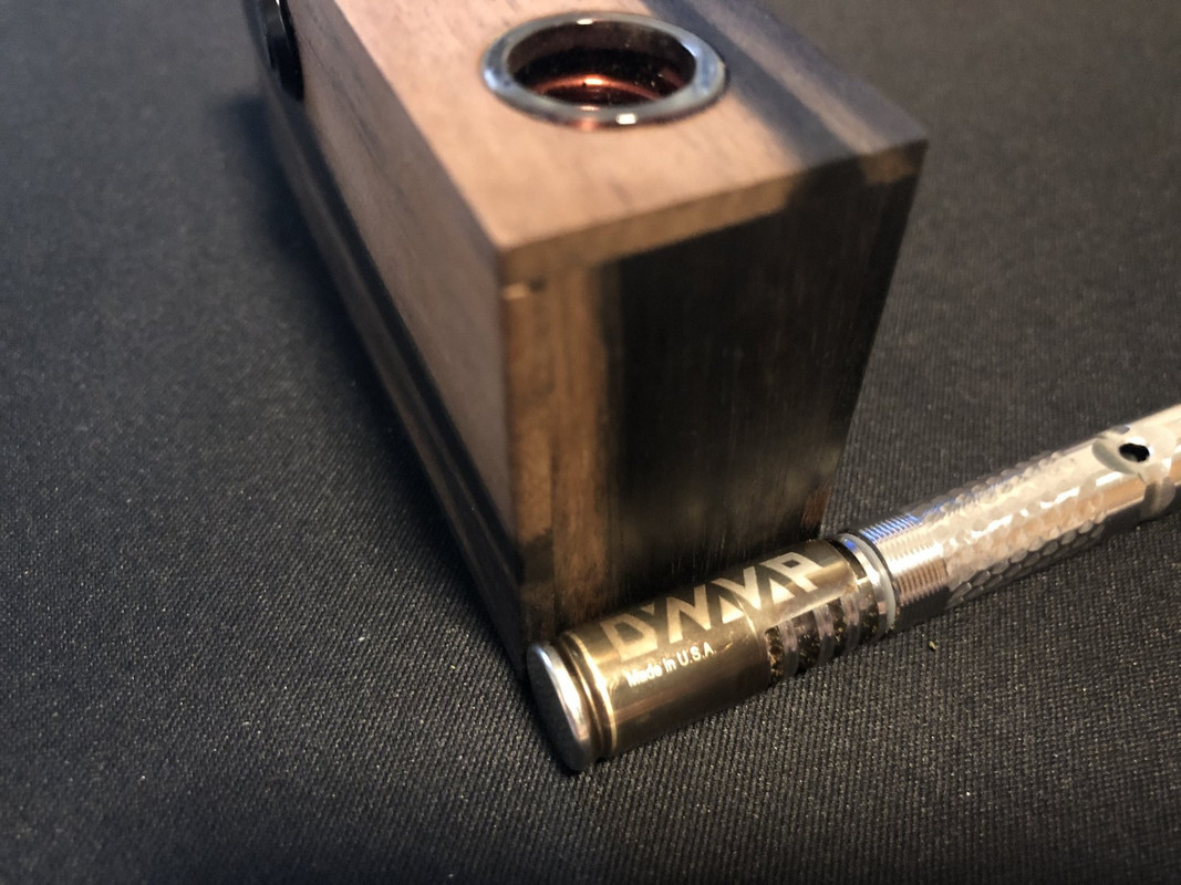
Witchcraft I tell you... WITCHCRAFT...!!!
Good day... :-)
 

TommyDee

Vaporitor
Thank you so much tommydee for everything you put out! These experiments/builds/guides/tips&tricks are very appreciated! I am designing a 3D printed case for a 3S 18650 portable IH and want to use your latest thin HalfPint mod. A few questions if you don’t mind :)
In your latest post you teased us with a coil activated switch, can you explain how it works? Would that still work if the coil/glass is pointing “forward” in your boxtroll instead of how you have it now, pointing upwards?
How is your coil wrapped, how many turns and is it two layers of coil or am I seeing it wrong?
Also, do you know what to avoid/look for when buying ZVS modules? I’m buying from AliExpress/China.
Thank you for the questions. First of all, a discussion about 'switches' led to an idea I saw a long time ago and IIRC, it was deemed an excessive heat sink. I took the idea a little further and added compliance. An 'open switch' using the VC as a shunt. Little battery contact from old phones is a good way to get there. I had some contacts from an old build I could use. Be aware this may scratch colored caps. Not sure but don't want to forget to put that out there.

For alternate orientations, you have to add the right geometry to get a shunt to work. There is nothing wrong with setting up a remote 'shunt' switch from the ZVS. What you see in the images above is me liberating 2 pads to make the junction for the switch/shunt convenient.

I strive to maintain original wire length of the work coil. A favorite tip is to simply move coils out of the way in DIY builds if you want 'less heat'. I opted to simply continue wrapping. The original length is 28-30 inches of 12 gauge [2mm] magnet wire. I opt of a 20mm long x 16mm ID for my primary heating zone. I continue the wraps on the outside loosely, normally getting about 3 turns on the outside. This ensures the circuit remains somewhat balanced and the circuit parameters remain predictable. Box Troll has an 8-turn 15mm ID coil with 5 wraps on the outside. I have the room the upgrade that at a later date.

I have received all manner of ZVS modules but I've overcome most. Some rare advantages can be exploited. Alas, we are given what we are given. The instructions cover the most common features available to all. A rare breed is the full ground plane version.

Of the ZVS board I receive, I pull them all apart first thing. I check the solder joints and clean the holes. Make sure the diodes are facing the right way and that the resistors '471' are properly soldered. When I re-assemble capacitors and inductors, I make sure I get a solder bead on both sides of the board. My instructions above show how to minimize losses.
 
Last edited:

TommyDee

Vaporitor
Today is a good day. I decided to try the heat-separation method of shortening one of my 1" tubes to 20mm - the limit for Box Troll. Didn't work for me but I might have cheated. I have some cheap Chinese diamond cutoff wheels and decided to use that as the scratch medium. With the tube in the lathe, the score was pretty simple but it wasn't about to act like a stress riser. So I had to keep cutting with the disk hand-held like a file. Some torment later, enough glass was ground to dust for the ringlet to go flying.

I brought out the torch setup to polish up the ugly cut and she turned out nice and clean. The other side has a nice hard/clean edge which will be the grade A side.

Got the length of the glass tube at 20mm on the money. Now to make the perfect coil for Box Troll.
 

gostavs

Well-Known Member
Accessory Maker
3D printer and a spindle to the rescue.
Would it be possible to get a coil jig .stl for coil winding from you? Is it something similiar to this: https://www.thingiverse.com/thing:4545014

I have a module that I shorted on the positve/negative input, is it the fets that are the first to go? I know I read in an earlier post of yours what values to look for with a multimeter but I cant find it now, care to repeat that?
 
gostavs,

TommyDee

Vaporitor
The thingiverse jig is about what I modeled.

FETs short when they fail. Measure ohms across Negative and the Work Coil pad with the coil in place. Forward biased, I read open, and reverse biased I read approximately 5K.
 
Well removing one inductor and one cap works great. I did 5 back to back tests with this configuration no problems. Saves space and saves buying a MOSFET switch.
can someone link me to a wiring diagram on how to achieve this please!

Ignore me i kept reading
 
Last edited:
ImLosTheGhost,
  • Like
Reactions: TommyDee

goodpunk6

Well-Known Member
Just to complete my saga. This is the end of my half-pint wired project... don't ask me... I literally soldered some stuff while the box was closed. Tiny. Nice to hold while drawing. The tubing light (led on the bottom inserted in an silicone plug) gives help to know what's going on while this thing is in your face. So next challenge : HalfPint plus 1000mA LiPo-pack


I will buy this from you
 
goodpunk6,

AWistfulNihilist

Well-Known Member
I saw this just a bit ago. I thought it was a cool idea and if the idea was fine tuned I could see it going somewhere.
https://www.reddit.com/r/vaporents/comments/ka9rkh
I'm here too brother!


Appreciate the shout out
 

iDRINKBLEACH

knowing is half the power - Gi-JOE
Accessory Maker
I'm here too brother!


Appreciate the shout out
Haha heck yeah. No problem I like the idea behind it.
 
iDRINKBLEACH,

TommyDee

Vaporitor
You could make the head quite a bit smaller if you wanted.

I love the concepts but the size is problematic. There is an opportunity to put only the coil and the black capacitor near the bowl. The connecting leads need to be sizable, and they need to run nearly parallel and close together, but they can be be conventional 12 gauge wire pair. The circuit board and inductors can remain remote. Limit the lead-length, of course. The lead-wires are still part of the active inductive circuit. That is why the lead-wire pair needs to run close together. Look at silicone hobby wire for flexibility.

Theory behind this - the work of the IH is done with a signal bouncing back and forth between the capacitor and the work coil. That is where all the high current happens. The feed-circuit, the energy stored in the inductors, is buffered by the inductors themselves stretching out the time domain. The capacitor's discharge is nearly instantaneous and is the reason for the high current pulse directly into a 1uh inductor, a virtual short circuit. Pay attention and you can fashion a nice little heater-head with a remote circuit box.
 

iDRINKBLEACH

knowing is half the power - Gi-JOE
Accessory Maker
You could make the head quite a bit smaller if you wanted.

I love the concepts but the size is problematic. There is an opportunity to put only the coil and the black capacitor near the bowl. The connecting leads need to be sizable, and they need to run nearly parallel and close together, but they can be be conventional 12 gauge wire pair. The circuit board and inductors can remain remote. Limit the lead-length, of course. The lead-wires are still part of the active inductive circuit. That is why the lead-wire pair needs to run close together. Look at silicone hobby wire for flexibility.

Theory behind this - the work of the IH is done with a signal bouncing back and forth between the capacitor and the work coil. That is where all the high current happens. The feed-circuit, the energy stored in the inductors, is buffered by the inductors themselves stretching out the time domain. The capacitor's discharge is nearly instantaneous and is the reason for the high current pulse directly into a 1uh inductor, a virtual short circuit. Pay attention and you can fashion a nice little heater-head with a remote circuit box.
Bill Hader Reaction GIF

I'm ready for science.
 
Top Bottom