DIY Induction Heater Builds and References

TommyDee

Vaporitor
Thanks for reporting back on that test @Edgedamage - I know the specs on the cutoff voltage is very cavalier.

The 14500 were weak enough that even as a matched pack, they'd have trouble without a balancing circuit between the cells. They were rated for for it but failed under scrutiny.

If you do cells, you can do protected cells. I have 10A (8.5 amps) 18650. That way you know each cell is protected, although still considered second level protection. Nothing beats a good old fuse soldered in the line in my book.

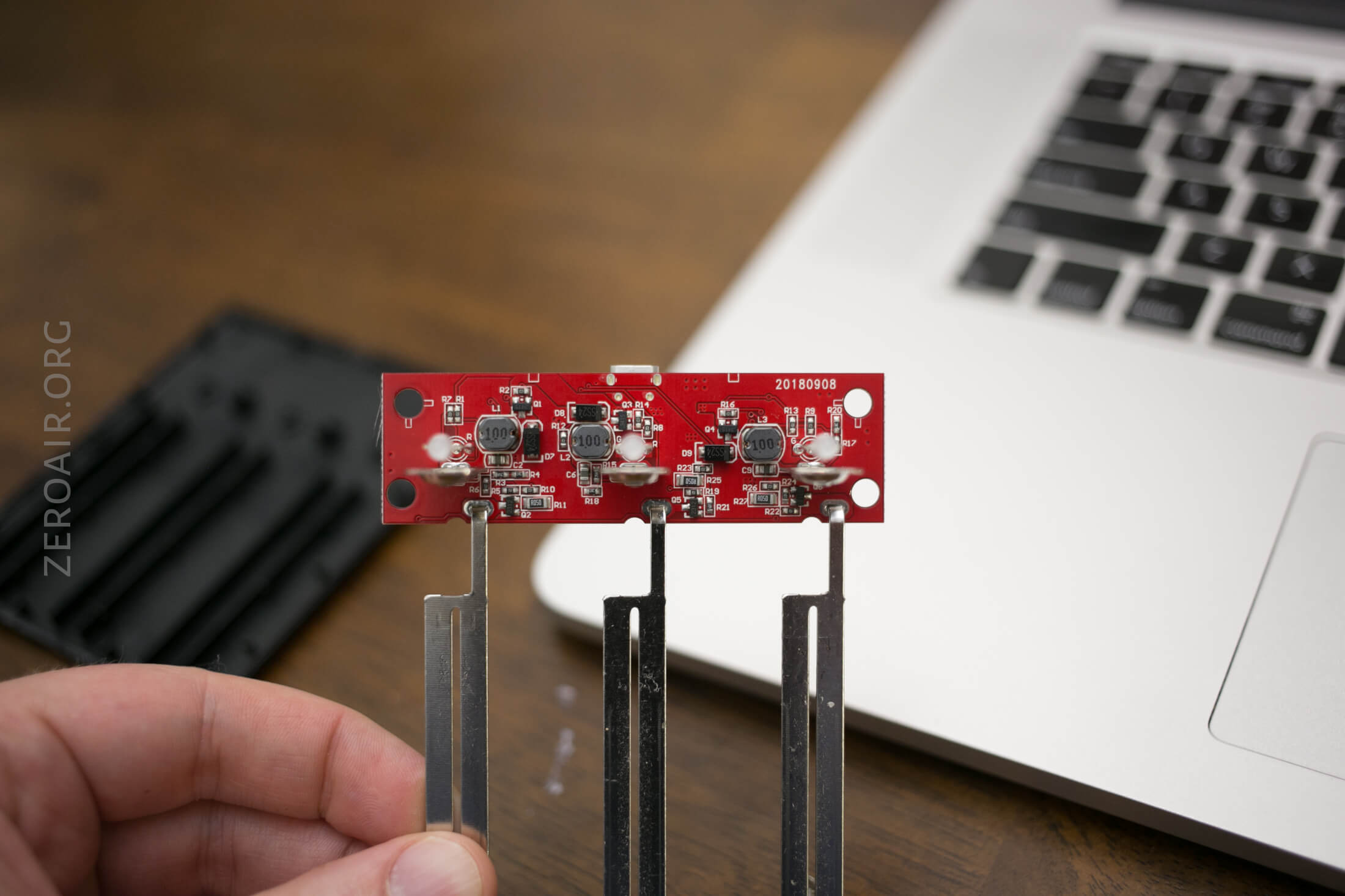
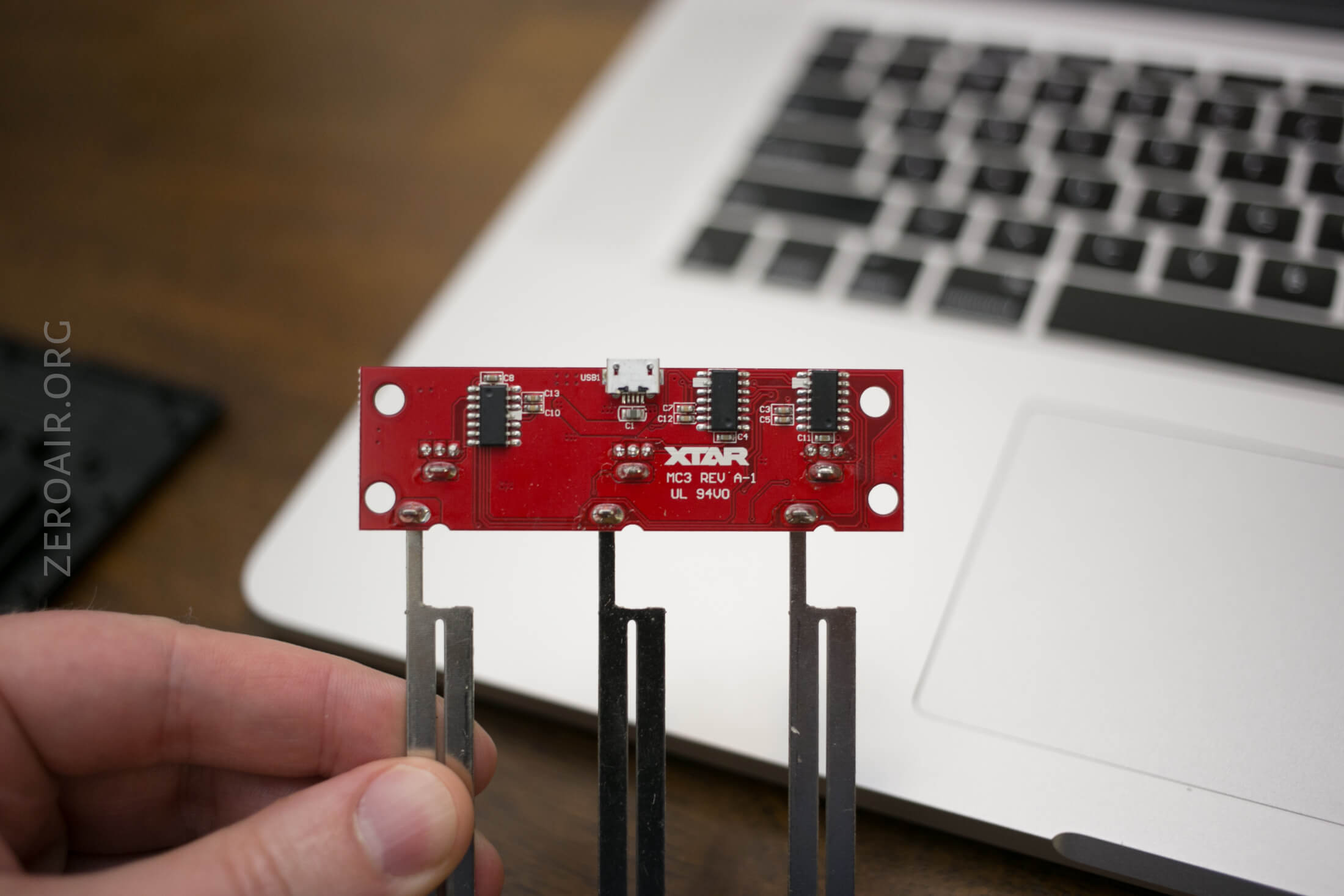
What do you think of the 2S/3S chargers?
 
TommyDee,

Edgedamage

Well-Known Member
To be honest I only trust Nitecore and the likes for single cell charging. And hobby grade chargers for 2s to 6s charging using the balance leads. I have messed with 18650's for 6 years now, and still don't fully trust them. Oh and the 2s and 3s chargers that are the wall wart type don't really like them.
 
Edgedamage,

TommyDee

Vaporitor
Yep, seen that video. That is why my DIY charging regime is still open.
I could see 3 isolated XTAR M0's doing the best job. Those are great little modules.
I'm waiting to evaluate a DC 2S/3S charger. Mostly for the regulation up front. That is one thing missing in the Chinese BMS.
 
TommyDee,

Edgedamage

Well-Known Member
For now I will use my cheap BMS for short circut protection, and use a 4 bay charger for the cells. And future battery builds which only I will use. Will have no BMS just a main power switch and a fuse with a voltage display.
 
Edgedamage,

TommyDee

Vaporitor
I really want to get away from removing the cells daily [18350]. I can easily bring out all 4 tap leads to a balance plug. Still not sold on a mains disconnect but the fuse - definitely. Also like the protected 18650's. 3500mah flashlight safe with a realistic working current of up to 8.5 amps continuous [labeled 10 amps]. They just don't fit common carriers, but they're safe as hell. I want that protection put on 18350 IMR 10 amps cells. I can make cell holders any length I want.

Once I have a robust 3S balance tap, I can wire it to a certified charger, either on-board or plug-in remote.
How about re-purposing this cute little XTAR to make for a USB charger... I like this as a $20 safety gizmo - XTAR MC3

ff204b84-9fcb-4801-825f-7ac5c6d73a78.jpg


remove the cradle and you got a slim little "dock".

Okay, so I admit that will take some wiring acrobatics so the mains switch may be useful for this arrangement.

I did find these from the MC3 -

zeroair_reviews_xtar_mc3_3-bay_charger_15.jpg
zeroair_reviews_xtar_mc3_3-bay_charger_16.jpg


11.86V is where I loose the 3rd grn light. 11.3V I loose the second grn light while firing.
At this rate we're going to be in the red quickly. They may be aiming to keep performance up by charging a lot. If you have a volt meter, plug it into the charge port. Always active; which is scary because it is not very shallow. I don't want to find out how to reset the BMS.
 
Last edited:
TommyDee,

Edgedamage

Well-Known Member
One idea with your 3d printer you can make a cell holder with a integrated Dean's connector or xt60 connector. That slides on and off your IH, and charger stand. As for fuses I was thinking of the ones that unregulated box mod builders use. 15amp polyfuses that self reset.
 
Edgedamage,

TommyDee

Vaporitor
I really like the idea of a quick change pack like cordless drills and things. That has to be considered in the industrial design of the project. I can think of a quick plug-in pack even within the product but that doesn't solve charging 3 cells at once. That is the part that I want foolproof, exactly as you decided with the BMS solutions.

If I can get to the USB Micro for charging, even at a 1/2 amp, I'd be in heaven. The MC3 is a very nice little battery charger but it may require 3x MC1's with a USB Micro boost converter in order to series the chargers. I might have to rip into some of these power tool chargers to see what's going on in there.
 
TommyDee,

Edgedamage

Well-Known Member
I have followed DIY powerwall and battery pack builders on youtube, and noticed they and Tesla use thin wire for fuses. The legs of small resistors are perfect and they only take 6A to blow. So taking my 20A cells I did some tests and yup works like pack builders say. I made a test rig with a 10A car horn button, and a DIY fuse holder and when the button is pressed instant pop.
P-20200707-170402.jpg

P-20200707-170425.jpg
P-20200707-170514.jpg
P-20200707-170720.jpg

So future builds will have a fuse in them, using this method. I will connect it to the negative connection on the IH module.
 

TommyDee

Vaporitor
Yep, exactly. 1/4 watts resistor lead-wires? Today Tesla etches the fuse shape in their joiner-sheets but yes, way cool technique for cutting out bad cells. Caveat; don't have anything nearby that can burn. Car fuses are so small today that they wire in nicely. If they blow, something else fucked up that needs investigating.
 
TommyDee,

Edgedamage

Well-Known Member
Yep, exactly. 1/4 watts resistor lead-wires? Today Tesla etches the fuse shape in their joiner-sheets but yes, way cool technique for cutting out bad cells. Caveat; don't have anything nearby that can burn. Car fuses are so small today that they wire in nicely. If they blow, something else fucked up that needs investigating.
The slow burn you see in the video, is a tiny flash in my tests. But yes keeping naked fuse wire in a build has a risk if anything can burn.
 
Edgedamage,

TommyDee

Vaporitor
Love those VEeWEe conversions! I remember a lead acid conversion from almost 30 years ago. Converter and an adapter plate LOL Doubled the Bug's output.

I thought I have a few of these around...

MT3608-DC-DC-Adjustable-Boost-Module-2A-Boost-Plate-Step-Up-Module-with-MICRO-USB-2V.jpg


There's my source voltage for USB conversion.
 
Last edited:
TommyDee,

Ganja gun

New Member
The system reduces output by about 5-8 watts at comparable voltages and therefore less current draw. Technically, you've reduced a 120W heater to 60 watts. I run it up to 80 because the FETs are rated for 120 watts and nothing gets remotely warm except the main VC coil. And at the right wire gauge and turns, it just barely gets warm.

The biggest difference comes from coil configurations. Count on a hotter IH at under 30 inches of 12 gauge wire, which is the stock coil as close as I can tell, to be hotter, require more current. Longer means less current. Sample - stock 65 watts at 10 turns; a coil was 60 watts with 11 turns and 70 watts with 9 turns. I am enjoying the 9 turn coil at this moment. They are the stock diameter. All else being equal so to speak.

...

And if you have this kind of board, I don't like the negative feed wire. I wire directly to this wiggly trace between the two source pins -

View attachment 1305

There is not much via feeding these leads. I don't like needless losses in traces. Some board with full ground planes don't suffer this issue. The copper grid on this board is not terminated that I could tell. Or else it would be terminated here.

...

And the switch bridging whatever trace connects that positive-out pad to the long trace. This enables LED's and the voltage to the gate pins on the FETs.

View attachment 1306
Max temperature ?
 
Ganja gun,

TommyDee

Vaporitor
Max temperature ?
Temp of the VapCap is "normal temps" but the circuit itself should remain 'touchable' throughout and after a normal heating cycle. FETs remain cool, the capacitor and inductor remains cool, and the work coil and its lead wires tend to get warm. Nothing that has ever burned me. I have put 4 different units in 3D printed plastic housings and so far, no deformation. Sidewalks in Texas get a lot hotter.
 
TommyDee,

BabyFacedFinster

Anything worth doing, is worth overdoing.
Just wondering. Instead of using a longer cord to increase the time to click on my Caldron. Could I use a variac on the IH to decrease the power? I have an old variac lying around here.
 
BabyFacedFinster,

TommyDee

Vaporitor
Can you make it full wave DC? Maybe a filter cap? Pushing 9-12 volts? Why yes you could with that. It does require DC that maintains 2.3V minimum to keep the gate energized.

I'd say power it with 2S 18650 and see what you get. That will be a slow heater.

@Edgedamage - what is the blue staking stuff you're using to hold shit down? Runny hot glue or something more reliable?

P-20200707-195356.jpg
 
Last edited:

BabyFacedFinster

Anything worth doing, is worth overdoing.
Can you make it full wave DC? Maybe a filter cap? Pushing 9-12 volts? Why yes you could with that. It does require DC that maintains 2.3V minimum to keep the gate energized.

Would it be an issue to just plug the Caldron's power supply into the variac?
 
BabyFacedFinster,
Top Bottom