DIY Induction Heater Builds and References

phattpiggie

Well-Known Member
Accessory Maker
@RedEyeFlightControl I'm an ex electrician who can solder and used to build custom motorcycle looms but unfortunately electtronics and myself don't get on.
The majority of the conversation here goes over my head. I think I switched off at school with 'and' and 'nand'.
There have been a few triple IH conversations going on but it won't be me sorts one out. I don't have the time either these days.

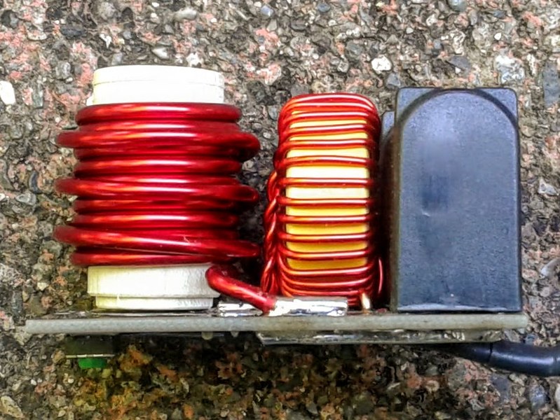
It's great to see how small the Trace boards can end up.
The only issue with them is the shape, a proper pain in the backside to build wooden enclosures around.
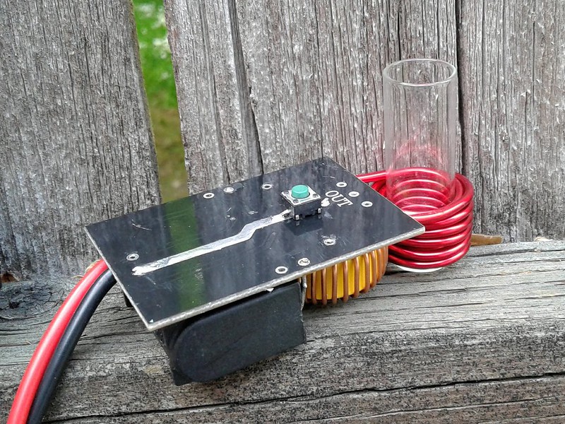
My first one from @Pipes came in this configuration, was hoping to go down the 'log' path. It's been stripped and rebuilt a few times.
dav.jpg


@TommyDee they work fine, I'd say mine runs a little under an amp, it takes a little longer than the 12.6v 1a warts.
If you're going to fit one of the USB style ones to a BMS fit a diode, I had one take a 12v down to 7v.
IMG-20200708-163839.jpg

IMG-20200618-WA0002.jpg


I've seen a few videos on BMS, I'd be happy to use them. The OG Mini is still running and the battery seems fine and it's been used every day for a long time now, over a year easily.
Again my electronics knowledge is poor so I take onboard the views of the more experienced.

Just because I haven't the ability to build them doesn't mean I don't take any notice of what's on the market and I've had a couple of prototypes come my way.

For me I don't see the point in spending money on another version of the Trace heaters they will all be much of a muchness.
I had some contact with a guy on IG about the Alpine heater, it's a modified Trace heater.
Pre release pictures.
Screenshot-20200709-103404.jpg

Screenshot-20200709-103345.jpg


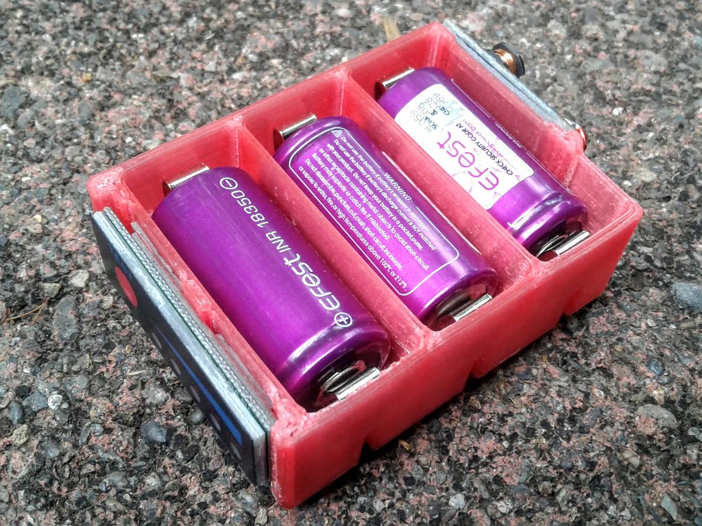
This is the BMS in the Mini
 
Last edited:

TommyDee

Vaporitor
@phattpiggie - Would something like this with the coil facing left be more workable for a log?


50094264658_a4e93445c2_c.jpg


Same with this arrangement; turn the coil to face 'outward' for a log.

50095074472_7e7f520ec8_c.jpg
50094837651_55c13e599d_c.jpg
edit; this has a 40.5mm max x-section

These can do 80 watts and barely break a sweat even with half the circuit.

Thanks for the tip on the diode. Utilizing the USB input just makes so much sense when you have an onboard power supply. I'll have to see how it performs on my packs. Just now getting to them.

Damn, can't paste images from the NFC!

-----------------------------------------------------

And in todays "neighbor postal mail exchange..."

... a pair of these walk over :cool:

s-l1600.jpg

30v80amp mosfets w/ discrete charge circuits.
Anyone figure out what S1 and S2 are? I'm assuming charge and done indicators.
 
Last edited:
TommyDee,

TommyDee

Vaporitor
I made quick work of my new acquisitions.
Built a fully sustained 10 amp 18350 3S pack.

Is this SteamPunk or what :brow:

20200711_182916.jpg

Of all things, it outside dimensions end up being 72x48x24 mm - No shit!

And a meter of course;

50102667911_039cc56aca_b.jpg


I charged the cells as a pack from 11.1V to 12.40V The USB converter drew a hard 1A but dropped to 3V. This is not great news as that means the 10W converter was working at 3 watts. Stayed nice and cool. Charge took about 3-1/2 hours. If I have a current-limited USB supply [rated]. then this works great. As a 10W converter, it could fry. So I need to see what the implications are.

I like the circuit. I have simple taps for wires and it is wired to deliver 10 amps with only battery contact losses. All the wiring is solid 15awg magnet wire except the charge wires, which are 18 awg.

I will build this into a FlatPack configuration. It took me some time to wrap my head around how I wanted to wire this particular BMS. I decided to upgrade the 3D printed case to accommodate the extra bits. The cells still push out from behind and the clear bold polarity markings are preserved on the farside of the BMS. Good 'ol auto trim tape, a foam rubber formulation, made quick work of mounting the meter and the USB converter. The BMS is held in place with double sides cellophane tape. All the hard-wiring will be sure to keep the BMS in place.

A note on the BMS - it comes with silver pads. They aren't wetted and they reject solder at first. I removed them as I found no use for them. Lesser of two evils - preserve the board.
 
Last edited:

RedEyeFlightControl

Inventor,Maker, Pro Nerd, Entgineer, GladScientist
Manufacturer
I made quick work of my new acquisitions.
Built a fully sustained 10 amp 18350 3S pack.

Is this SteamPunk or what :brow:

20200711_182916.jpg

Of all things, it outside dimensions end up being 72x48x24 mm - No shit!

And a meter of course;

50102667911_039cc56aca_b.jpg


I charged the cells as a pack from 11.1V to 12.40V The USB converter drew a hard 1A but dropped to 3V. This is not great news as that means the 10W converter was working at 3 watts. Stayed nice and cool. Charge took about 3-1/2 hours. If I have a current-limited USB supply [rated]. then this works great. As a 10W converter, it could fry. So I need to see what the implications are.

I like the circuit. I have simple taps for wires and it is wired to deliver 10 amps with only battery contact losses. All the wiring is solid 15awg magnet wire except the charge wires, which are 18 awg.

I will build this into a FlatPack configuration. It took me some time to wrap my head around how I wanted to wire this particular BMS. I decided to upgrade the 3D printed case to accommodate the extra bits. The cells still push out from behind and the clear bold polarity markings are preserved on the farside of the BMS. Good 'ol auto trim tape, a foam rubber formulation, made quick work of mounting the meter and the USB converter. The BMS is held in place with double sides cellophane tape. All the hard-wiring will be sure to keep the BMS in place.

A note on the BMS - it comes with silver pads. They aren't wetted and they reject solder at first. I removed them as I found no use for them. Lesser of two evils - preserve the board.

I love it. It's crisp, clean, and to the point. No funny business. A+ In my book!
 

badbee

Well-Known Member
Hey @TommyDee or @RedEyeFlightControl have you tried measuring temp with a thermistor? I've been experimenting and even heating the IH with a torch and directly applying a tiny 1.3 mm thermistor to the cap I only pick up a temp of about 120 C. I've tried applying it to different parts of the cap side and bottom with and without pressure. Other sensors from my multi-meter and an oven thermometer give similar results. The temp measured externally is highly variable (120 C was the max of many attempts) and can't be level scaled to predict the click temp. The thermistors themselves are very sensitive and react as expected to breath and the touch of a finger or hot cup of tea.

I guess it has something to do with poor thermal conductivity between the cap and sensor. Has anyone seen meaningful measurement with a thermistor?

P.S. One thing learned is that self heating of the sensor is a problem if it is oriented parallel to the axis of the coil but not so much if inserted perpendicularly between coil wraps.
 

RustyOldNail

SEARCH for the treasure...
Hey @TommyDee or @RedEyeFlightControl have you tried measuring temp with a thermistor? I've been experimenting and even heating the IH with a torch and directly applying a tiny 1.3 mm thermistor to the cap I only pick up a temp of about 120 C. I've tried applying it to different parts of the cap side and bottom with and without pressure. Other sensors from my multi-meter and an oven thermometer give similar results. The temp measured externally is highly variable (120 C was the max of many attempts) and can't be level scaled to predict the click temp. The thermistors themselves are very sensitive and react as expected to breath and the touch of a finger or hot cup of tea.

I guess it has something to do with poor thermal conductivity between the cap and sensor. Has anyone seen meaningful measurement with a thermistor?

P.S. One thing learned is that self heating of the sensor is a problem if it is oriented parallel to the axis of the coil but not so much if inserted perpendicularly between coil wraps.

Your assumption is correct, the small bead type thermistor needs to be mated to the material for accuracy, in this case somehow directly soldered to the cap. I’ve done this with measuring solder iron tips, and learned from the experts, that I needed to make a small “solder bridge”, with a bit of solder right to the thermistor’s tip, then I had accurate temps. I’ve also done this by running the thermistor wire up through a DV stem, and wedging the tip inside one of the cutouts on the DV’s metal screen. Here’s a photo, unfortunately doesn’t show the tip.

 
RustyOldNail,
  • Like
Reactions: badbee

TommyDee

Vaporitor
Putting the thermister into the load is about the only meaningful data. The cap is like capturing the remnant of an event that happened ages ago. The delay in response and the variability in response makes it a reference at best.

IR is the way to go for cap temp, but how the IH treats the metal is still important. Proper heat soaking is still a maker's game. I think Jeff's got some insight but he's not talking. @RedEyeFlightControl has some too but that's not really needed at the control level. Tune level maybe.

@NexVision - meters on order. Those are a bugger to find on eBay. Buy through Canada for much better rates; https://www.ebay.ca/itm/3-7V-2S-4S-...wer-Tester-Battery-Indicator-NEw/324012515133
 
Last edited:
TommyDee,
  • Like
Reactions: badbee

badbee

Well-Known Member
I’ve also done this by running the thermistor wire up through a DV stem, and wedging the tip inside one of the cutouts on the DV’s metal screen. Here’s a photo, unfortunately doesn’t show the tip.


Thanks RustyOldNail, I was going to try this next just to see what happens. Not particularly useful for the real world, but still interesting...
 
badbee,

badbee

Well-Known Member
Putting the thermister into the load is about the only meaningful data. The cap is like capturing the remnant of an event that happened ages ago. The delay in response and the variability in response makes it a reference at best.

IR is the way to go for cap temp, but how the IH treats the metal is still important. Proper heat soaking is still a maker's game. I think Jeff's got some insight but he's not talking. @RedEyeFlightControl has some too but that's not really needed at the control level. Tune level maybe.

@NexVision - meters on order. Those are a bugger to find on eBay. Buy through Canada for much better rates; https://www.ebay.ca/itm/3-7V-2S-4S-...wer-Tester-Battery-Indicator-NEw/324012515133

Thanks TommyDee, I'm not particularly surprised but a little disappointed. I didn't expect to measure the full temp but was hoping for something consistent that could be scaled. The problem is tiny differences in contact angle and pressure (I assume) lead to huge differences in measured value. Not only can't it be acted on, it's not even worth displaying for amusement.

I haven't seen that anyone has had much luck with IR either. Any suggestions for an IR unit that might work best (and isn't 0.25 surface mount)?
 
badbee,
  • Like
Reactions: TommyDee

RustyOldNail

SEARCH for the treasure...
Thanks RustyOldNail, I was going to try this next just to see what happens. Not particularly useful for the real world, but still interesting...

Well, as TommyD mentioned above your post, positing the bead tip sensor where the load is, probably the closet we can get to monitoring a DV’s temperature. Further down the page I linked to had the results of my tests, which were geared toward where placement of the DV in the IH insert correlated to temperatures. So I didn’t need any load in the DV.

However, I’ll disagree about using IR temperature readers, for being useful at all in most vaping gear tests. While there maybe models out there, that can read very TINY areas on objects, I’ve never seen one, and it would probably be lab type expensive. I own a Fluke 62 Max+, a decent handheld IR thermometer. But none of these can get close enough with their wider field of view, to read tiny objects, then you get into the world of “emissivity”, and how objects reflect heat. I see people list temperatures all the time using these meters, sorry, in most cases it’s the wrong tool, and therefore results are inaccurate. They do have their place, unfortunately not in my vape world.
 
RustyOldNail,
  • Like
Reactions: TommyDee

TommyDee

Vaporitor
IR light can be focused. Consider a sphere for focusing the light. Has to be the right material I think.

@badbee - the rate of heatup with changes the rate and final temperature at the flat face of the tip is a result of direct heating and indirect heating. Using a PID system, you can control getting to a specific temperature quickly. It is an algorithm that maximizes heatup without overshoot. And it can sustain it. If you slow the rate of heating, the chamber and the tip will be more consistent with each other. It will even make up for on-demand heat although it experiences a lot of hysteresis. Training a system would target the exact chamber temps based on machine learning. Because this system is configuration based, there should be a library for all the different tips. With this little bit of effort, you can dial temps within 5-10*C in any vapcap. It is still interpolation, but this can be calculated at insane speeds with some optimization in the characterization process. The library manages variation to make it user selectable or give the user control. Give the user training mode and really watch thing go wild.
 
TommyDee,

TommyDee

Vaporitor
Refraction.jpg


We need to concentrate the 'image'. Remember that the IR thermometers use a Fresnel lens to focus the 'image' onto the sensor.
 
TommyDee,

RustyOldNail

SEARCH for the treasure...
Refraction.jpg


We need to concentrate the 'image'. Remember that the IR thermometers use a Fresnel lens to focus the 'image' onto the sensor.

I understand the theory, but where is the meter one can buy affordably, that can accurately measure a 10mm VapCap?
D6-BE5-D72-38-B2-439-E-9-A0-E-EC3411-F52-FB9.jpg
 
Last edited:
RustyOldNail,

TommyDee

Vaporitor
oh sorry, there are development kits listed a few pages back...


It's actually a sparkfun device but I know Digikey has them available. This same or similar sensor can be ripped out of an IR thermometer. They're back down to a reasonable price again.

The PID temperature control is something @RedEyeFlightControl can explain a lot better than me. It is a fairly sophisticated algorithm that uses predictive modeling to achieve a goal. All doable in Arduino. The kit should have support for that. And yes, that is an Atmel 328 chip already wired in.
 
Last edited:
TommyDee,

TommyDee

Vaporitor
I think this is what @RedEyeFlightControl is up to. The basic thermometers can be tuned for the cap, but the lens needs to be changed. I am not sure if the photo-black tube behind the plastic lens is metal or not. However, the spherical lens conversion would cover the refocusing of the device; Problem; you cannot tap into the data lines. You have read-back, sure, but you can't feed that back into your own controller. If you could, you could reprogram the screen too. It is a canned system that is useless except maybe the sensor itself. And the price for core sensors will come back down again as high temp sensors are not C'19 compatible. This world of IR sensing is a world of smoke and mirrors but it can do some awesome things with vape. It is very much akin to temp control on coils. Just a different read-back device.
 
TommyDee,

RustyOldNail

SEARCH for the treasure...
I think this is what @RedEyeFlightControl is up to. The basic thermometers can be tuned for the cap, but the lens needs to be changed. I am not sure if the photo-black tube behind the plastic lens is metal or not. However, the spherical lens conversion would cover the refocusing of the device; Problem; you cannot tap into the data lines. You have read-back, sure, but you can't feed that back into your own controller. If you could, you could reprogram the screen too. It is a canned system that is useless except maybe the sensor itself. And the price for core sensors will come back down again as high temp sensors are not C'19 compatible. This world of IR sensing is a world of smoke and mirrors but it can do some awesome things with vape. It is very much akin to temp control on coils. Just a different read-back device.

Very interesting stuff. My main point is to get the point across to vapers, that handheld IR thermometers most buy at $35, as well as ones below $200, do not focus at the close range required to accurately measure most of the tiny parts of our vaping devices. You see this all the time with folks stating temperatures using an IR on a NAIL. Having used a torch and nail for over 10 years, I tried it, then went in reverse, and actually learned about the tool/meter. Usually, I try to learn first, but you know how that goes. But yeah, back to IH, some kind of internal temp gauge would be next level.

BTW: Not sure if you spoke to Jeff, or perhaps he saw our back and forth on the IH covers. You posted the photos of the silicone switch caps, and as you probably saw in one of his last update posts, he is now switching from the protective glass glue on buttons, to some high temp silicone, I bought the stuff he did, 1mm thick, 500f, which I plan to test with my TS100 scolding iron (I power it with 29v Dewalt tool bats).
 
RustyOldNail,

TommyDee

Vaporitor
Seems all the makers settled on silicone heat shields.

Any adjustment of an IR lensing requires calibration. You need to focus that 10mm cap into a 2mm diameter image. Now you have a good amount of 'photons' to send a signal from the detector disc. A weak signal only gets lost in the noise. Therefore I was suggesting that a spherical lens would at least improve the sensor for close measurements. From there, magic can commence.
 
TommyDee,

RedEyeFlightControl

Inventor,Maker, Pro Nerd, Entgineer, GladScientist
Manufacturer
oh sorry, there are development kits listed a few pages back...


It's actually a sparkfun device but I know Digikey has them available. This same or similar sensor can be ripped out of an IR thermometer. They're back down to a reasonable price again.

The PID temperature control is something @RedEyeFlightControl can explain a lot better than me. It is a fairly sophisticated algorithm that uses predictive modeling to achieve a goal. All doable in Arduino. The kit should have support for that. And yes, that is an Atmel 328 chip already wired in.

PID means Proportional Integral Derivative, and is an on-the-fly, inline, algorithmic method for intensity-modeling based on observed and required IO for a closed loop feedback system for more accurate signal cycling. It is the management system behind flight computers, heaters, and many other things that have to work to even non-linear forces. PID is ideal for this application if it can be appropriately implemented. TBH I still haven't touched the temp sensor, lol. I've been up to my neck in parts fitment and some further refinement.
 
RedEyeFlightControl,
  • Like
Reactions: TommyDee

TommyDee

Vaporitor
Interesting followup on the warning about the current draw on the Micro-USB board. There is a drain current of 102.2K-ohm across the output of the boost converter. This represents as much as 126ua draw (0.126ma). If my math is right, that is well over a year of neglect. However, it is a real scenario. Therefore the output has to be across the output of the BMS. When the cells reach ~9V collectively, or any one cell depletes to 3V, the BMS should shut down the negative side of the battery connection arresting the charge at this state until a charge signal resets the BMS. This should be easy enough to test.

28349518043_47505c99e1.jpg
 
Last edited:
TommyDee,

badbee

Well-Known Member
PID means Proportional Integral Derivative, and is an on-the-fly, inline, algorithmic method for intensity-modeling based on observed and required IO for a closed loop feedback system for more accurate signal cycling. It is the management system behind flight computers, heaters, and many other things that have to work to even non-linear forces. PID is ideal for this application if it can be appropriately implemented. TBH I still haven't touched the temp sensor, lol. I've been up to my neck in parts fitment and some further refinement.

RedEye, I would love to know, in general, what you learn about temp sensing. It's understood that implementation details might be "IP" you don't want to share.

From all the theory without details above I'm assuming that no one has seen truly functional temp sensing with a VC. I'm strong on the software side so the PID part is straightforward (there are plenty of sample libraries that can be used). The trick is the sensing, without good data you can't do anything useful...
 
badbee,

phattpiggie

Well-Known Member
Accessory Maker
My concern wasn't so much with the idle current draw more the fact that the Mt3608 USB had confused the BMS.
The IH was struggling to heat the tip/cap and I knew something wasn't right. Checking the battery voltage showed the 9v cut off had not happened. If I hadn't been on the ball and checked I'm sure the battery could have carried on below the 7v it had fallen to.
 
Last edited:
phattpiggie,

TommyDee

Vaporitor
Oh now that is interesting. I'll have to test that. Was the BMS using the discrete charge circuits or the one intelligent chip?
 
TommyDee,
Top Bottom