Today I learned how long the 18 gauge wire is on the coils to make 100uh chokes. Turns out to be 33 inches. Since I have a spool of 18 gauge magnet wire, I thought I'd try to wind a HalfPint inductor with the wire running parallel. I might try to bring it back to 100uh by adding winds.
Back... I now have twice as much wire on the coil. Not twice the turns, more 150% from 31 turns to 45 turns for both lengths. This should put the inductor at around 60-70uh. Either way, it has a lower frequency of the HalfPint circuit and it still shares the core.
I used the 11-turn coil to test this circuit. Bread-boarded, I got 70 watts at 12V. This is a nice tame IH.
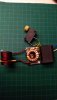
The other accomplishment I was looking for was another level of compactness. This required another strategy that I've avoided so far, drilling holes in the board. I put the capacitor at the very edge of the board and stood it up. This provided access to 4 holes for the inductor, and in turn, it leaves plenty of room on the board for a robust coil.
View attachment 1839
Backside is treated as before. This is the board with the common ground plane. This made termination and the switch location very simple.
We are now within the confines of the printer circuit board including the coil. And it also accounts for a full 20mm coil length. That makes the envelope 56x38x38 including the wires and the switch.
View attachment 1840
I don't thin I'll keep the coil orientation this way. I still have enough 12 gauge to wind a coil that stands up off the board. At 11 turns, it draws close to 80 watts at 12 volts on an '18 SS tip. That is perfect. Earlier I said it was tamer but that was the Ti tip. I should keep these straight. the '18 tip and cap is the best coupling pair for these tests.
Also remember that when you drill the board, there is no plated via. Note the wire between the capacitor lead and the coil lead. On this board, both sides have the coil trace. Be sure you account for the beefiness of the current path. I am not sure I can do this cleanly with my other boards. I might have to flip the board for better trace access.
There is still one curiosity to this circuit; It still draws a lot of extra current when 'idle'. I will have to see if coil orientation has anything to do with it. I also don't know if inductors interfere with capacitors. Or, in this case, it could easily be due to the extra windings on the inductor.
One last observation; I have the lower voltage FETs on this board from the MOSFET switch. They do get warm in this configuration. I think it was more efficient with both capacitors. I will add some beefier copper traces when I mount another coil. Right now, it's 7 seconds to the click on an '18 SS tip. And it's set for HOT.
One thing I am confident of, if you have 18 gauge magnet wire, you could rewind a HalfPint coil with maybe 36 inches of wire. Run 15 turns, leave a tap-length and continue with another 15 turns. Now you have a center-tap length without scraping. Likewise, I could have stopped with the parallel winding when it rejoined at 31 turns or so [extra turns wont hurt]. The take-away is to have equal lengths on both legs. A parallel winding will make sure the core saturation peek is optimal. I will be testing this one to the hilt to see if I'm stressing anything. This is definitely limited to around 80 watts with these lower voltage FETs.


.jpg")
 But, thanks for making me think about it. Maybe I'll have to get on that's specially shielded somehow!
")


") Nice work so far! I'm looking to do something similar and have been working on a direct-to-piece IH, just with the stock ZVS driver for now. Spicy!
Nice work so far! I'm looking to do something similar and have been working on a direct-to-piece IH, just with the stock ZVS driver for now. Spicy! This has pretty much occupied my time during this lock-down.


 ). I think the creativity will lie in how it's tuned. Great info!


 Even being a mechanical guy, I suck at "how many marbles in the jar" contests.


