DIY Induction Heater Builds and References

TheThriftDrifter

Land of the long vapor cloud
Hi everybody!
I just want to show how happy I am that TommyDee is miniaturising the whole IH / vapcap world. ;) ... this is my interpretation of the "half pint":


Beautifully done. Any chance of a vid?

@TommyDee . That is small. Looks Jetsons futuristic. I never would have thought to use a wood cylinder as a spacer. Two very exciting heaters guys! 🤩
 

TommyDee

Vaporitor
I have two candidates for housing. The tabletop can use a 'facade' cover. I have an idea. Need to do some shopping. The 'wand' is just what it is. Convenient as a ReHeat'r but still too bulky for a wand. Size after this for a wand adds thermal risks. A wand probably needs to go more conventional on the coil. Maybe the 2S coil will work well as a single-depth 7 turn coil.

This is what I can see being good HalfPint implementations. These units both feature a 15mm ID double would coil, 11.1v optimized performance, and an optimized standard ZVS circuit board.

20200606_163421.jpg
20200606_162826.jpg

...I FEEL SOILED!
My entire DIY career...
55+ years of MacGyver'ng!
And I had to go and...
FUCKING USE HOT GLUE!
..of all the low down...
That's lower than ...
JB-Weld on a Hot-Rod!
Got an idea for charging finally. I'm going to try an old standby - the Li-Po chargers are suppose to work on li-ion cells the same. I found the old DC unit that has a fairly wide input range for $10. That will take care of having to have exactly 12.6V from the wall wart. I don't trust those things that far. I want to give it 15V and forget it.
 
Last edited:

TommyDee

Vaporitor
Today I recycled 2 coke bottles for a good purpose. Of course, I also wasted several ounces of ABS plastic getting to this point. I actually got a decent 2-tone cover but it warped. Nice touch but not for this design. My PLA selection sucks, and another ABS just plain failed. So, PETG to the rescue. PETG is also known as Coke bottles. Naturally translucent it makes for a tough yet somewhat flexible structures. This is a simple top and bottom shell. Both have the open honeycomb pattern.

The "HP" stands for HalfPint. The entire unit has 2 16 gauge silicon rubber power leads hardwired between the ZVS board and the battery case. The batteries are removable for charging. The battery case is free to be removed from the case while the ZVS board is tacked down at the capacitor on the floor, and along 2 adjacent edges along the wall. This 'fixing' with hot glue also stabilized the relatively thin constitution of the box.

20200607_210143.jpg 20200607_210120.jpg

And HalfPint it's a cordless coffee table unit that can go outside for a quick puff. With the hexagon texture and the 'softness' of the thin PETG makes this IH 'easy' to handle. Enough heft to hold fast on a surface but definitely light enough to use as a torch. A single button to push, a blue LED on-board to indicate heating, and an adjustable-depth cup for heating preferences. All within a 4"x4"x1" brick weighing in at under 7-oz.
 

NexVision

Well-Known Member
Today I recycled 2 coke bottles for a good purpose. Of course, I also wasted several ounces of ABS plastic getting to this point. I actually got a decent 2-tone cover but it warped. Nice touch but not for this design. My PLA selection sucks, and another ABS just plain failed. So, PETG to the rescue. PETG is also known as Coke bottles. Naturally translucent it makes for a tough yet somewhat flexible structures. This is a simple top and bottom shell. Both have the open honeycomb pattern.

The "HP" stands for HalfPint. The entire unit has 2 16 gauge silicon rubber power leads hardwired between the ZVS board and the battery case. The batteries are removable for charging. The battery case is free to be removed from the case while the ZVS board is tacked down at the capacitor on the floor, and along 2 adjacent edges along the wall. This 'fixing' with hot glue also stabilized the relatively thin constitution of the box.

View attachment 1288 View attachment 1289

And HalfPint it's a cordless coffee table unit that can go outside for a quick puff. With the hexagon texture and the 'softness' of the thin PETG makes this IH 'easy' to handle. Enough heft to hold fast on a surface but definitely light enough to use as a torch. A single button to push, a blue LED on-board to indicate heating, and an adjustable-depth cup for heating preferences. All within a 4"x4"x1" brick weighing in at under 7-oz.
I'll take 2 they ready yet?
 
NexVision,
  • Like
Reactions: TommyDee

TommyDee

Vaporitor
We should gather a consortium of makers and do artisan commissions. People make modules, others make cases, and another consolidates.

This would be highly inappropriate as a product considering it doesn't even have a proper fuse. This is minimalist to the max!
The only thing managed with this is thermal. Nothings gets stupid-hot with normal use. And nothing except a fault condition will leave the unit running.
If anything ever goes stupid, I have a big yard to toss the flaming embers onto. Overnight, the batteries are charging and out of the unit.
 

CaleidosCope

Well-Known Member
We should gather a consortium of makers and do artisan commissions. People make modules, others make cases, and another consolidates.

This would be highly inappropriate as a product considering it doesn't even have a proper fuse. This is minimalist to the max!
The only thing managed with this is thermal. Nothings gets stupid-hot with normal use. And nothing except a fault condition will leave the unit running.
If anything ever goes stupid, I have a big yard to toss the flaming embers onto. Overnight, the batteries are charging and out of the unit.
Good point. I talked to someone into electric stuff... he raised the eyebrows and told me whatever frequencies leave the unit could be harmful. So, no pacemakers please! I will pass him over a standard and a half-pint to do some testings. I will report.
 

TommyDee

Vaporitor
We're in the 20-kilohertz range. Basic radio band. I'm sure these things would light up an RF meter. But there are open bands for such nonsense.

Got a good size spool of 18 gauge magnet wire today. Let's see if I can make some proper center-tapped coils.

I'm pretty close to pulling a trigger on a dual USB scope. Maddening search commences.
 
Last edited:
TommyDee,

TommyDee

Vaporitor
DS213 - looks like a nice little hobby scope.

I was grocery shopping today looking for some DIY kit things. Ran across some very small automotive fuses. This will solve the passive fuse issue.

I also made 2 new coils. I took the compressed coil concept to another level by making 9 turns and then coming back with 2-1/2 more for a total of 11-1/2 turns . Now the coil length is more proportional to the cap and the extra winds make sure the impedance is closer to original. I also opted for a 16mm ID. Mounted this on the "Standard" IH and it is looking sharp. Being a full circuit, this things runs up past 80 watts quickly. This setup will easily fit in a full true 2-1/2" cube as a stand-alone heater with lots of power.

Also rewound one of the original coils. Carefully straighten out the wire working it as little as possible to avoid work-hardening the copper. I wound it to a conventional 8-turn coil on the 16mm mandrel. It works fine, very hot! but not quite there at 6V performance or even 7.2V. 7-turn and 10 gauge should perform much better for 2S applications.

This is my next quest just to put it behind me. This will stuff into a volume of 2-1/2"^3 comfortably.

20200611_122958.jpg

Right now I am considering hardwired leads to battery pack. The pack will drop out of the case to change cells. The pack will have a mini-fuse hardwired in place of one of the joining wires. Recommendations is to have 3 cells in the charger and 3 in use. Always ready to go; or do the overnight charge. Alternatively I could hook up BMS, meters, and lights and make it all messy. It would even fit in a 3/8" narrower width if a cubical presentation were moot.
 
Last edited:

CaleidosCope

Well-Known Member
Just to complete my saga. This is the end of my half-pint wired project... don't ask me... I literally soldered some stuff while the box was closed. Tiny. Nice to hold while drawing. The tubing light (led on the bottom inserted in an silicone plug) gives help to know what's going on while this thing is in your face. So next challenge : HalfPint plus 1000mA LiPo-pack


Last edited:

TommyDee

Vaporitor
This didn't belong in the fluxer thread; here

As the (3) 18650’s voltage slowly drops, the 1st DV click timings will slowly grow as well. If you get 1st click at 4-5 seconds while batteries are freshly charged at about 12 volts, after much use, and total voltage drops to 10.6 volts, the 1st click will take longer, 7-?, (I’m still testing), but longer 1st click times are another clue, besides battery voltage, that it’s time to charge batteries. BTW: Fluxer’s with battery life switch/LED, the green-green/red- red LED’s, are surprisingly accurate indicators of remaining battery life.

The tuning of the circuit, the part that Mr C does in design, determines the power level that affects heating. Speaking on generic modules, which act similarly, yes. And I'll provide the caveats to this observation. It may also help to understand the Fluxer/Flix coil choices.

Please note that I started and have used the stock ZVS circuit coils for a long time. The are open and airy. This is the intent of an induction heater to generate its most efficient magnetic field. Very 'forgiving' coil. Insertion depth didn't matter much because the entire cap was bathed in a fairly homogeneous magnetic field. Settling on 60 watts as a good heating rate, I enjoyed that setup immensely. One little niggle - it also vapes the resins in the cooling fins making for crumbly deposits that don't wash away easily.

I started working coils to see what happens. Mostly I was interested in the circuit variation but I quickly learned to mind the size of the magnetic field. I quickly figured out that small also means less 'generic'. I went down to a 16mm ID on a short coil and learned that 2mm can take the load from green taste to burnt. A slightly longer coil improved that but still very sensitive.

I still fire with 3 coils at the moment. I can manage any of them. However, they are not 'right' to my tastes. But that doesn't matter as yet. However, I am not one to make an aggressive coil the standard. I'd rather have more margin on time. 8-10 seconds heatup is a good balance or me. If I crank that output up to 12V, it'll double click in 5 seconds with any of the coils.

By the same token, I got the click to change several seconds by moving the cup in the smaller coils. This is where I started to notice these were not quite as forgiving. They draw the same power but the intensity of the field is no longer as homogeneous as before with the longer coil. So the clicker is 'left out' It isn't being heated by the magnetic field as much and the temperature must migrate from the hot spot on the cap to the clicker. This can loosely be associated with hysteresis in a 'circuit' but it is compounded by the fact that the magnetic field's influence on heating the clicker also changes when you move the cap within the coil. Double whammy. Therefore, effect-by-the-millimeter is device dependent. In the discussion so far, I am fairly confident that a millimeter of movement of the coil in relation to the VC can have a 2-3 second change in timing and cook time based on the Fluxer/Flix design. This time difference will decrease as you enter the margins of the usable range.

I happened upon those battery meters. I put one in my flat-pack IH. That little HalfPint is running high on the list of favorites. That is the unit that is teaching me about recognizing a low battery charge based on performance. At 9V under load, it never reaches the second click before dipping below the minimum voltage. 9V is the typical safety cutoff for 3S li-ion. I think it is running at a 35 watt range at that time. Therefore, since the cells ae sized for my daily use, if toward the end of the day if starts to lack performance, I should know intuitively where my cells charge state is just by using it. It also means I've overdone my day and I should just lay down the VC.

Nice write up TommyDee.
Having only my SKJ IH previous to my FD, I’m curious what if anything is used on IH units like the Apollo, to keep the hot DV tip, from the push down switch? As you know the FD has a tiny glass button glued to the top of the switch, so it can’t melt. Do the commercial IH devices use the same or similar switches, and are they left stick/bare?
Thanks.


I think the VC-activated switch is the genesis of each of the artisan heaters. They all had to deal with it. I've simply (a)voided it. This is not a simple problem. My take is an offset switch with an actuator in the bottom of the coil. Regardless, there is a lot of heat. I'm settling for wooden cups and I'll need something like Oak to keep it from continually charring.

I believe that these switches have also complicated the usefulness of making the VC position in the coil adjustable. I think the relationship should be adjustable.

Let me give you a fun alternative to the switch for design... What about 2 flexible contacts as a switch? Let the cap complete the circuit.
Come to think of it, if those contacts were on an adjustable pedestal, one could adjust the insertion depth as well. You can use aluminum around the coil for hardware.

View attachment 1515

Sorry, thought you had an Apollo at one point. I’ll see if I can find a photo online, or perhaps someone that has one can reply?

As far as using the cap to make the circuit, it was either in this thread or the old one, if you recall someone tried something similar, but the metal acted as a heat sink, so NG. Seems if the switch is going to at the bottom of the coil, it needs some type of non metal insulator. I know Mr. C, looked long and hard on this subject, thus I was interested in how other builders, especially the commercial ones, have approached this issue.

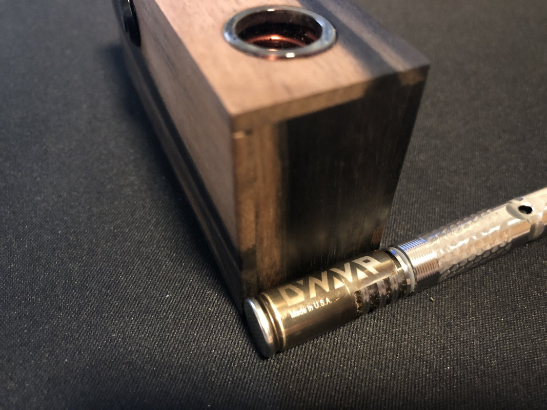
@RustyOldNail It look like it's a silicone cap at the bottom of my apollo. It's the same thing on both models.View attachment 1518View attachment 1519


Yes, Apollo uses a silicone switch button.

I suppose a pair of pogo pins would eliminate the heat transfer. I'll play with it some.

Also, there are metallic RF-compatible materials. When I put my hobby knife handle in the IH it only pulls an extra 3 watts. That says aluminum will work.

We should move this discussion to the generic IH discussion thread though.. @Stu ?

Thank you for taking your time to take photos & post! That’s very interesting, wonder what temperature that silicone is rated for? The switch on the FD is high temp rated, but from my limited understanding, most of the custom coil choices Mr. C offers can run hotter, then the types used in many of the commercial ones, and thus if a DV sits too long on a bare plastic/composite switch, can melt it, (photos in this or OGFC thread). The glass button solution he employs works great. I was just curious. Thanks.

group_shot_switch_boots-650x431.jpg
Switch boots.
silver-300g-tactile-switch-with-spherical-actuator.jpg
metal dome switch

Okay, back to Fluxer...

I found the image you were talking about... Is this it?

View attachment 1520
 
Last edited:
TommyDee,

TommyDee

Vaporitor
Interesting news regarding the IH circuits.

Today I blew one up. These MOSFETS do exactly what our old hobby speed controllers did, they short closed. That means the board sees a short with resistance when powered. if that happens as the single fault failure, that could make the 'product' unsafe. A fuse, thermal fuse, or BMS takes care of that. I clamped the 20 amp BMS when this one failed.

And I failed it. Have no doubt these circuits are robust, but they can take excess loads. I made the mistake of trying a "quick test". I know, famous last words. Like "Watch This!" and my first reaction is to draw the camera ready to win America's Funniest Home Videos. I tried to put a piece of regular metal tube in the IH. IH's loves high carbon steel. My meter was adjusting and 'POP'. Probably tried pulling 400 watts into the system.

PLEASE DON'T PUT OTHER SHIT IN YOUR IH!
...but if you're stupid like me and just go for broke, well, I have a tip for you.

Tip1 - replacing MOSFETs sux. They solder on easy but now you have 3 leads to lift. The base and 2 legs. Be -very- careful with the pads on the IH board. The typical method is a specific type of hot air gun but this board doesn't lend itself to repair with general DIY tools. I used a 60W iron with a broad chisel tip. Flux and solder to get a good heating going on the edge of the mosfet to get the base solder loose. I twisted the iron to get the part to lift, although not quite released. next I shove the tip under the mosfet until it was free of the solder connection -to the base-. The two legs are still attached. Now heat one leg while tipping the device away from that leg. Unsolder the remaining leg.

Dead FETs removed. Clean the board up from the extra solder still being mindful about applying excess heat. You need the pad somewhat level. The replacement will need the copper heat-sinking of the board without the excess solder acting as a thermal insulator.

Tip2 - You just removed 2 D06 N-Channel MOSFETs from the IH. How does it feel? ready to do it again? You are about to replace them with D4184 N-Channel MOSFETs. At least, that is what my standard model Mini ZVS IH circuit used and the the MOSFET switches I have. I did go through the specs and D4184 are not nearly as juicy, but their specs are still within reason. Not being an EE in this instance may be a positive factor. However, I did do the cursory assurances of pin-out, power ratings, and basic fitness comparisons. In this instance, The original MOSFETs appear to be about 20% more FET so to speak. We shouldn't need that for a lower powered IH. Now mind you, I did test this unit to 75 watts. I don't know what will happened at say 100 watts. Also note this is replaced on a full ZVS circuit, not HalfPint. To remove the two FETs from the MOSFET switch, do the same thing. Put the little board in a vice and heat the large tab and pry the device with the iron-tip if you can. This time you can fuck up the circuit board to your heart's content. Clean the solder from the back of the device and make sure it is clean. Watch out for excess device heating but also tin and clean the 2 legs.

Tip3 - You now have a clean IH board with no MOSFETS and 2 clean MOSFET switch FETs to place on the board. I'll describe 1 but you can do both simultaneously. Place the FET on the pads and tack down one of the pair of leads to hold the thing steady. Use something to push down on FET for this next trick. The FET should be flush with the board. I don't prefer the prep-work required for that. So use the flux generously and place the iron-tip at the edge of the FET large leg and the board. Get it hot so you know solder flowed under. Drop the solder and push the FET down with a 'pointer'. I use a hobby knife. This ensure good contact with a lot less work. Go back an secure the other two leads. If you are as OCD as me, you will also push the "S" leg down to the board. I don't want solder acting as a mini-resistor at this junction. Clean the flux up and you're done.

Now put the coils back since you needed to remove to get to these FETs. Give it some power and see if your soldering skills are better than you thought. If the light comes on, you're in fat city.

So how many of you DYI'rs have a toasted ZVS board or two laying around? Did you also use the MOSFET switch? In that case, you have what you need to attempt a repair.

20200615_205039.jpg

Datasheets N06 & D4184 . Note the LED is lit! This is the ReHeat'R circuit with the 2 coils on the other side with the 2 caps.
 
Last edited:

Edgedamage

Well-Known Member
I found this project box at my local electronics store. So the R2D2 drink cup got gutted and all the parts where stuffed in this box. The only real hack I had to do was move the inductors away from the main board.

Parts I stuffed in the box:

3X 18650's

BMS

3s charger

15A 400W MOS FET Trigger Switch

Induction heater

12v lighted switch

Battery level meter

XJ60 connectors

Iwodevape Replacement Glass Tank for Cloupor Cloutank M3

Cooling magnet

lt9h953los551.jpg
 
Last edited:

Edgedamage

Well-Known Member
Thank you. Now I have some questions:
#1 Are you running your test board off one inductor? If so is bridged to both FETS?
#2 I know these boards can pull 6 to 7 amps when used for with a vapcap. Your cutting the trace and placing a switch there is the switch seeing the full current draw?
Thanks for your time.
 
Edgedamage,

Edgedamage

Well-Known Member
Dollar store memories box build. Another battery based build with onboard charging.20200521_080056-COLLAGE.jpg
 
Edgedamage,

TommyDee

Vaporitor
Hey @Edgedamage - I am running the board on two inductors with a shared core. I count windings directly to the middle and scrape the insulation so I can add positive potential right there. Effectively, I cut the coil in half. It should cut the down from 100uh to 50uh. Within an IH circuit, this changes the frequency. I also removed one of the caps. That is what makes it a "HalfPint". I noticed the Apollo 2 only has one cap and that is what gave me the idea to cut the circuit in half.

Cutting the trace is board dependent. I have 3 versions and they all treat that trace differently. Follow the circuit. On some, the 3-pin output connector, center pin, is connected to the middle termination between the inductors. Some are not. I make sure the power lead from the positive input connector, the 2-pin connector, that the trace fully powers the 470 ohm resistors. There may be vias along that trace that need to be removed from positive input voltage. The remaining trace can be cut to disconnect the positive input voltage. By doing this, isolating the gate circuit, you can use a switch that will drive only the LED, mere milliamps, and 'signal' the gate circuit. Signal means it only requires voltage to the gate, it does not draw current. So the switch has very little power going through it. It is the very same as the switch you use for the MOSFET switch which becomes redundant with the circuit I am describing.

Joanne's and Covid just don't work well together. Amazing how patient their customers are. Drives me postal!
 
Last edited:
TommyDee,

Edgedamage

Well-Known Member
Hey @Edgedamage - I am running the board on two inductors with a shared core. I count windings directly to the middle and scrape the insulation so I can add positive potential right there. Effectively, I cut the coil in half. It should cut the down from 100uh to 50uh. Within an IH circuit, this changes the frequency. I also removed one of the caps. That is what makes it a "HalfPint". I noticed the Apollo 2 only has one cap and that is what gave me the idea to cut the circuit in half.

Cutting the trace is board dependent. I have 3 versions and they all treat that trace differently. Follow the circuit. On some, the 3-pin output connector, center pin, is connected to the middle termination between the inductors. Some are not. I make sure the power lead from the positive input connector, the 2-pin connector, that the trace fully powers the 470 ohm resistors. There may be vias along that trace that need to be removed from positive input voltage. The remaining trace can be cut to disconnect the positive input voltage. By doing this, isolating the gate circuit, you can use a switch that will drive only the LED, mere milliamps, and 'signal' the gate circuit. Signal means it only requires voltage to the gate, it does not draw current. So the switch has very little power going through it. It is the very same as the switch you use for the MOSFET switch which becomes redundant with the circuit I am describing.

Joanne's and Covid just don't work well together. Amazing how patient their customers are. Drives me postal!
Sorry but I seen on the first page one you made called the halfpint it has only one yellow inductor. And one cap that's the one I was asking about.
 
Edgedamage,
  • Like
Reactions: TommyDee

Mono Loco

Well-Known Member
Good point. I talked to someone into electric stuff... he raised the eyebrows and told me whatever frequencies leave the unit could be harmful. So, no pacemakers please!
Hmmm ... as a host of a Pacemaker (actually, a fancy double-duty one that also has a built-in defibrillator = ICD) this caught my attention. I never considered it. I don't want to discuss this with my cardiologist, but I'd like to know more about it. With whom should I discuss it, I wonder? Perhaps the ICD manufacturer (Medtronic) would be the best source. Dang ... why did I have to see this?????? :rolleyes: But, thanks for making me think about it. Maybe I'll have to get on that's specially shielded somehow!

edit:
I just found this, regarding the use of Induction Stove tops.
"Induction cooktops produce electromagnetic fields (EMF) which may impact pacemakers and ICDs (Implanted Cardiac Devices). Notice in Induction Cooktop Use and Care Manual:"CAUTION: Persons with a pacemaker or similar medical device should exercise caution when using or standing near an induction unit, while it is in operation. The electromagnetic field may affect the working of the pacemaker or similar medical device. It is advisable to consult your doctor or the pacemaker manufacturer about your particular situation. We recommend that induction cooktop users with pacemakers should consult their doctors or pacemaker manufacturer regarding EMF levels and use of EMF producing equipment."

That's a pretty generic warning. Maybe at 12v DC, the little I.H.s for Dynavaps are not significant ... of course, that's just me standing in that river in Egypt ... da' Nile!!!!
 
Last edited:
Mono Loco,

TommyDee

Vaporitor
Sorry but I seen on the first page one you made called the halfpint it has only one yellow inductor. And one cap that's the one I was asking about.
Yes, that is what I am describing.
20200603_133634.jpg
49831805072_268998b5fa_c.jpg


That is a center-tap connection.

These are the the two legs -

20200429_133409.jpg

This also makes the inductor stable [3-legged stool].

@Mono Loco - a good friend has a pacemaker. he says he 'feels' magnets nearby. Not sure what that means.

I wear wireless headphones without any noise or hum. These are made to concentrate power, not radiate it.
Most PWM motors work in this same frequency range and similar magnetic fields.

Of course, I am not a doctor or a medical device maker, but you are looking at a range that most heavy power switching devices operate in. Battery powered drills may be a similar device. Cooktops and microwaves are in their own category but yes, those are 1,000 watts and the IH is 100 watts only when the VC is inserted. As an antenna, idle, it can push up to 20 watts. As RF, that's some juice. I think Fluxer runs in the range of 20mhz IIRC. Literature for inductor range is 47-100uh. That is the second reason HalfPint made sense as a simple mod.
 
Last edited:
TommyDee,

Edgedamage

Well-Known Member
Ok I think I got it now, you solder the two factory leads to the cap leads. Then you solder a center tap to middle of the coil, then solder that to the positive rail. Or solder it to a switch connected to the power rail. Also thanks for the pictures really helped.
 
Edgedamage,
Top Bottom