A quick add on to my above post:
I have started using the one piece ego drip tip. I like the one piece because it's easier to remove while unit still hot. The two piece wants to separate at the 510 tip. Save some coin as well. Many out there, just google "ego drip tip type b".
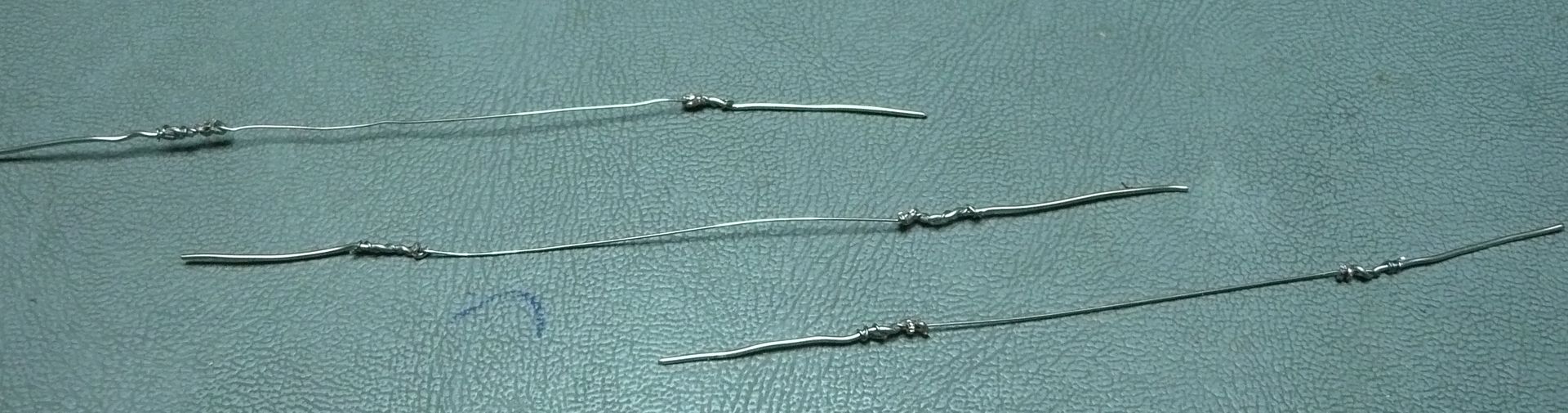
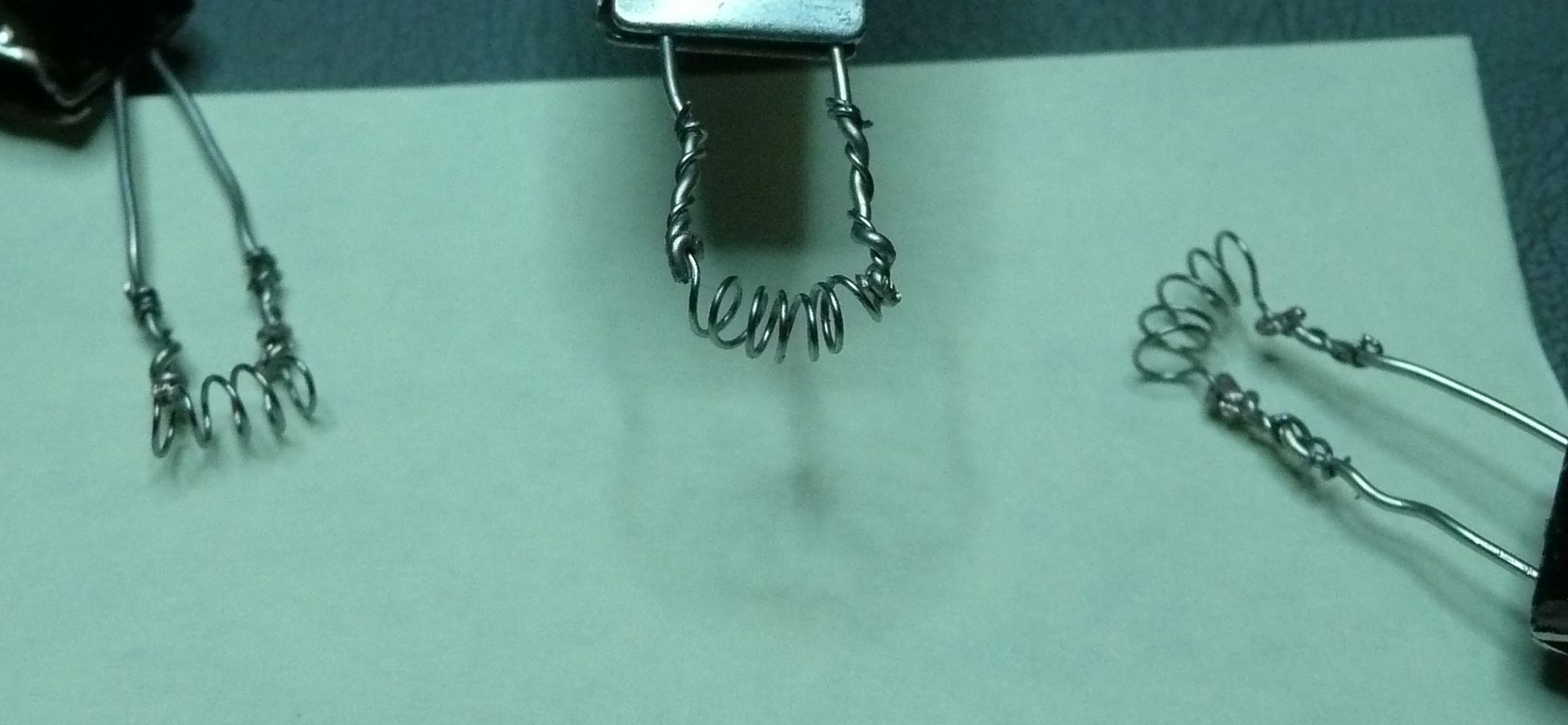
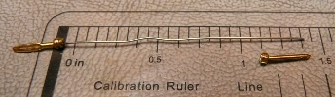
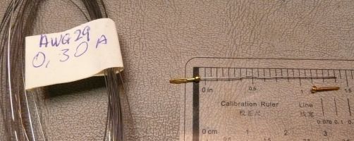
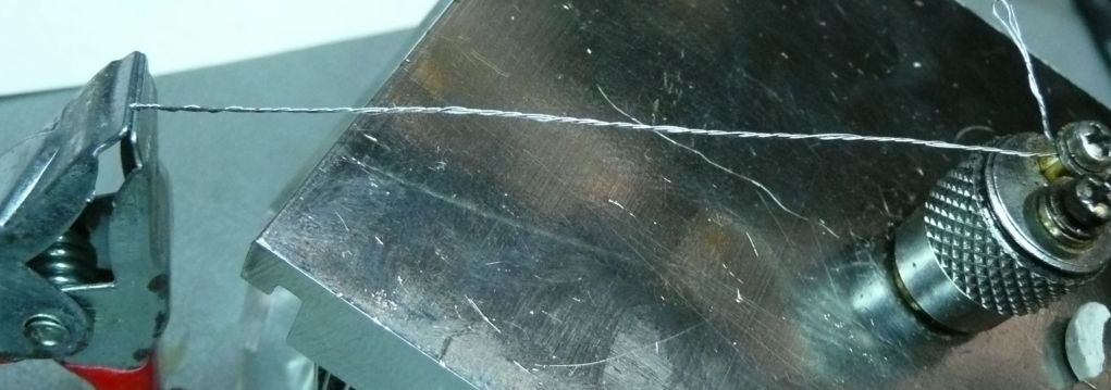
Also, the single coil element IMO is the way to go. 30 AWG Kanthal type A. For 6 volt 3 ohms or 4.5 inches seems good.
NEW CHEAP ALTERNATIVE:
I was searching around the web and found China has started making Bulli Clones and caught my eye.
The main thing which really got my interest was the price. Under $5 a unit with the catch being minimum quantities. I would imagine soon to be available in local ecig shops.
Well had to take check them out. I ordered a test sample pack to experiment with.
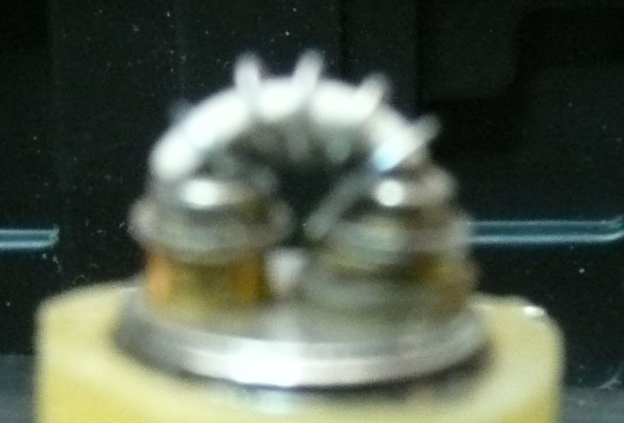
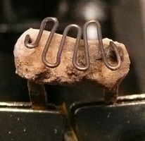
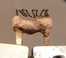
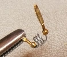
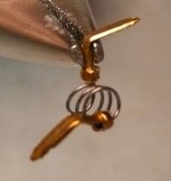
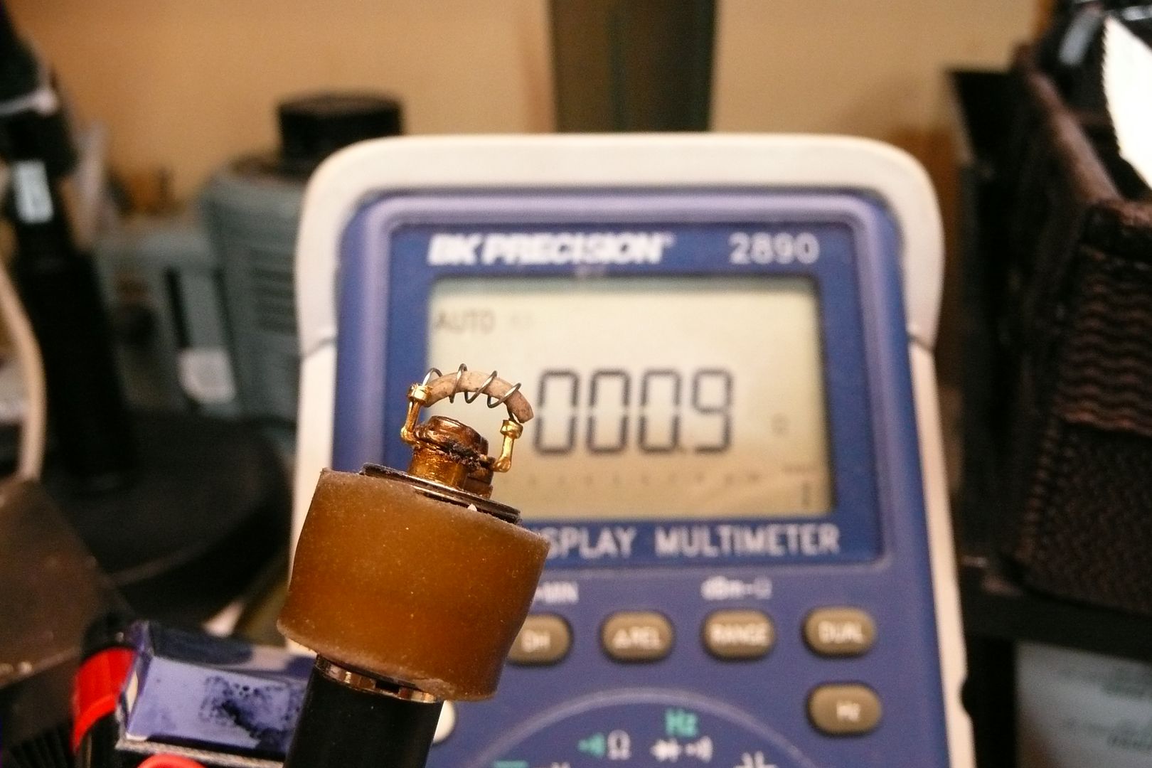
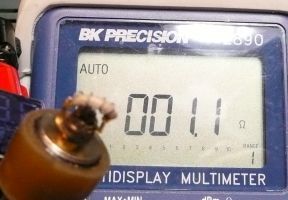
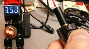
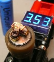
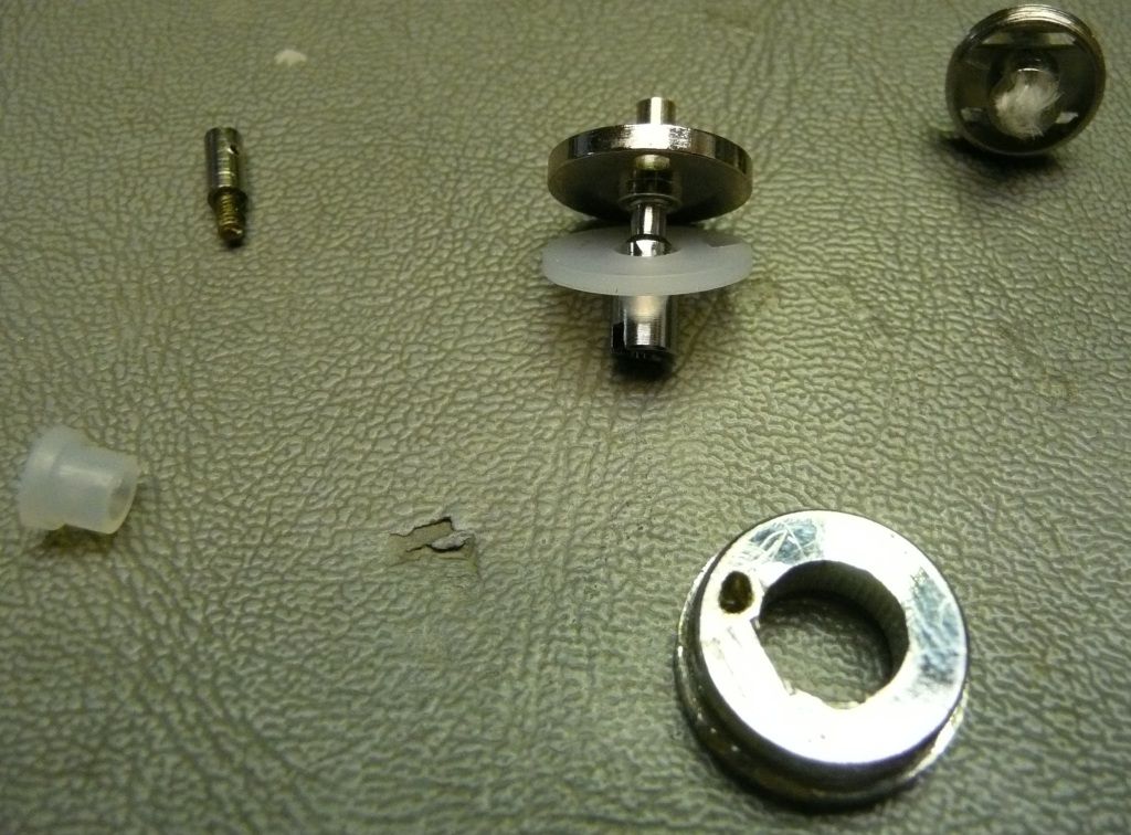
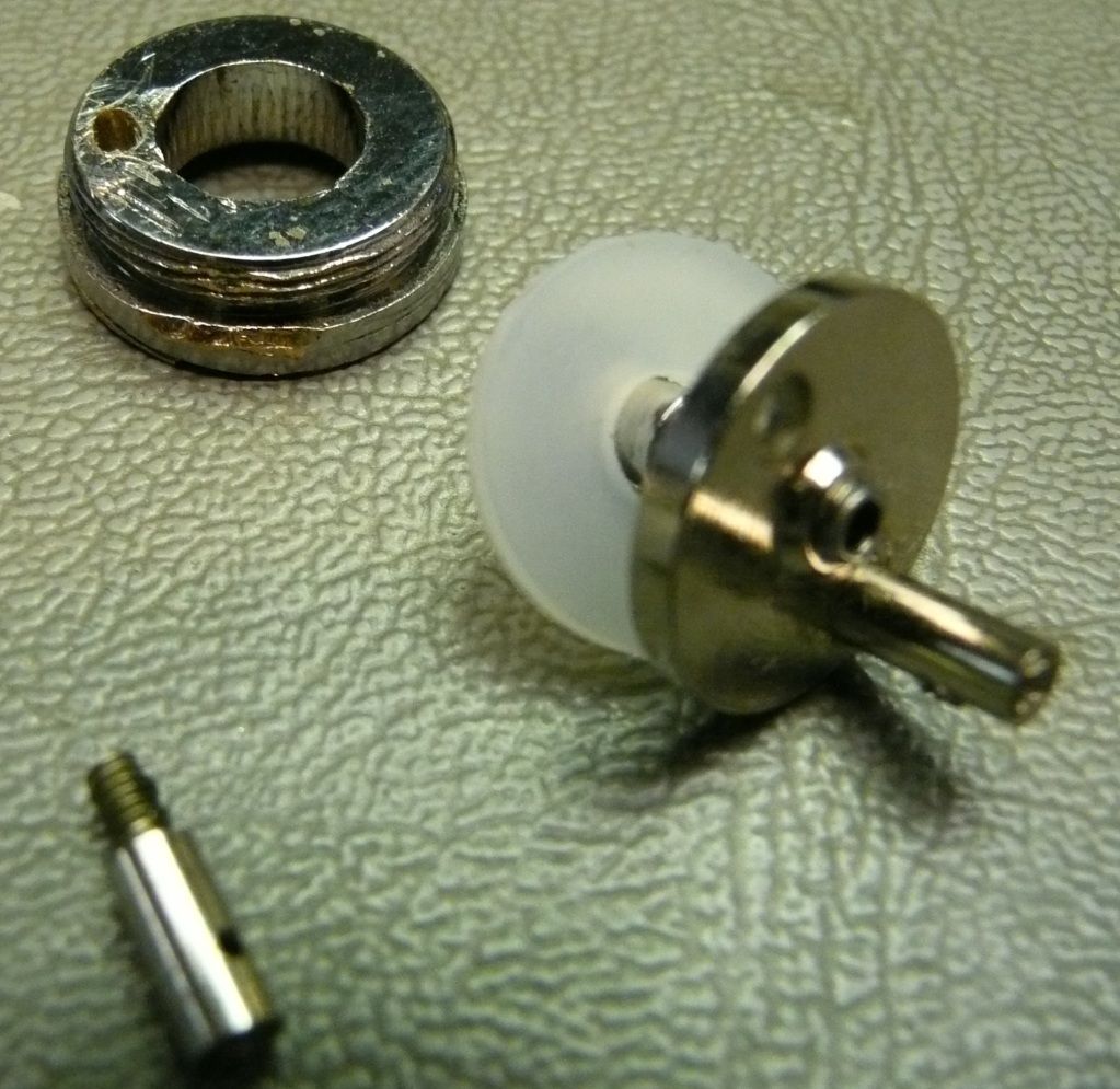
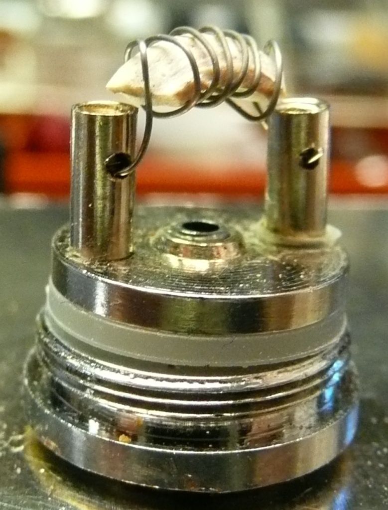
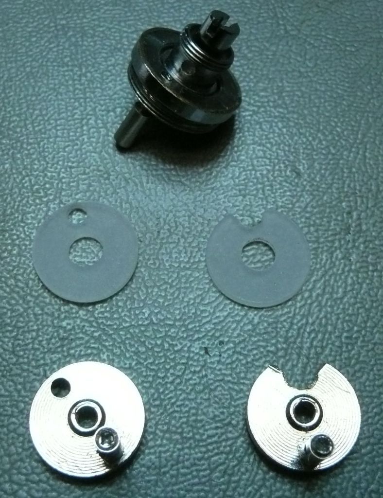
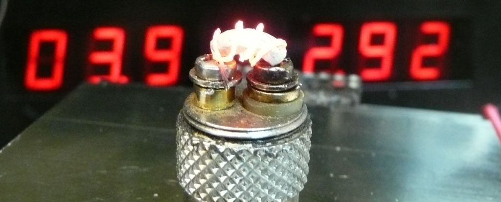
They come pre-coiled with a 3.5 ohm element. The center plate with puncher pin un-screws rather than pressure fit.
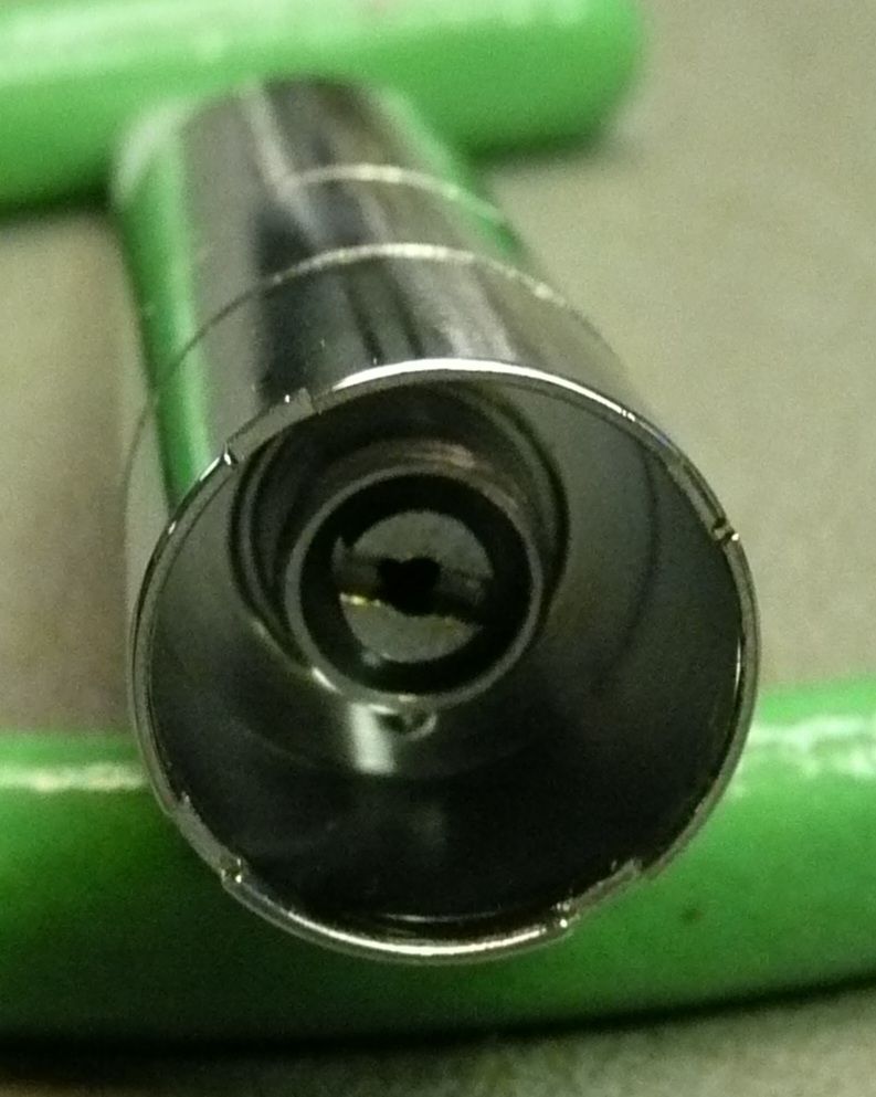
The size of that puncher pin is crazy. The tank does not come with a cap. I thought that was odd as is the only thing missing besides the ejuice and battery to get it up and going for ejuice users.
Right away I ran into a noticeable problem.
The skirt is not removeable. Dam, I thought it was as I discovered there are more than one type of clone. Anyway, have to work with what I got.
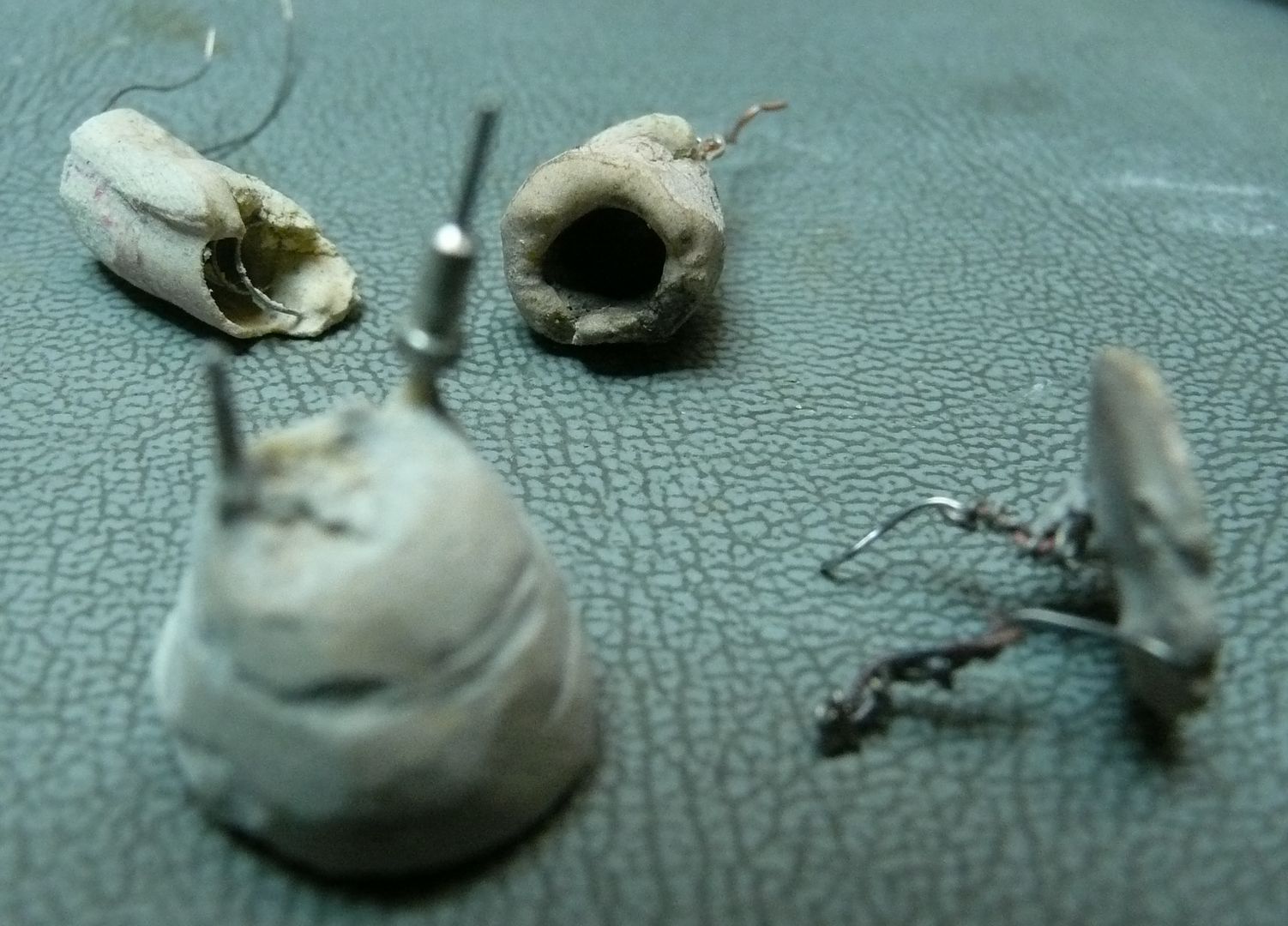
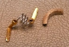
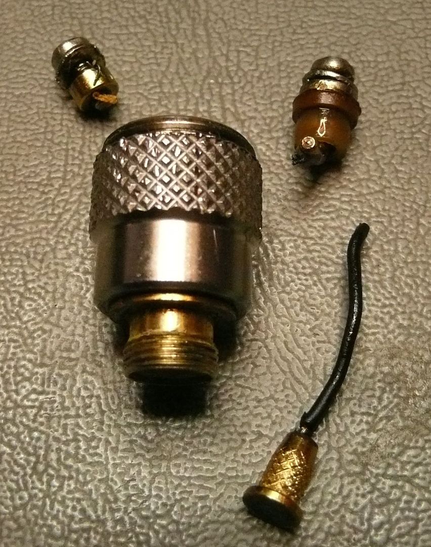
My first impression was that these things are cheap, cheap, cheaply made. Material is that brassy looking stuff and is brittle as hell. At least this made it easy to break away that skirt. Now as for the actually design, I have to admit it's very clever how they put it together. Of course the first thing I did was sacrifice a unit to see how it's put together.
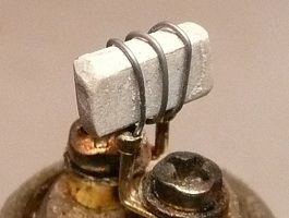
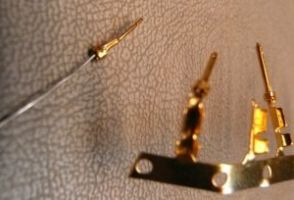
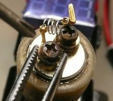
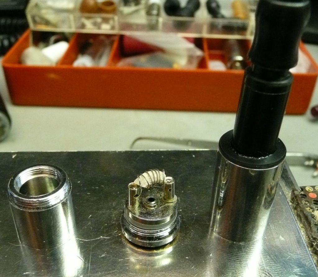
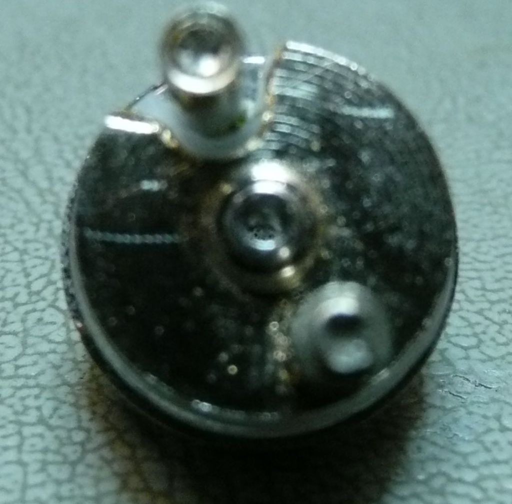
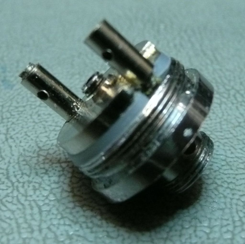
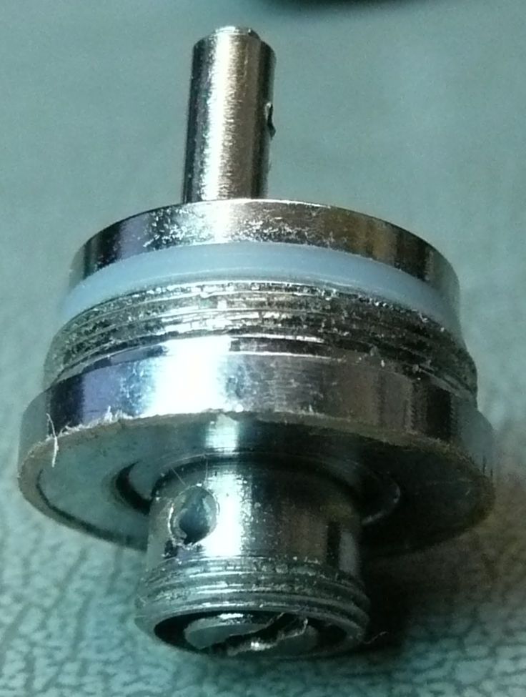
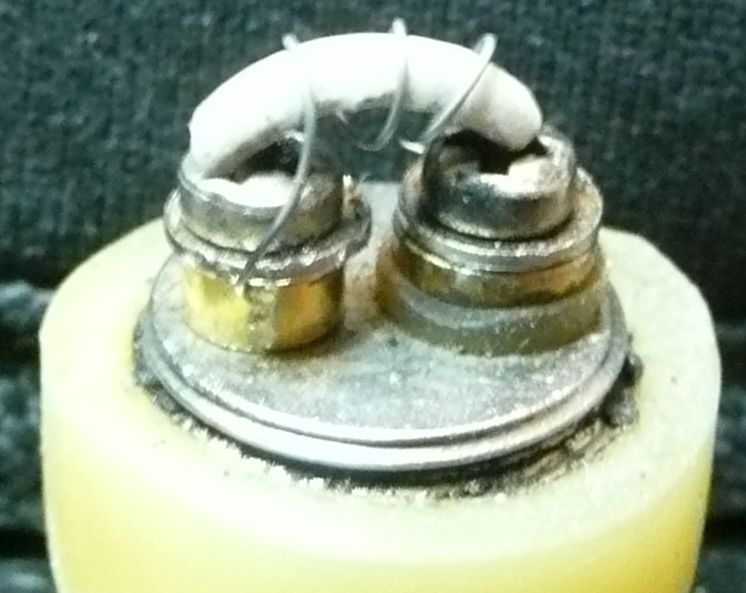
A big electrical difference is the center pin of the 510 connector is threaded into a circular plate which has the positive post mounted on it. This is the complete positive side of the circuit. The ground pin is screwed through a hole in this disc with a thin piece of silicone insulator. This is one of the weak points of the design. The method they use to attach the heating wire is using very small screws which go down the posts and press the element via small holes in the side of posts. These are very flimsy the philips head strips very easily. A proper fit screw driver is a must here. I do not think this unit would hold up well for multiple rebuilding. But for once or twice......
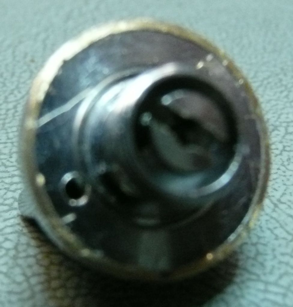
Air path is also quite different. This unit draws air up through the center pin as to support automatic batteries I guess. At first I was a little disappointed as again like with the skirt I thought I saw holes in the pictures. Must have been a different clone. There is another one called the "Bully" spelled different. I think that this the one with holes and removable skirt. Anyway, the holes on the sides of the 510 threaded piece IMO were too small. I drilled them to 1/16" and seems OK. I left the single hole in the center alone.
Unit overall mass is much less and the actual base is about 3 mm shorter with skirt removed. Causes heat differences.
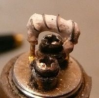
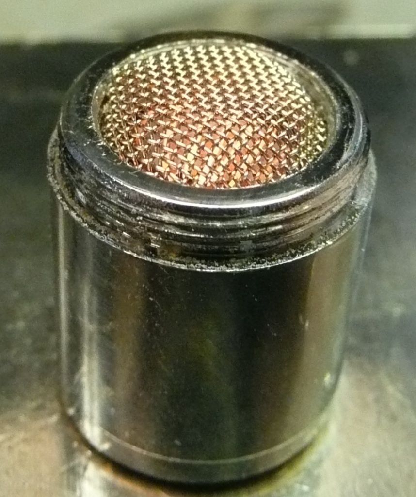
The rest of the mod is pretty much the same as with the original Bulli TM mod. The center portion screen hole part is a little smaller and threaded instead of a rim grooved like the Bulli. The juice tank piercing spike plate is removed by unscrewing it instead of popping out.
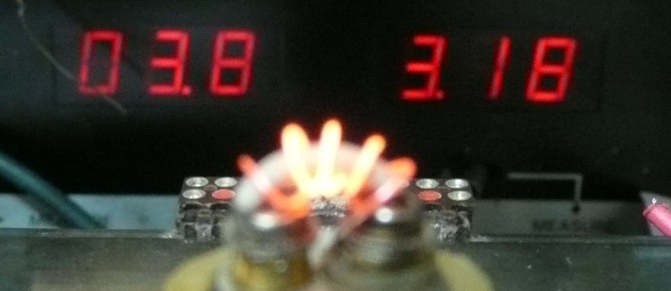
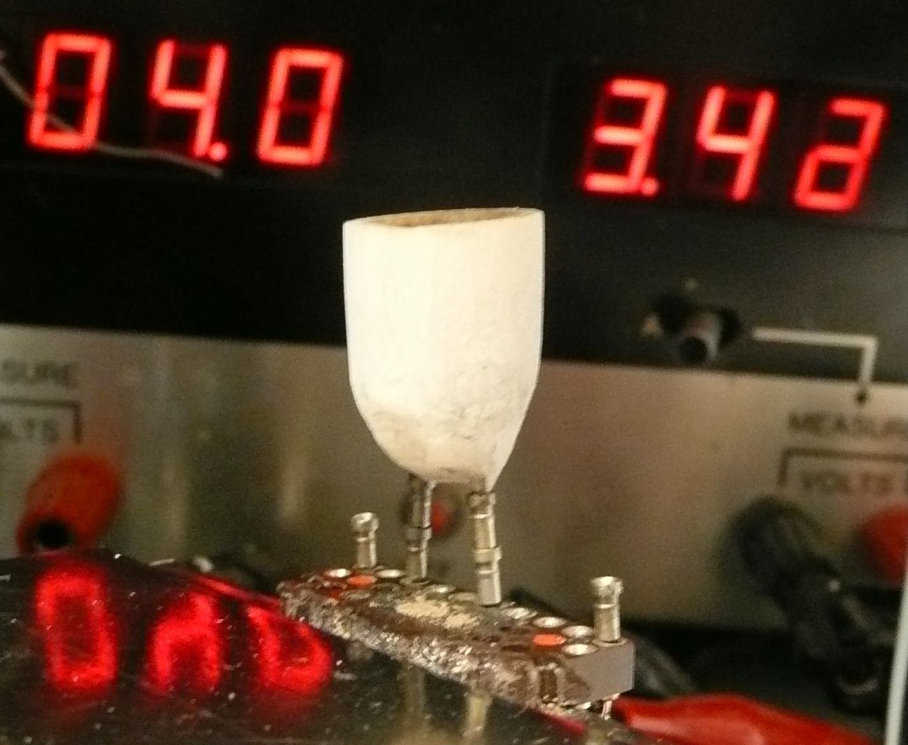
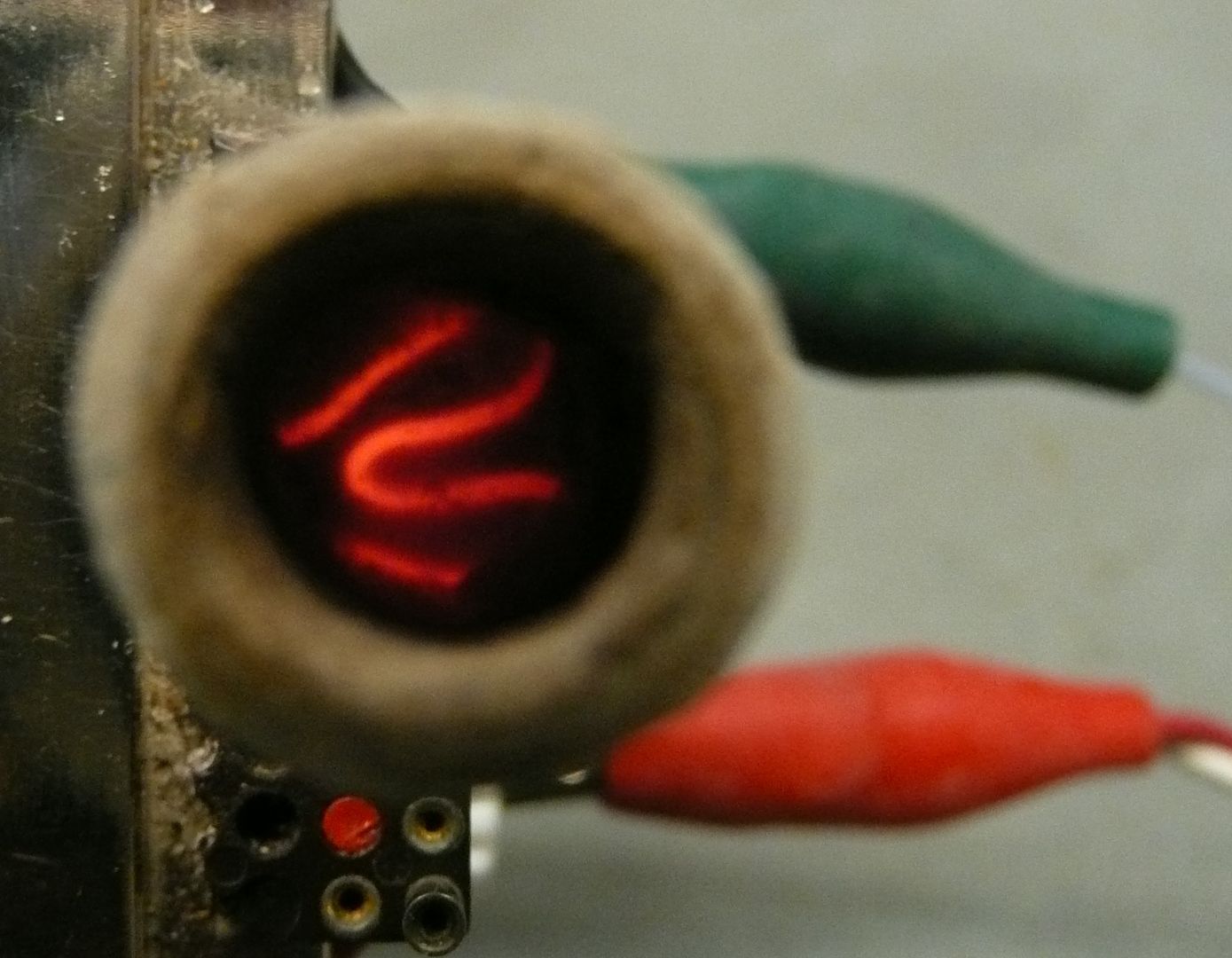
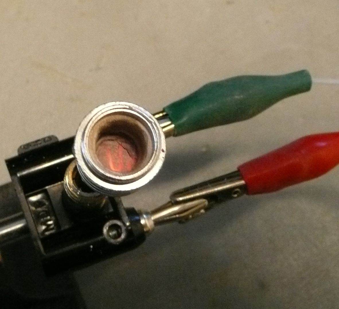
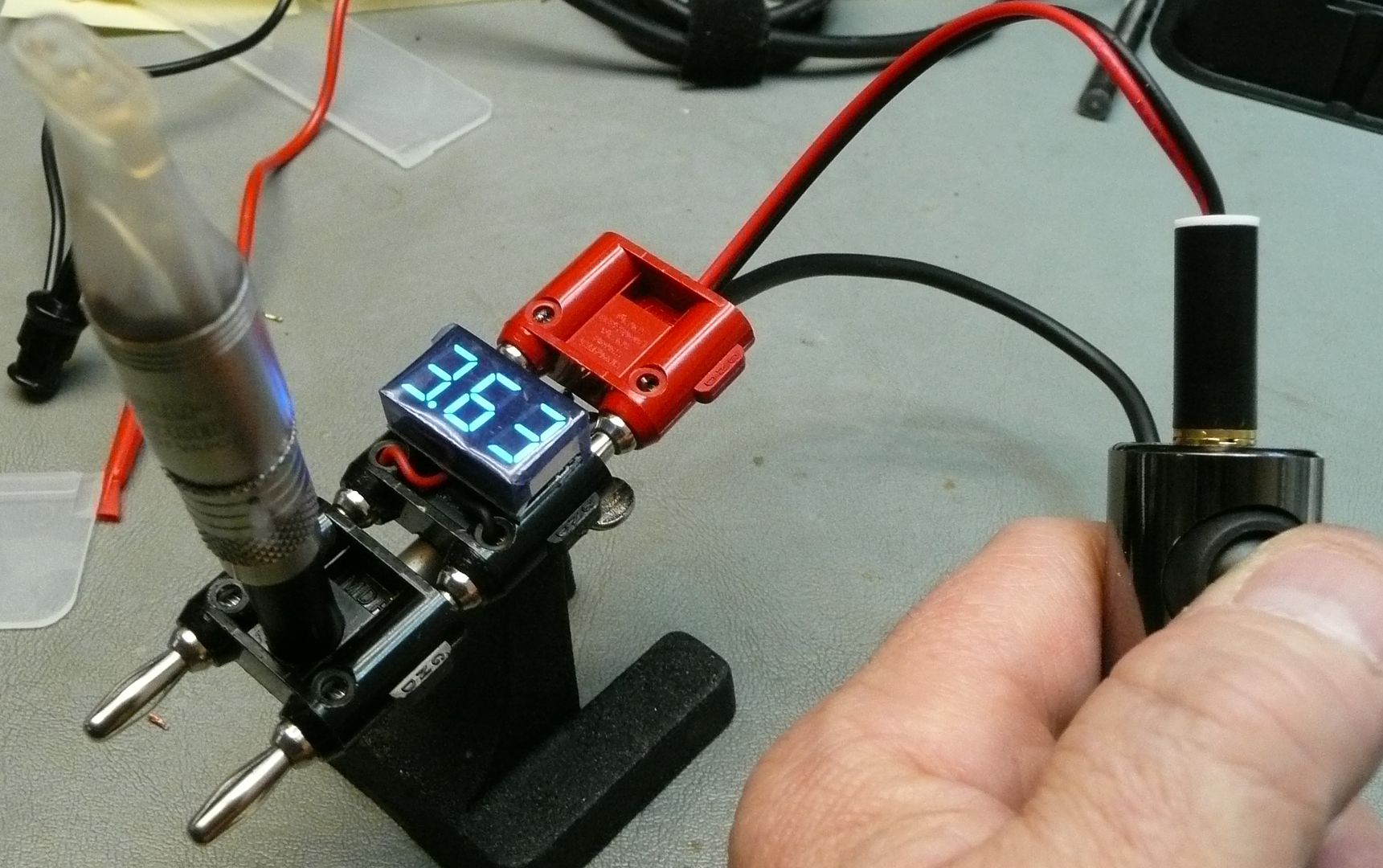
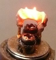
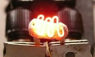
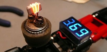
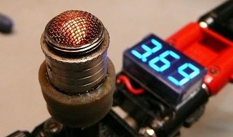
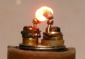
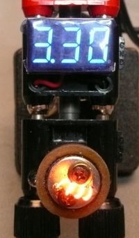
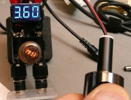
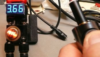
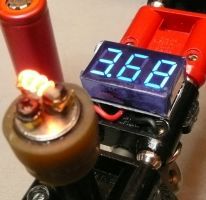
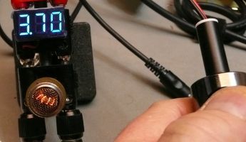
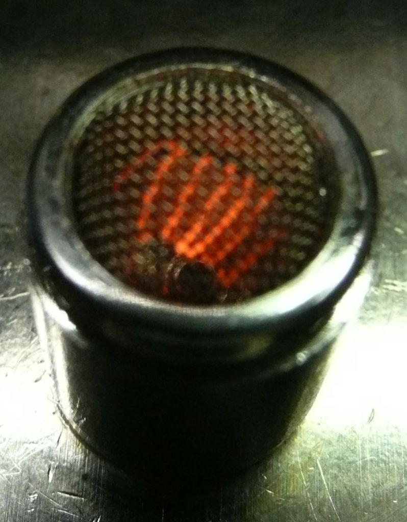
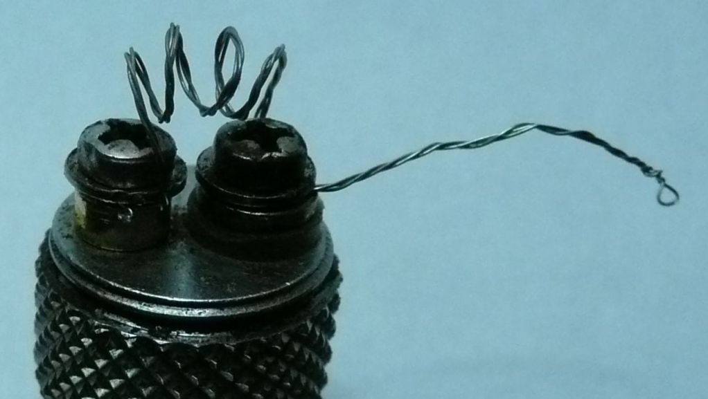
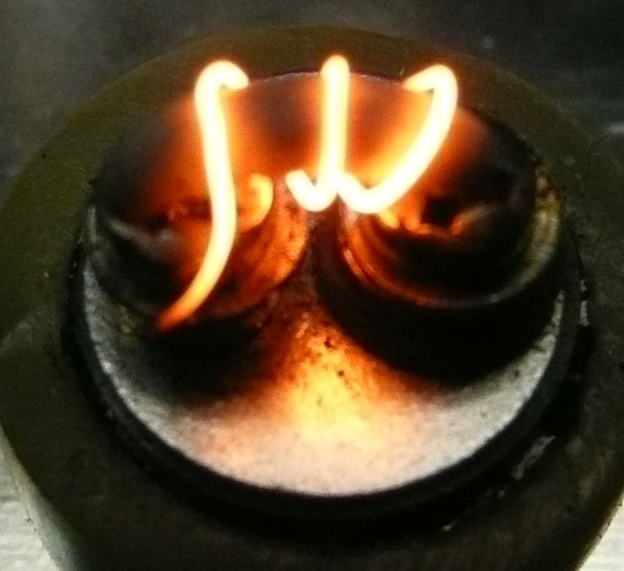
Here is the result which is pretty much the same as the Bulli.
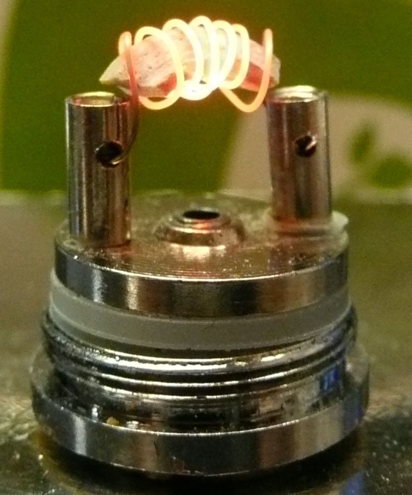
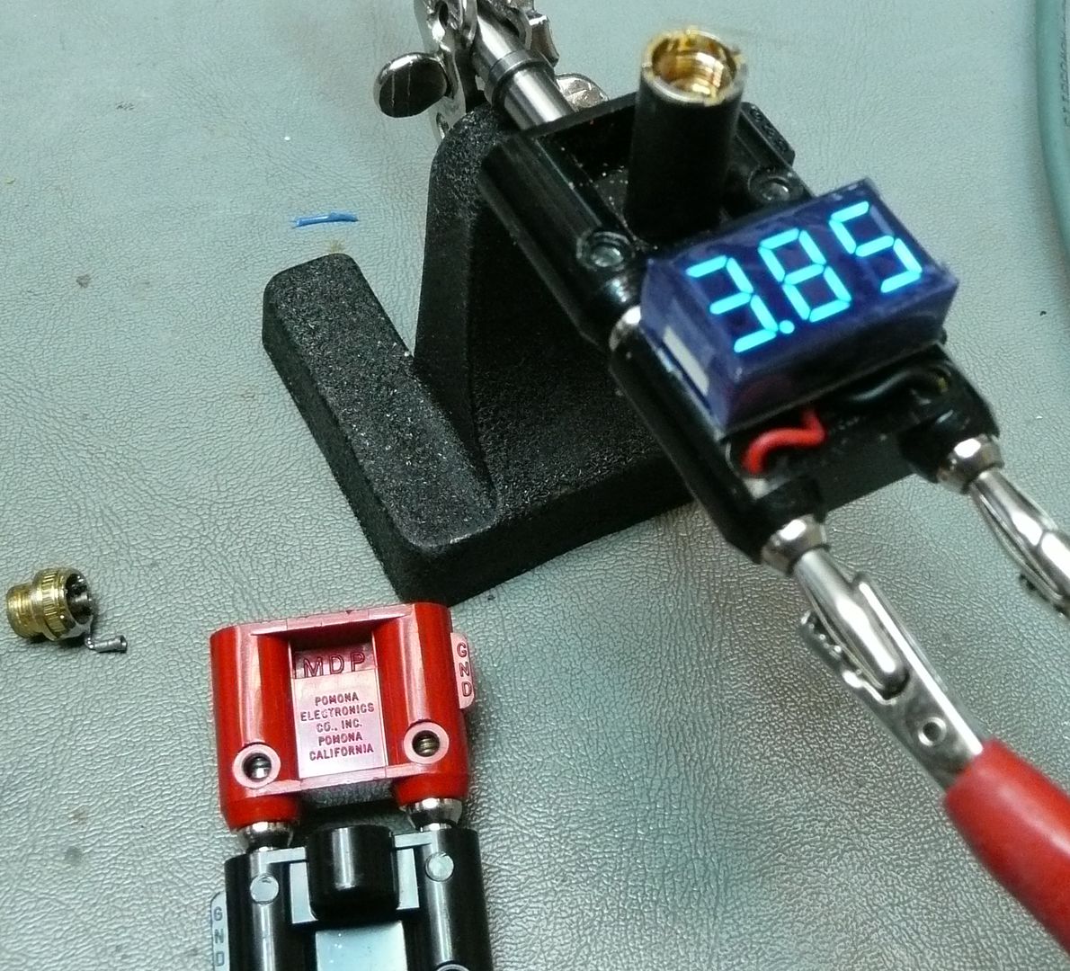
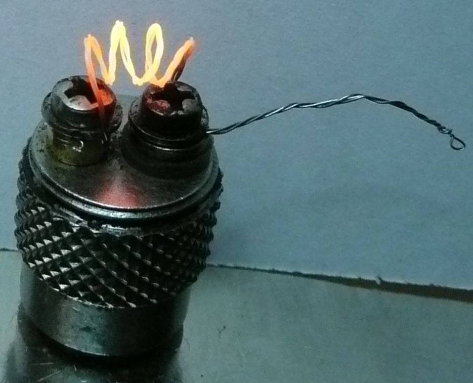
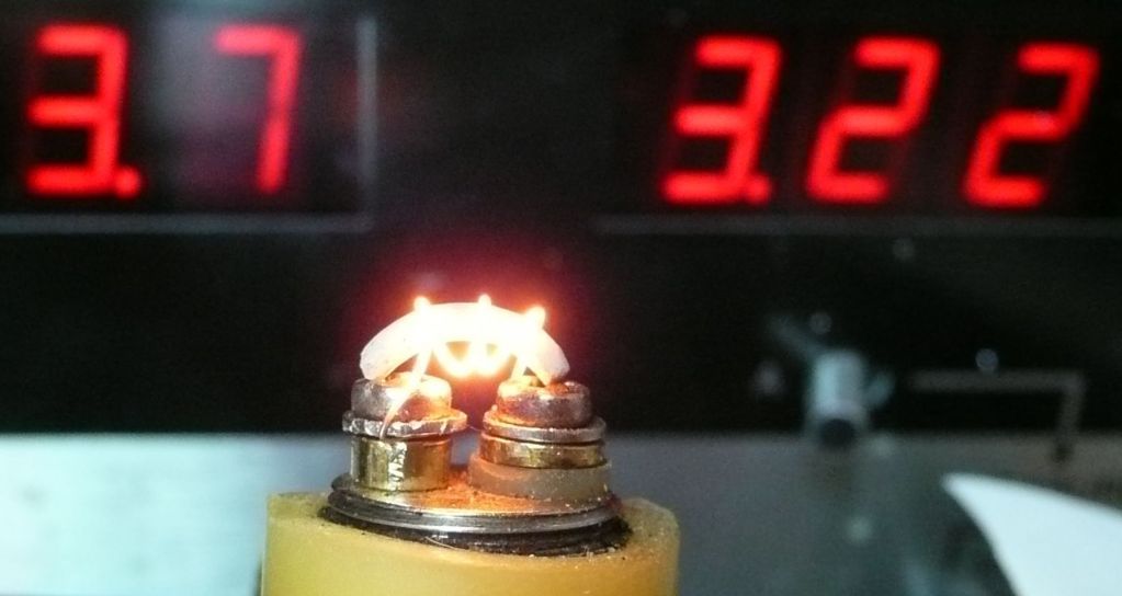
So in practice it does perform much like the bulli. I did have issues with shorts from ground post shorting out to the positive power plate. This came about while prolong heat bench testing. The solution was to adjust post so had clearance and no pressure against side teflon insulator. IMO, not a permanent solution as makes too easy for short circuit. Might try making the hole larger in positive plate. ?
The biggest issue which is very different is the heat transfer back to the power handle is much more. I noticed big time as I use my little power handles and they get too hot to use for a quick session with this unit. Can still use if wait a bit between hits. With the Bulli it gets hot but still usable.
I have given a unit to my co-worker for testing. I am really bad at not knowing much taste differences, but he seems to.
The Pros.
-Cost effective
The Cons.
-it's very cheap material and will not last. The 510 connector will likely chip first time drop.
-reliability issues with ground pin pass through
-fast heat build up
Overall opinion, Basically you get what you pay for. This clone does perform but just feels cheap and have doubts as to longevity. Time will tell.
I will keep the testing going with this guy and keep this thread informed. IMHO, this Clone unit (UFO) is not worth pursuing at this point if thinking of ordering.
Pipes
I have started using the one piece ego drip tip. I like the one piece because it's easier to remove while unit still hot. The two piece wants to separate at the 510 tip. Save some coin as well. Many out there, just google "ego drip tip type b".
Also, the single coil element IMO is the way to go. 30 AWG Kanthal type A. For 6 volt 3 ohms or 4.5 inches seems good.
NEW CHEAP ALTERNATIVE:
I was searching around the web and found China has started making Bulli Clones and caught my eye.
The main thing which really got my interest was the price. Under $5 a unit with the catch being minimum quantities. I would imagine soon to be available in local ecig shops.
Well had to take check them out. I ordered a test sample pack to experiment with.
They come pre-coiled with a 3.5 ohm element. The center plate with puncher pin un-screws rather than pressure fit.
The size of that puncher pin is crazy. The tank does not come with a cap. I thought that was odd as is the only thing missing besides the ejuice and battery to get it up and going for ejuice users.
Right away I ran into a noticeable problem.
The skirt is not removeable. Dam, I thought it was as I discovered there are more than one type of clone. Anyway, have to work with what I got.
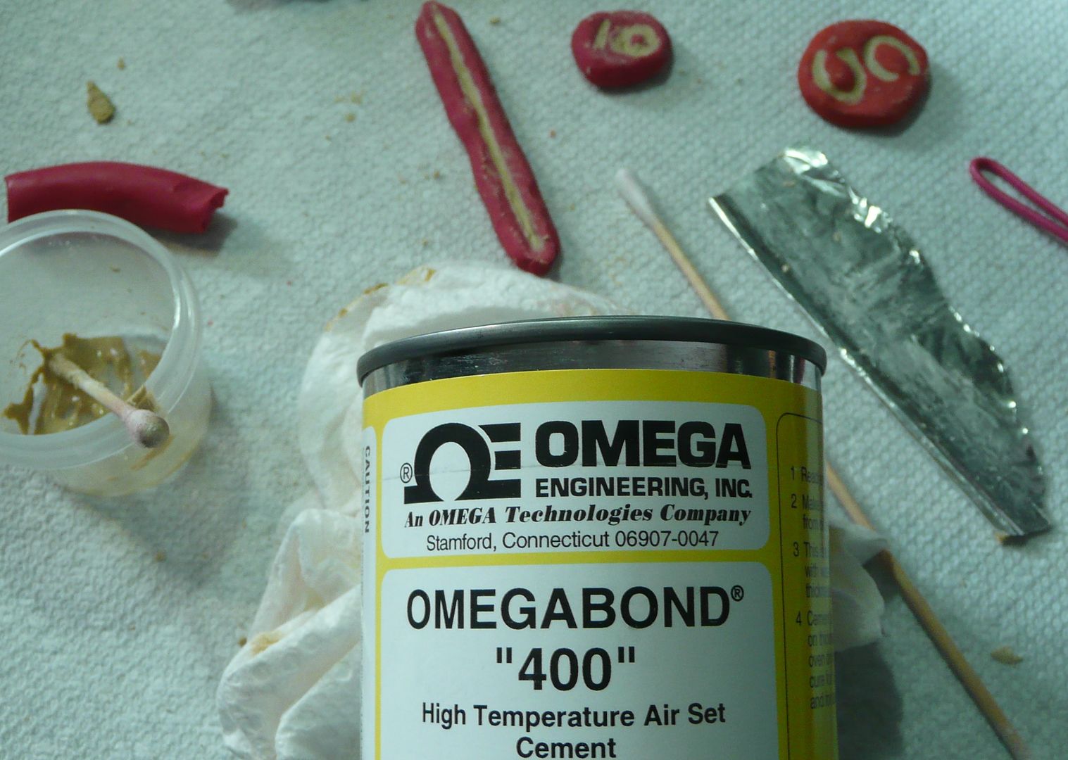
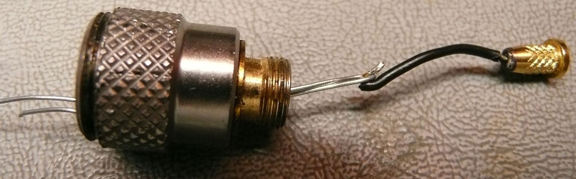
My first impression was that these things are cheap, cheap, cheaply made. Material is that brassy looking stuff and is brittle as hell. At least this made it easy to break away that skirt. Now as for the actually design, I have to admit it's very clever how they put it together. Of course the first thing I did was sacrifice a unit to see how it's put together.
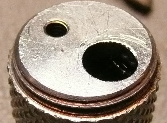
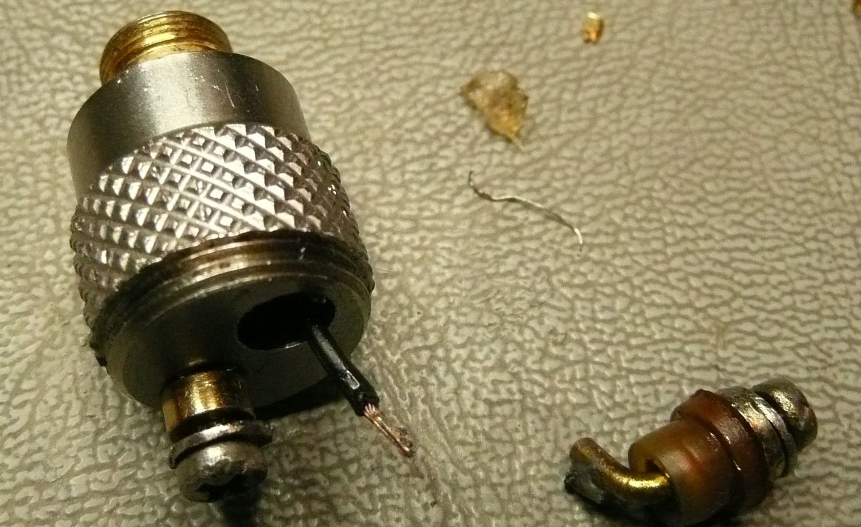
A big electrical difference is the center pin of the 510 connector is threaded into a circular plate which has the positive post mounted on it. This is the complete positive side of the circuit. The ground pin is screwed through a hole in this disc with a thin piece of silicone insulator. This is one of the weak points of the design. The method they use to attach the heating wire is using very small screws which go down the posts and press the element via small holes in the side of posts. These are very flimsy the philips head strips very easily. A proper fit screw driver is a must here. I do not think this unit would hold up well for multiple rebuilding. But for once or twice......
Air path is also quite different. This unit draws air up through the center pin as to support automatic batteries I guess. At first I was a little disappointed as again like with the skirt I thought I saw holes in the pictures. Must have been a different clone. There is another one called the "Bully" spelled different. I think that this the one with holes and removable skirt. Anyway, the holes on the sides of the 510 threaded piece IMO were too small. I drilled them to 1/16" and seems OK. I left the single hole in the center alone.
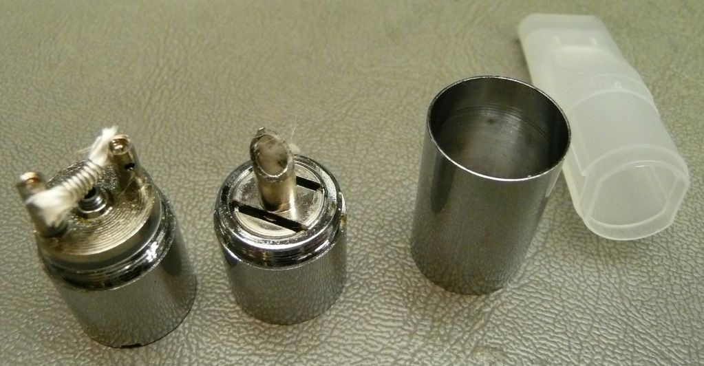
Unit overall mass is much less and the actual base is about 3 mm shorter with skirt removed. Causes heat differences.
The rest of the mod is pretty much the same as with the original Bulli TM mod. The center portion screen hole part is a little smaller and threaded instead of a rim grooved like the Bulli. The juice tank piercing spike plate is removed by unscrewing it instead of popping out.
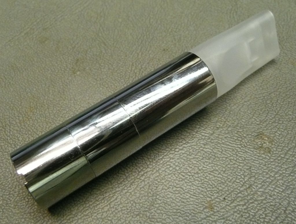
Here is the result which is pretty much the same as the Bulli.
So in practice it does perform much like the bulli. I did have issues with shorts from ground post shorting out to the positive power plate. This came about while prolong heat bench testing. The solution was to adjust post so had clearance and no pressure against side teflon insulator. IMO, not a permanent solution as makes too easy for short circuit. Might try making the hole larger in positive plate. ?
The biggest issue which is very different is the heat transfer back to the power handle is much more. I noticed big time as I use my little power handles and they get too hot to use for a quick session with this unit. Can still use if wait a bit between hits. With the Bulli it gets hot but still usable.
I have given a unit to my co-worker for testing. I am really bad at not knowing much taste differences, but he seems to.
The Pros.
-Cost effective
The Cons.
-it's very cheap material and will not last. The 510 connector will likely chip first time drop.
-reliability issues with ground pin pass through
-fast heat build up
Overall opinion, Basically you get what you pay for. This clone does perform but just feels cheap and have doubts as to longevity. Time will tell.
I will keep the testing going with this guy and keep this thread informed. IMHO, this Clone unit (UFO) is not worth pursuing at this point if thinking of ordering.
Pipes

 Keep it up!
")


") Impressive indeed keep tinkering!
Impressive indeed keep tinkering!