Zion Power Adapter (transform your Zion into a desktop vape)

KeroZen

Chronic vapaholic
WARNING / DISCLAIMER:
1) When dealing with electrical devices connected to the mains, there is a serious risk of death or injury. Please be careful and use your common sense. Always work with the power cord unplugged.
2) To reduce the risk of fire in case of unexpected failure, always unplug the PSU when you are not using it and when you are leaving home.
3) Having your Zion tethered will increase the risk of damaging it if someone trips on the cable. If you are lucky the adapter should unplug, but otherwise it can make your Zion fly in the room and you will likely break the internal glass parts if it happens.
4) Even if the output voltage is quite low, the amps are relatively high and could cause some shock or injury. So be careful when touching the exposed contacts on the adapter side too.
5) In short: use your brain and don't hold me responsible if you screw up!


Introduction
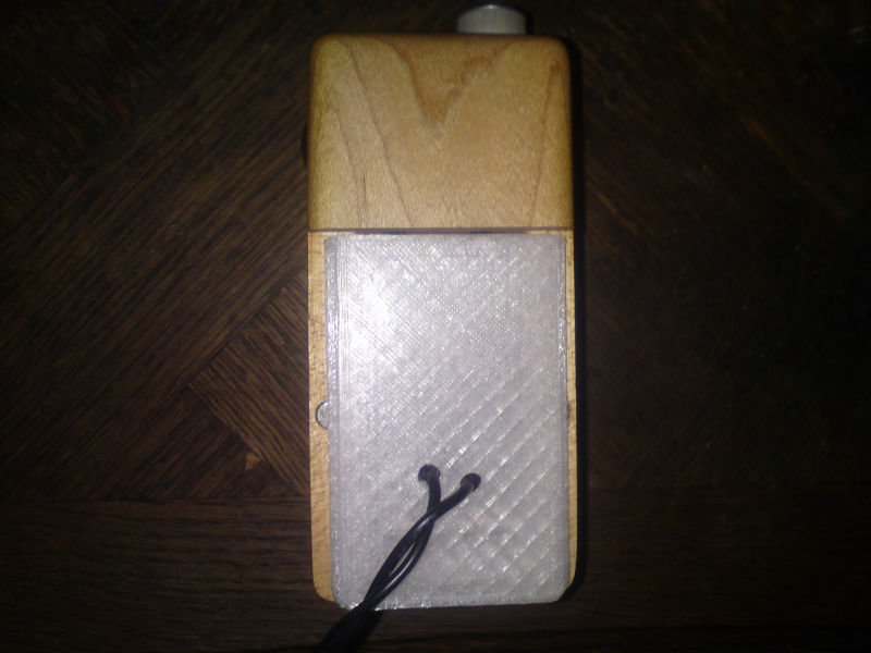
I will try to produce a step by step guide to create a Zion Power Adapter (ZPA) from scratch using cheap parts easily available. I currently have a fully working prototype that I've been enjoying at home, but it's not ready for prime time yet (mind you, the kid is a bit ugly...)

I could wait for its completion and show you only the end result but then this guide would be very short and not super instructive. I think it's best to show you the progression and the various iterations. Plus if I don't post it now, there's a risk I will forget the details... so let's get to it while it's still hot!

This will by no means be complicated and apart from basic soldering (unless you use an alternative for that specific part, more on that later) you won't need any skill at all. If you want to use wood for the door on the other hand, then it will be more involved (unless you manage to hobo Ryan to make him sell you a pre-made door... or if you sacrifice your existing door but I don't recommend that)


Pros
- Turns your Zion into a desktop, in a non permanent fashion (can always revert to batteries)
- No battery voltage to monitor anymore, no cells to swap and charge
- Unlimited autonomy
- Zion will be lighter to hold, adapter weights less than two cells

Cons
- Tether limits your motion range, can be annoying when passing around in group settings
- Serious risk of tripping on the wire and damaging your Zion in the process
 
Last edited:

KeroZen

Chronic vapaholic
Required Tools
So we are keeping it low cost and easy by design. There is a single tool that you will need: a voltmeter. You could even complete the full project without using one, but that would be a bit of "the leap of faith"! Indeed, the chip inside the Zion is quite sensitive to both reverse polarity and over-voltage.

KLAVbBl.png


If you don't own one already, a cheap ~$5 job like the one pictured above will do the trick (we'll only be measuring low DC voltage) but please don't even think about using it to measure anything connected to the mains (i.e. the wall outlet) this is only to measure the circuit between the PSU and the Zion.

Instead of buying one, also consider asking around you if you could borrow one from your friends or family. No need to buy a tool if you only intend to use it once. Otherwise for the most non-tech-savvy readers: a "digital multimeter" is what you want, it includes a voltmeter function.


Optional Tools
In the current prototype form, you will need a soldering iron. It might be possible to use another kind of connection (I'm thinking about crimping at the moment) in which case this tool would not be needed... so it's optional in theory but currently required! :p

wdjWCPV.png


Again any cheap job would do the trick, what we need it for is the most basic operation one could imagine, requiring no real precision nor precise temperature.

I do recommend getting at least a cheap Chinese regulated iron like on the picture, it was around $30 shipped and is compatible with Hakko tips. If you can afford a genuine Hakko, then good for you! (they make good stuff) But temperature regulation will make your life easier. Again no big deal if you don't intend to use the tool often, even the cheapest iron you can find will do.

You'll also need some solder, whatever the type. A thick wire with flux like this "German quality" stuff would do:

6gr12vH.png


Make sure it's for "electronics", and lead or lead-free is up to you. Lead solder is easier to work with though.

Lastly you might want to use a pair of cable stripper pliers:

d2ihQHA.png


This Chinese one costed me about $3 shipped. You can use scissors or a knife to perform the same task but it's cleaner with those.

That's all we need for now!
 

Abysmal Vapor

Supersniffer 2000 - robot fart detection device
Interesting .Is this based on a led power supply like the PA for TUBO that FJ introduced us some time ago in his thread ? I have one in the making but havent really finished yet,just got back from a vacation and will get on it once i gather my DIY powers,so i will be watching this thread with interest.
Alternatively i have thought it could be done with universal laptop power supply and dc voltage controller like those on the logvapes ,but i have to find one that can handle nice amperage.
 

KeroZen

Chronic vapaholic
The Power Supply Unit (PSU)
The core component of our project is the power supply. Technically what we need is an AC/DC converter of some kind, with an output voltage falling into the specified range of the Zion brain, as well as supporting a current high enough for the Zion heater.

We could build such a device from scratch, that would be a fun project but it's completely out of the scope of this guide! So instead we'll get a ready made unit and that will be the major cost of our project. You can expect between $15 and $30 shipped for this part alone (or way more if you get some kind of deluxe unit)

There are many possibilities here including but not limited to:
- Re-purposed computer (PC) PSU
- LED driver PSU
- Laptop wall adapters
- Generic fixed voltage PSU meant for something else

Like for most electronic parts, it's cheaper to get them from China. I got mine from aliexpress but the listing is gone already. I went the led driver way as I found one that looked spot on. You can get them also on dhgate, banggood and all the usual suspects.

The keywords are: "led driver", "power supply", "ac dc converter". The requirements are as follows:
- make sure it supports your country voltage (110V vs 230V) some can be switched some can't
- make sure if it has an integrated cord that it matches your wall plug format
- you want a "constant voltage" PSU, not a "constant current" (beware some LED drivers are CC and not CV, if unsure ask the seller but most cheap ones are CV anyway)
- a power rating of 100-150W will give you peace of mind and is not necessarily much pricier
- the output voltage must be between 7V and 14V, fixed or variable doesn't matter (7.5V to 12V is optimal, if you select 14V make sure it's not exceeding that value or you could damage your Zion)
- the output current must be 10A minimum but 15A or 20A is better and again not really pricier

Here are a few BangGood links which I hope would be more durable than random sellers on aliexpress, but they are not necessarily the cheapest. Some are on sale now and are interesting. All these units would work:

12V 10A Laptop style PSU (rugged and more compact, recommended) - https://www.banggood.com/Charsoon-1...Adapter-Switching-Power-Supply-p-1147700.html
12V 10A mini LED driver (cheapest) - https://www.banggood.com/Mini-120W-...to-12V-10A-for-LED-Strip-Light-p-1019136.html
Anet 12V 20A - https://www.banggood.com/12V-20A-24...ower-Monitoring-For-3D-Printer-p-1108988.html
Mini PSU 12V 20A (220V only) - https://www.banggood.com/Mini-Switc...V-20A-250W-For-LED-Strip-Light-p-1017261.html
Generic 12V 10A/20A PSU - https://www.banggood.com/AC110-220V...-Switching-Power-Supply-Module-p-1162235.html
12V 20A LED driver (220V only) - https://www.banggood.com/AC-220V-To...er-Driver-For-Strip-Light-Lamp-p-1145388.html
12V 20A Car converter PSU - https://www.banggood.com/240W-AC-10...ansformer-Power-Supply-Adapter-p-1108341.html
12V 20A LED driver - https://www.banggood.com/240W-110-2...ing-Power-Supply-For-Strip-Light-p-73834.html


8iyorjQ.png


This is what I went with. It's a 150W 7.5V 20A single output switching LED driver PSU. Voltage is somewhat configurable but 7.5V is perfect and the Zion already has a power knob anyway.

This unit is clearly built down to a price. I paid $22 shipped back then. Components inside are low cost, cheapest capacitors they could find (will probably not last more than 10 years!) It's a phenolic board like in most of these cheap units (you can recognize it by the yellow color of the PCB)

Un9Ep6b.png


When seen from the side you can notice that the board is bent inside. This is due to not enough clearance above the main transformer, it's pushed down by the top grill and applies pressure on the board. Clearly not a big fan of that, but hey you get what you pay for!

L1zJI5s.png


Some units auto-switch between 110V and 230V, this one doesn't. You need to manually set a switch poking through the grill with a plastic pen or the like. If yours is like that don't forget to check that it's set to the correct voltage before first use, otherwise poof!

Lastly the page claimed it has all kinds of protections, like over-current, over-temp, etc. I honestly don't trust generic low-cost Chinese stuff and so I just assume it's not there (who knows how they did it, might work or not, might be a one off protection then it's gone... better not take the chance anyway)

PS: the unit is not as big as it looks like and if you get a laptop style one it's even more compact
 
Last edited:

KeroZen

Chronic vapaholic
The Wall Plug Connector
If your PSU already comes with a cord and plug of some kind, you can skip this whole section. Otherwise, you will need to build one. I took a standard supply cable for PC's and the like as there are everywhere and I have way too many:

5BnZnoc.png


If you don't have one, again ask around as they are very common. Any other cable would do as long as it has a plug compatible with your country standard.

Cut the cable *with the cord obviously not connected* close to the end that normally goes into the PC (and yes I did not specify that you required scissors in the tools section as I assume you have some!)

Then use the stripping pliers to remove the sheath and expose the three wires:

TynoE1V.png


Then using a screwdriver (type will depend on your PSU) connect the wires to the PSU as follows:

aarDHXl.png


Brown goes to L for "line", blue goes to N for "neutral" and green/yellow goes to "ground" (or the symbol like here) If your cable has a different color coding, please refer to online charts to know which is which.

Tighten the screws relatively hard, you really don't want those wires to unplug and flap around in the breeze, that would be a real hazard!

In the same vein, the last step I did was to create a strong strain relief on the cable, so it would be nearly impossible to rip it apart if ever someone tripped on it:

9O8hcE3.png


I used a pair of pliers and cable ties and made a rough S shape with the cord, taking advantages of the presence of the top grill.

Alright, we're done with this part!
 
Last edited:

KeroZen

Chronic vapaholic
Building the Prototype Adapter - 1 The Plan
Now that we are done with the trivial part, we need to tackle the adapter that will replace the Zion door and batteries. Here's the plan:

- A first prototype will be designed and 3D printed, as a proof of concept
- A refined prototype will be designed and 3D printed
- Then eventually (depending on Ryan's good will?) the final idea would be to have the door part made of wood, and the remaining of the adapter 3D printed as one piece and fastened to the door

I will publish the files at some point such that you can print them yourself or use any print-on-demand commercial service to have the part printed and sent to you.

I don't think I have the skills to produce wooden doors like that, perhaps my friend could... but ideally it would be best to get original doors straight from Ryan. This is also why I was disappointed when he told me he scrapped all the old doors when he switched to the new width...

By the way this new width will be problematic, as I can only test on the old one. I will need one of you to measure it as well as the edge radius on a recent Zion model. We will likely end up with two sets of files.
 

KeroZen

Chronic vapaholic
Building the Prototype Adapter - 2 The Ugly Kid
This part will be full of "do as I say, not as I did!", because that's what prototypes are for isn't it? And as you will see... well, don't be too critical! :p

I forgot to take a picture of the naked 3DP part, but it's quite basic at the moment: a replica of the Zion door, one profiled wall to grab on the bottom copper contacts of the device, and a top profiled wall to hold our own contacts in place, just in front of the Zion springy ones.

It was printed with PET, the same plastic as in clear water bottles. For no particular reason, just because that's what my friend was testing at the moment and it was loaded in the printer already. The crystalline aspect is not the best match with the Zion wood, I must confess... but otherwise the material has nice properties so it seems.

For the contacts I took two long 5mm diameter screws with flat tips. I have strictly no idea how much it makes in your savage imperial units, but we'll have to sort it out at some point if we want the files to be compatible with what you have (note that currently the idea is to print holes too small on purpose and have the final user enlarge them to the right size by screwing in the actual screws)

irRo6yF.png


I'll give you the required length later, but this can be compensated and/or adjusted in the next step to accommodate what you are using. But first you need to use a file to flatten and smooth the tips of the two screws to improve the contact surface.

Then, and this might be removed in the future, although it appears to work well, you will need a piece of cork. For me it was Champagne, please!

nPLCdSR.png


I cut a fine slice, a few millimeters thick, then took the central band and spared the other parts. The cork is a cheap way to have our contacts "springy" and allows some play and adjustment of the pressure force.

Here's a mockup of the adapter, the contacts and the cork bit:

853pNaj.png


Of course having two free floating contacts non isolated like that is a disaster waiting to happen. So when I glued the cork piece in place, I also cut the remaining bits to create some physical isolation that would prevent any short in case one the contact moved. This will be addressed in the second prototype.

12Ks2I8.png


As you can see, I also hand drilled two holes to pass the wires but they are offset... I told you the kid would be ugly!! Again, clean holes with tapered exits as to not damage the wires will be added in next iteration.

Talking about the wires, I would recommend between 1 and 2 meters (times two, one for + one for -) of 14awg multi-strand wire, if possible with silicone sleeve. I had not enough at hand so I used 16awg with old-school PVC sleeve (do as I said not as I did!) it works well, no voltage drop, no noticeable temperature change, just not as smooth as the silicone ones and a bit too thin looking.

Strip the insulation on the ends and perform the so-called "underwriter's knot" as in the following picture (worth a thousand words, especially when explaining how to tie knots)

ZtRwuSi.png


This will provide strain relief and prevent the wires from being ripped off. But don't tighten the knot at this point, just evaluate how much wire length you will need, then slide the plastic adapter away for the next part (thermoplastics don't like heat)

Alright, this is where things went wrong! It was a bit dark when I selected the two screws for the contacts...and they looked like brass to me... hm it turned out they are not at all, possibly stainless steel instead with some kind of coating or plating, I don't know. Long story short: impossible to solder the damn wires to them. The solder just didn't want to flow on the screws at all...

So plan B, I used a fine pure copper wire to roll around the screws and fasten the wires tightly, then I secured the copper wire with a blob of solder. Yeah, this is a bit how ya doin', to use that Australian expression! :p

AmoyZIF.png


For next version, the idea would be to crimp the wires between two 5mm nuts, removing the soldering iron requirement.

I installed the contacts in place, tightened the knot then proceeded to attach the other end to the PSU. This is when I triple checked the polarity using the continuity mode of my meter. When the door of the adapter is facing you, the left contact must be positive and the right negative. Swap the wires on the PSU side otherwise.

ZsEQ3LJ.png


I also checked the voltage both at the PSU side and at the adapter contacts. Couldn't measure any voltage drop. As well as during actual use, the voltage on this PSU doesn't bulge. Make sure to put back the plastic protective cover on the PSU terminals, they should not stay exposed for safety reasons.

WSsaMUc.png


Ah and did I tell you that my friend screwed the measurements of the door and the print is not wide enough?! That's what happens when you use the Zion before getting to work! :p

yUtHzoe.png

mFAAZjh.png


This has been fixed in the next iteration amongst other things. We re-worked the model today but due to the heat wave we currently have over here, the printer jammed and the print failed. So you will have to wait for the next episode!
 
Last edited:

funkyjunky

www.lamart.ch
Manufacturer
hey kerozen!

great tutorial!

please be super catious when having the psu open like this and having it connected to main voltage!

IF YOU TOUCH THE OPEN SCREW TERMINALS WHERE MAIN VOLTAGE COME IN YOU WILL BE SHOCKED HARD!

this is really a dangerous situation!

i advice anyone to encase the psu in a box as soon as they start working with it.

if you give me the proper dimensions (maybe make it slihtly loger so some cable can fit as well) i can offer to cut a box with the laser cutter, could send the sides in a flat envelope to diy.

edit: i see you mentioned this quickly
 

KeroZen

Chronic vapaholic
Yes thank you for emphasizing that aspect! I briefly mentioned it but as I didn't want to sound too patronizing maybe I didn't make it clear enough: the protective plastic cover on the terminals must be on at all times, it's not an option.

But even with it in place, this kind of setup is not really user friendly. These LED drivers are after-all meant to be installed once and hidden from view, not something you are supposed to have laying on your floor exposed to all kinds of possible troubles...

This is why the laptop style bricks are a better choice I think: everything is contained, it's pre-wired, it's sealed etc. You just need to strip the jack connector on the output end. It's just harder to source one with the correct amp rating.

PS: I'll drop you a PM for your box offer, thank you very much!
 

KeroZen

Chronic vapaholic
Thanks mate, I really appreciate!

Next step will be testing the second FDM print (black PLA), validating it. Then modeling the thicker version to accommodate the new door style (this one I will not be able to test myself)

If the test with the PLA shown in previous post is a good fit, I'll try to have it printed in resin with a SLA machine and I'll probably use that for myself.

I will then post 3 files here for you to print or get printed: thick vs thin doors and one without the fake door to screw on a real wooden door.
 

virtualpurple

Well-Known Member
Is there anyone in the US with the tools and know-how willing to be hired out for this? I would love one but don't trust myself to build. If anyone is interested let's chat!
 
virtualpurple,
Top Bottom