-
SCAM WARNING! See how this scam works in Classifieds.
You are using an out of date browser. It may not display this or other websites correctly.
You should upgrade or use an alternative browser.
You should upgrade or use an alternative browser.
VapCap Induction Heater for Desktop and in Car Use
- Thread starter Pipes
- Start date
-
- Tags
- dynavap induction heat vapcap
Archaicrevival
Well-Known Member
I'm sorry I didn't know about this thread... Would this work/help?
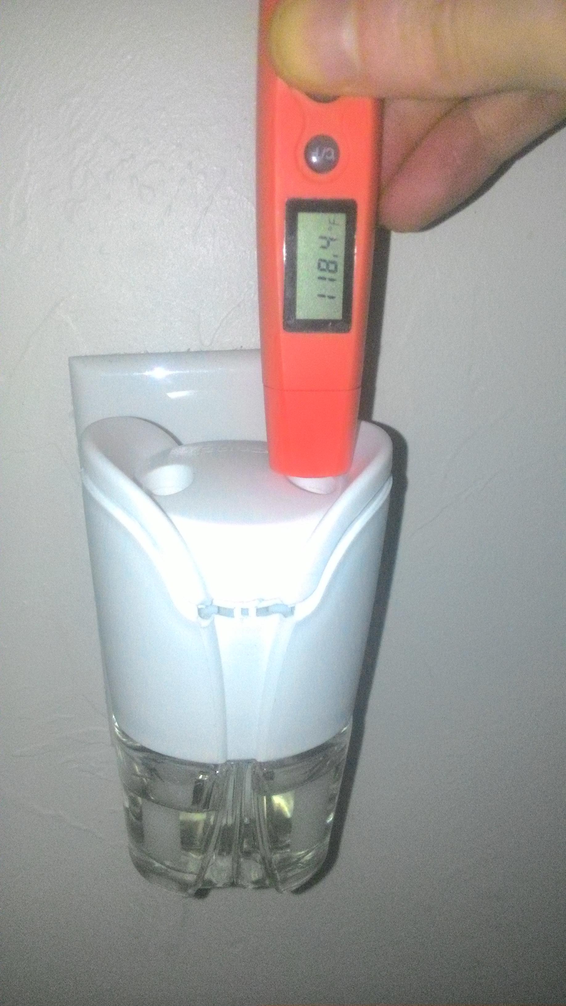
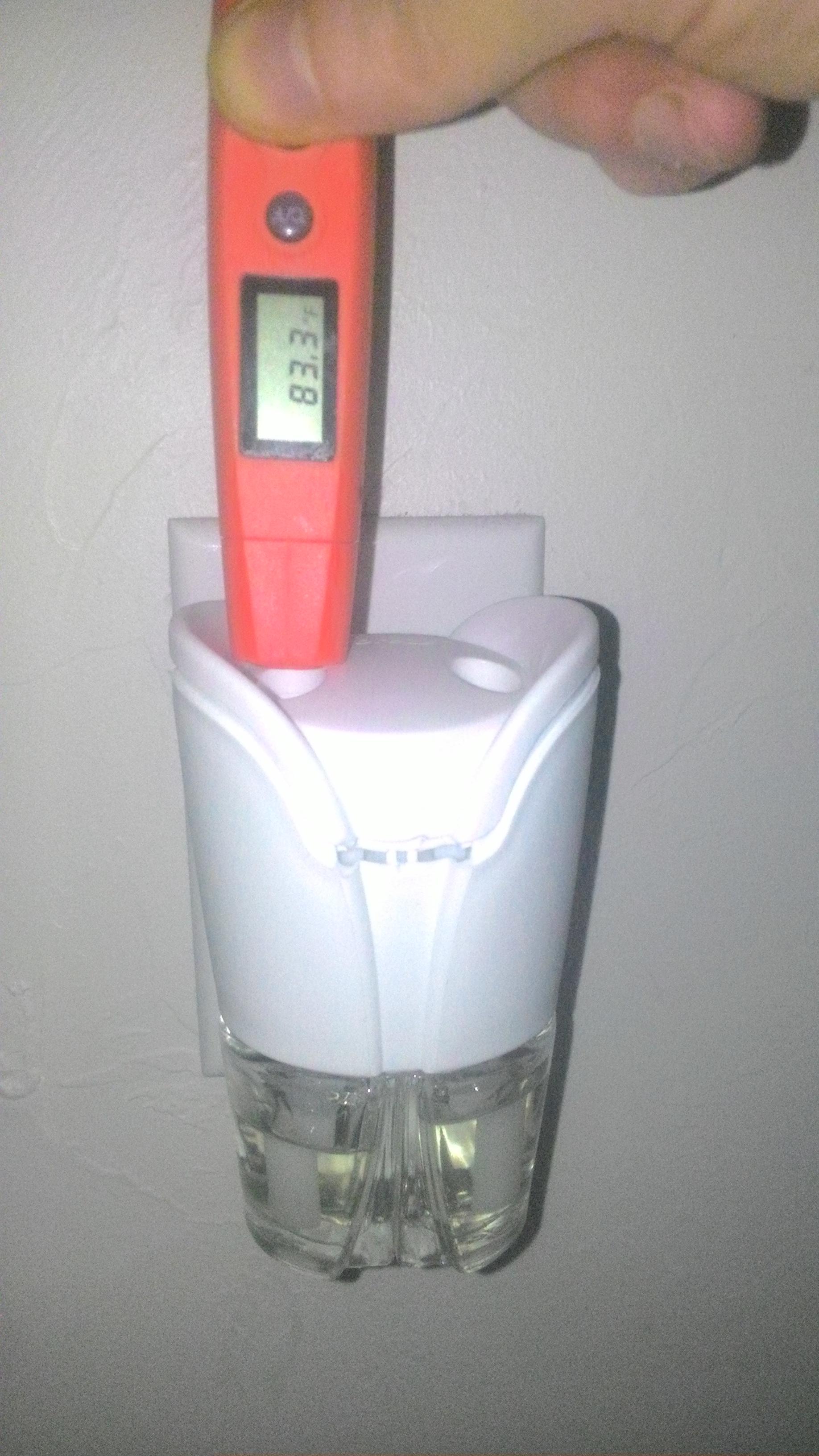
I don't know too much about electronics yet but it seems this with some mods this should heat the vapcap? The hole is slightly too small and it didn't get hot enough (though I didn't leave it on long) The right side got to 105F. Seems to get up to 135F on one side. There is a low/high setting ... It's one of those glade plug ins, I was bored :/
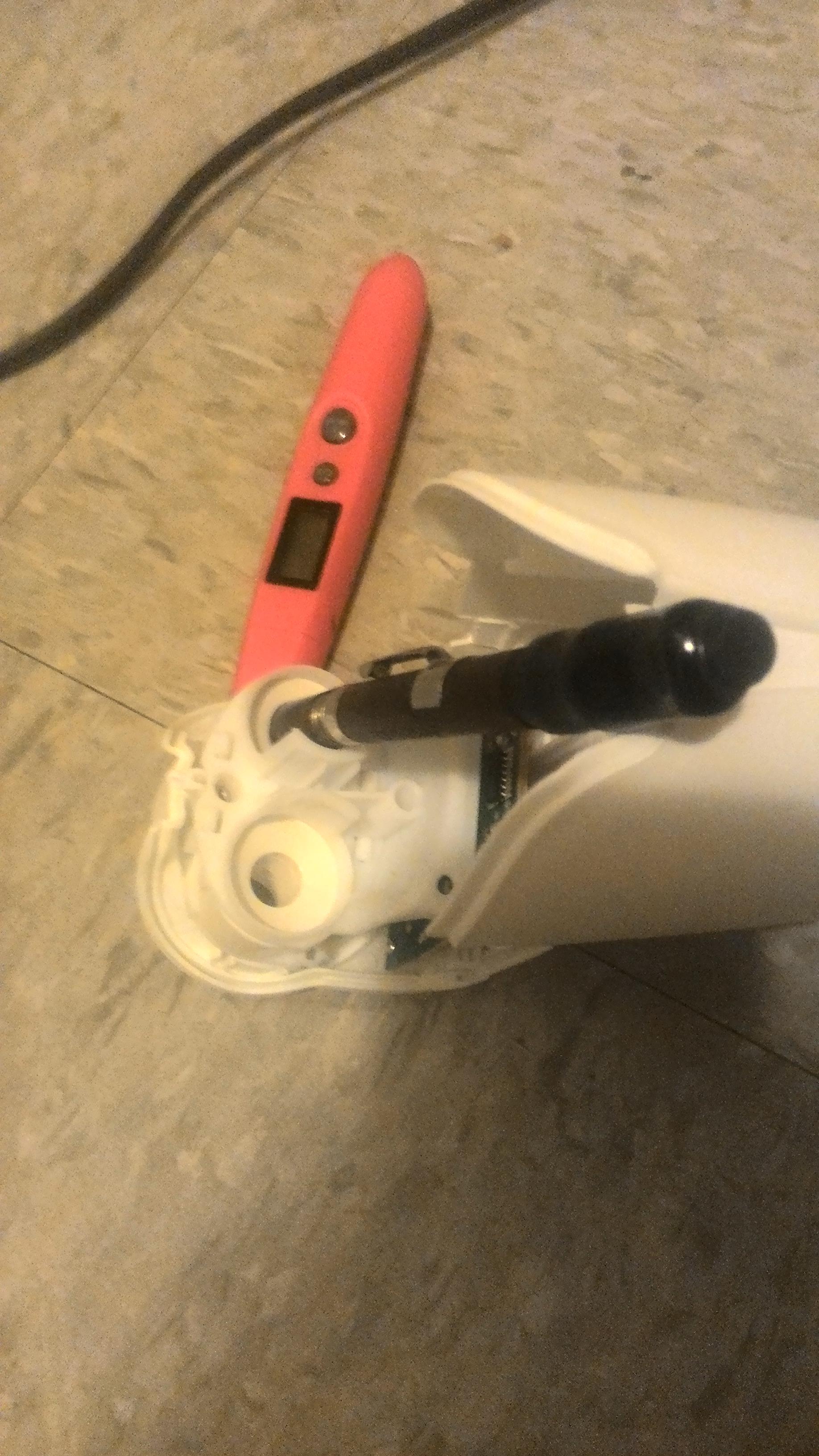
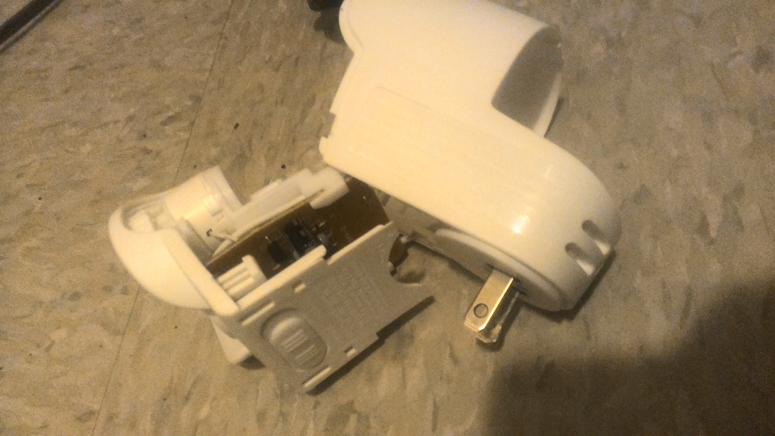
And this I'm confused about, why more liquid gone from the side with less heat?
Now that's the kind of "out of the box" thinking that can get one's ideas flowing. But I don't think it's functional in our case as the heat is only making oils very warm to speed up evaporation. Fun thought though.
So guy's, where to start. First off, my apologies, for what has turned out to be a prime example of chasing a wild goose. I'd like to back up to before I had the testing in the car fiasco. That happened at the same time I was getting reports of some power supply hiccups as we were pushing the threshold of ratings. This is where I went off trick with experimenting with double looping and thinner AWG wire in an attempt to cut down on current output.
Let's forget all the 16 AWG stuff altogether as the best solution right in front of our noses. Multiple looping was working because of, what I believe, was detuning the tuned circuit and or the mentioned self heating.
Moving forward.
100% back on track and no messing with anything but the stock coil. I figure the coil is already tuned for maximized power and therefore left alone. The key is in the depth the coil is allowed to be put into it. Previously, I was inserting too far and pushed the power supply into CC mode and I never really realized it's effect. Push th VC even deeper and the supply would start to hiccup. Now with the amp meter hooked up I can find the depth that calls for 5.5 amps and shelf it off so it's impossible to go past that point. The reason all became cloudy the first time was the supplies behavior when pushed beyond it's rating. OK, enough, explaining my fuckup. Hopefully, my posts might have at least being entertaining.

Here's the good news, when the height is adjusted correctly at 5.5 amps, you get a 5 SECOND CLICK!!! Yes, a 5 second click!!!
Adjusting the depth to be 1-2 mm below the cap top is the 5.5 amp mark. Beyond that, normal power supplies would give bad misleading behavior as well as make hefty supplies, like a car battery, very quick.
OK, I'm almost over that...
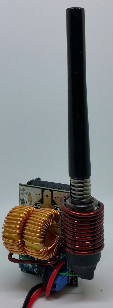
For the tactile switch, I have the method down and seems to work well. I had some pics but deleted them by mistake.
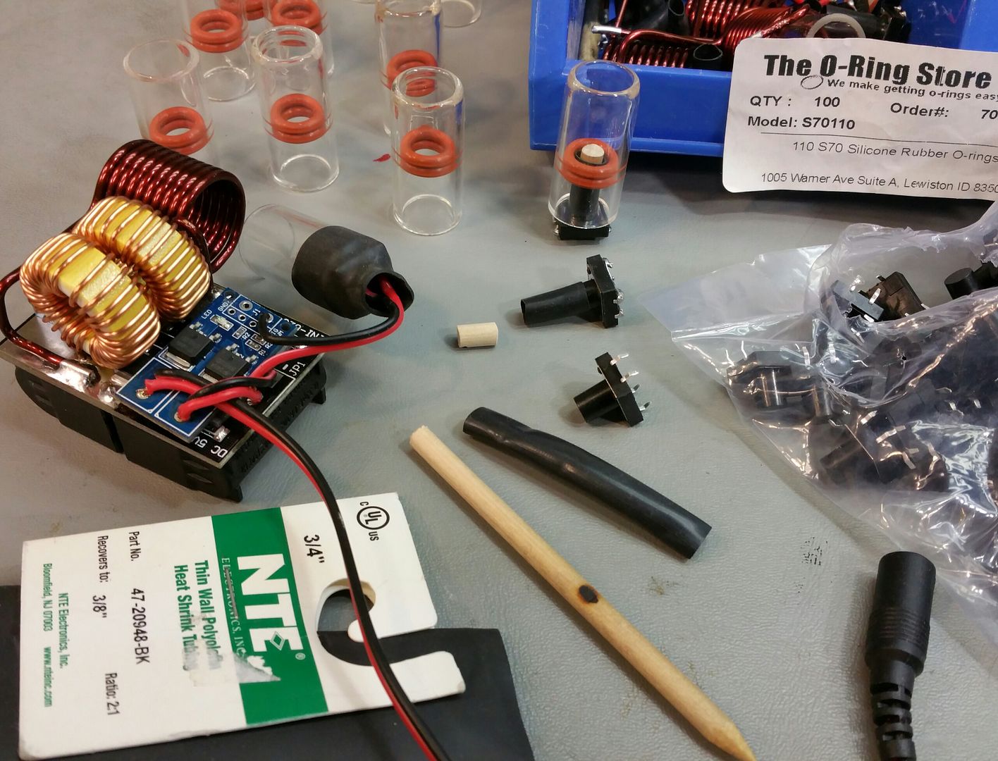
Instead of the black cap over the switch, I decided to go with 3/4" shrink tubing. It holds the switch in place better and holds it tightly against the bottom of the glass tube. Also, acts as a strain relief for the wires. Did I say it's cheaper too....
The glass tube is just long enough (35mm) for the properly adjusted VC and button mechanism.
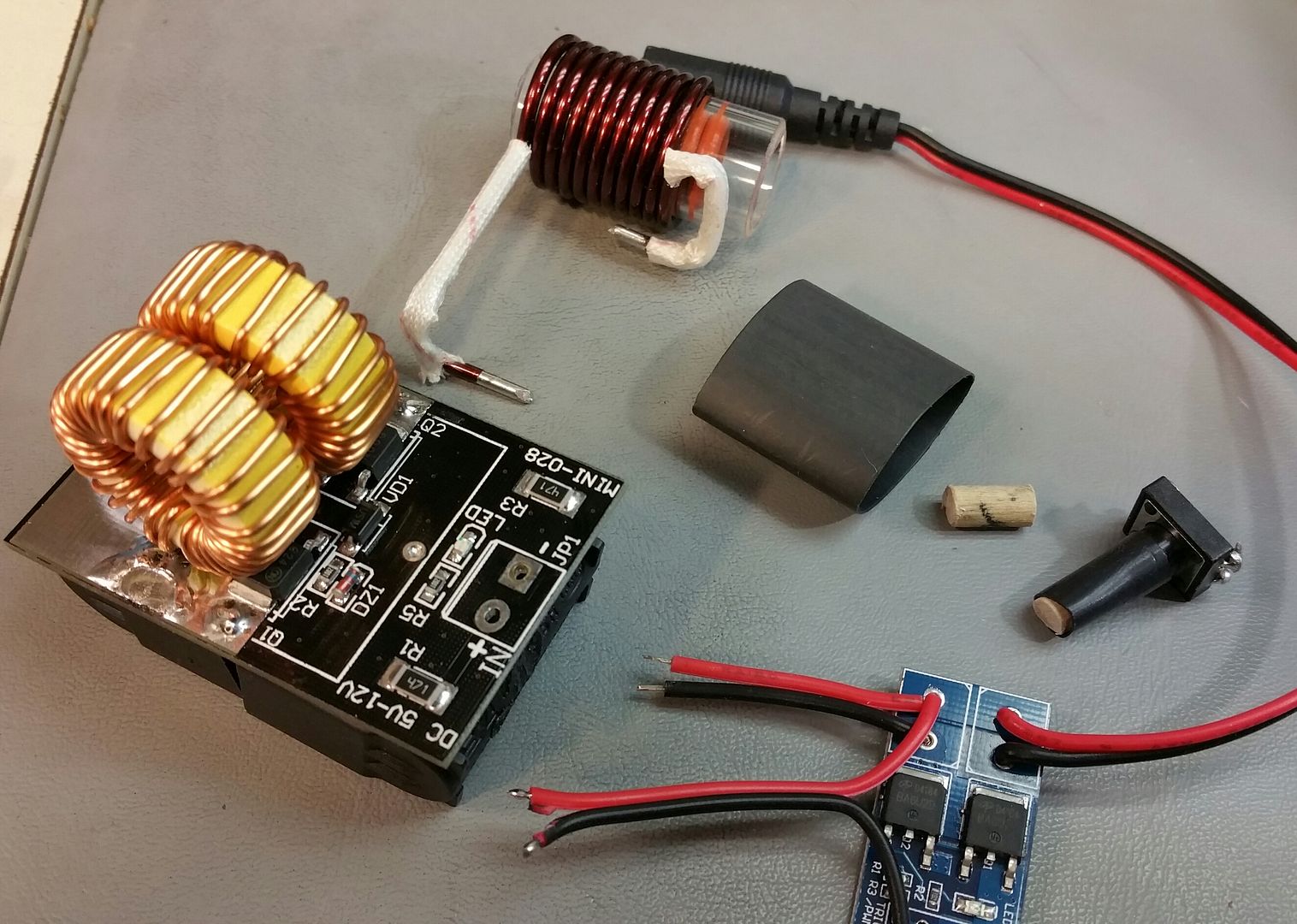
I have now configured the FET switch to be like a daughter board on the coil driver board by using thick double sided rubber tape. Also removed those chintzy connectors. Hate those ones, so un-reliable. Mounted the coil more to the Jars orientation and testing.... testing... testing...
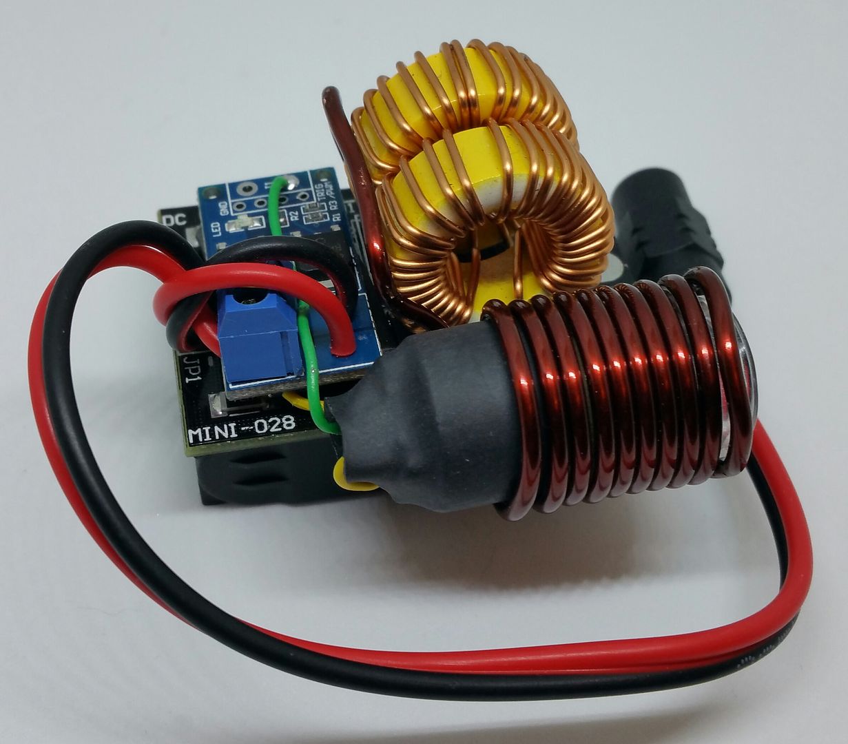
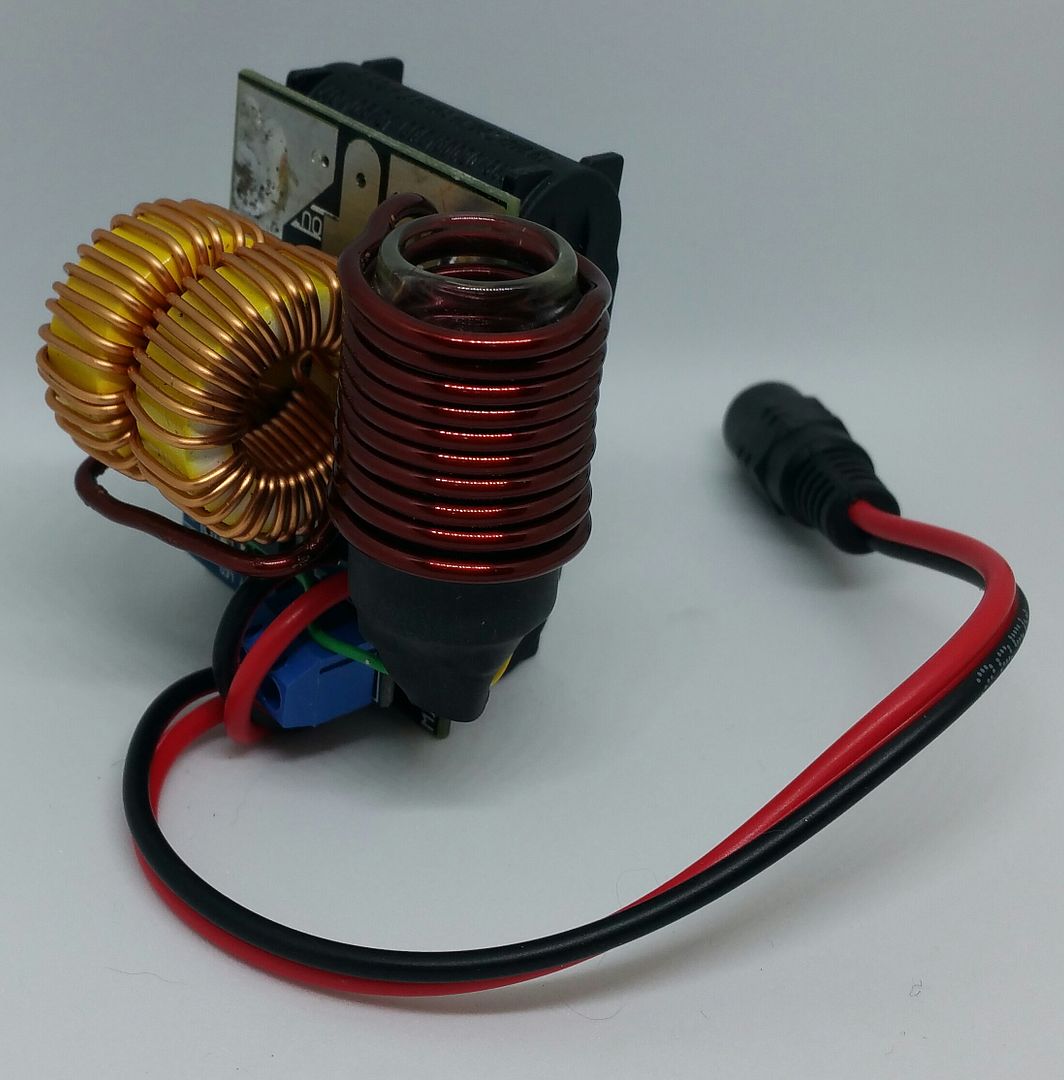
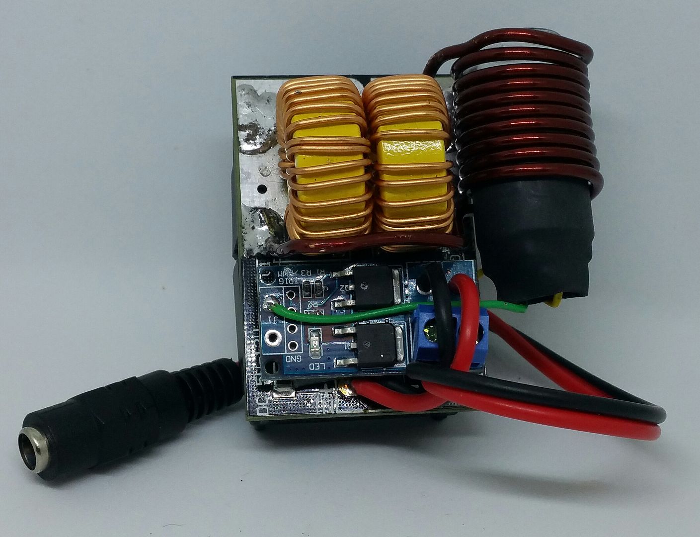
Pipes out,
So guy's, where to start. First off, my apologies, for what has turned out to be a prime example of chasing a wild goose. I'd like to back up to before I had the testing in the car fiasco. That happened at the same time I was getting reports of some power supply hiccups as we were pushing the threshold of ratings. This is where I went off trick with experimenting with double looping and thinner AWG wire in an attempt to cut down on current output.
Let's forget all the 16 AWG stuff altogether as the best solution right in front of our noses. Multiple looping was working because of, what I believe, was detuning the tuned circuit and or the mentioned self heating.
Moving forward.
100% back on track and no messing with anything but the stock coil. I figure the coil is already tuned for maximized power and therefore left alone. The key is in the depth the coil is allowed to be put into it. Previously, I was inserting too far and pushed the power supply into CC mode and I never really realized it's effect. Push th VC even deeper and the supply would start to hiccup. Now with the amp meter hooked up I can find the depth that calls for 5.5 amps and shelf it off so it's impossible to go past that point. The reason all became cloudy the first time was the supplies behavior when pushed beyond it's rating. OK, enough, explaining my fuckup. Hopefully, my posts might have at least being entertaining.

Here's the good news, when the height is adjusted correctly at 5.5 amps, you get a 5 SECOND CLICK!!!
 Yes, a 5 second click!!!
Adjusting the depth to be 1-2 mm below the cap top is the 5.5 amp mark. Beyond that, normal power supplies would give bad misleading behavior as well as make hefty supplies, like a car battery, very quick.
OK, I'm almost over that...


For the tactile switch, I have the method down and seems to work well. I had some pics but deleted them by mistake.

Instead of the black cap over the switch, I decided to go with 3/4" shrink tubing. It holds the switch in place better and holds it tightly against the bottom of the glass tube. Also, acts as a strain relief for the wires. Did I say it's cheaper too....

The glass tube is just long enough (35mm) for the properly adjusted VC and button mechanism.
I have now configured the FET switch to be like a daughter board on the coil driver board by using thick double sided rubber tape. Also removed those chintzy connectors. Hate those ones, so un-reliable. Mounted the coil more to the Jars orientation and testing.... testing... testing...


Pipes out,

GreenHopper
20 going on 60
Ha you could have told me pixie dust got in the works and was jamming everything up and messing up your tests and I would have believed ya.
Looks very neat bud, I'm gonna say:

Looks very neat bud, I'm gonna say:

natural farmer
Well-Known Member
Can't get enough of your genius...Now that's the kind of "out of the box" thinking that can get one's ideas flowing. But I don't think it's functional in our case as the heat is only making oils very warm to speed up evaporation. Fun thought though.
So guy's, where to start. First off, my apologies, for what has turned out to be a prime example of chasing a wild goose. I'd like to back up to before I had the testing in the car fiasco. That happened at the same time I was getting reports of some power supply hiccups as we were pushing the threshold of ratings. This is where I went off trick with experimenting with double looping and thinner AWG wire in an attempt to cut down on current output.
Let's forget all the 16 AWG stuff altogether as the best solution right in front of our noses. Multiple looping was working because of, what I believe, was detuning the tuned circuit and or the mentioned self heating.
Moving forward.
100% back on track and no messing with anything but the stock coil. I figure the coil is already tuned for maximized power and therefore left alone. The key is in the depth the coil is allowed to be put into it. Previously, I was inserting too far and pushed the power supply into CC mode and I never really realized it's effect. Push th VC even deeper and the supply would start to hiccup. Now with the amp meter hooked up I can find the depth that calls for 5.5 amps and shelf it off so it's impossible to go past that point. The reason all became cloudy the first time was the supplies behavior when pushed beyond it's rating. OK, enough, explaining my fuckup. Hopefully, my posts might have at least being entertaining.
Here's the good news, when the height is adjusted correctly at 5.5 amps, you get a 5 SECOND CLICK!!!Yes, a 5 second click!!!
Adjusting the depth to be 1-2 mm below the cap top is the 5.5 amp mark. Beyond that, normal power supplies would give bad misleading behavior as well as make hefty supplies, like a car battery, very quick.
OK, I'm almost over that...

For the tactile switch, I have the method down and seems to work well. I had some pics but deleted them by mistake.
Instead of the black cap over the switch, I decided to go with 3/4" shrink tubing. It holds the switch in place better and holds it tightly against the bottom of the glass tube. Also, acts as a strain relief for the wires. Did I say it's cheaper too....
The glass tube is just long enough (35mm) for the properly adjusted VC and button mechanism.
I have now configured the FET switch to be like a daughter board on the coil driver board by using thick double sided rubber tape. Also removed those chintzy connectors. Hate those ones, so un-reliable. Mounted the coil more to the Jars orientation and testing.... testing... testing...


Pipes out,

ander
Well-Known Member
Thanks Pipes. Sweet induction dreams...Pipes out,
I have begun assembly. Did a lot of the tedious prep work last night. Preparing wire harnesses and removed all those stupid blue connectors. What a PITA. Now that the Jarhead is doable, I'll concentrate making those up until the other parts get in for the stand-alone portable unit. At the mercy of the shipping companies for that time line. I have an addition 15 of everything else which should be here first anyway.
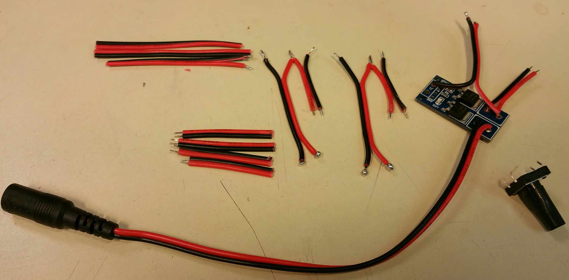
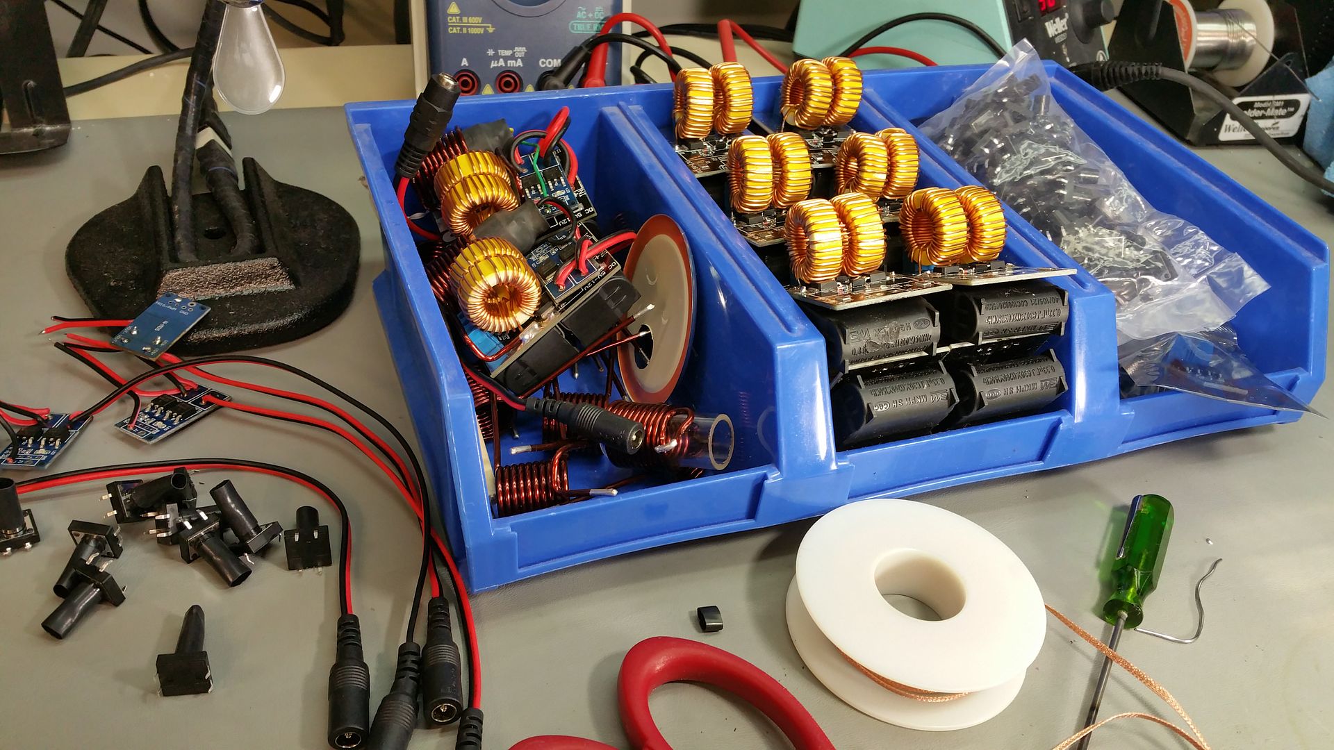
I received the actual tactile switch I ordered for this pup which is a little different. It has a protruding button which I put a piece of shrink wrap over and a small dowel will be used to extend it to the bottom of the VC. The length of this dowel is also the height adjustment. The switch is still held to the bottom of the glass tube by shrink wrap as well.
I have to go pick up some more Masonry jars but this part of the assembly process shouldn't take long. So I will be reaching out to the fellow FCers on my list to see if they want the "Jarhead VC Induction Heater" or want to wait for the stand-alone portable unit. Still thinking of what to call it. What do you guys think about Jarhead for the home/car unit?
Pipes almost out...

Last edited:
Here's some more production porn for the clan.
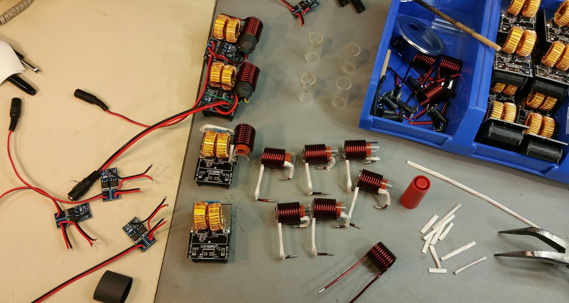
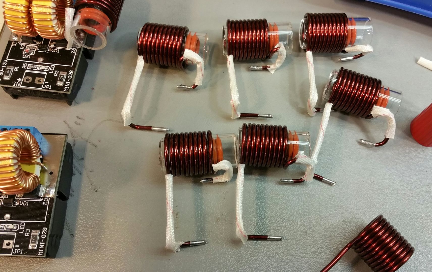
Another busy and fruitful night. Started with cutting some glass and heat treating the edges.
I think I'll just post the pics as should pretty much sum it up.
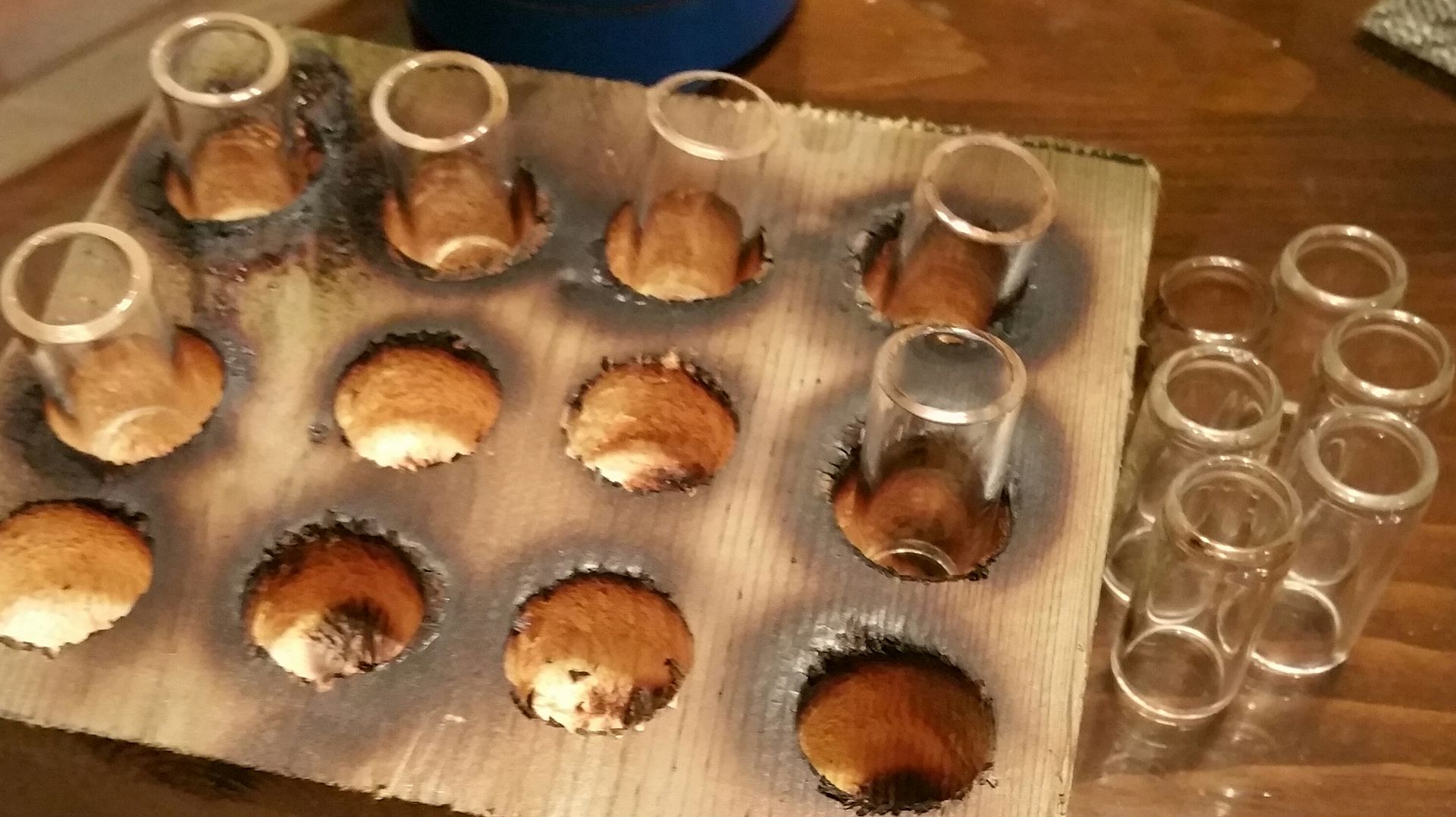
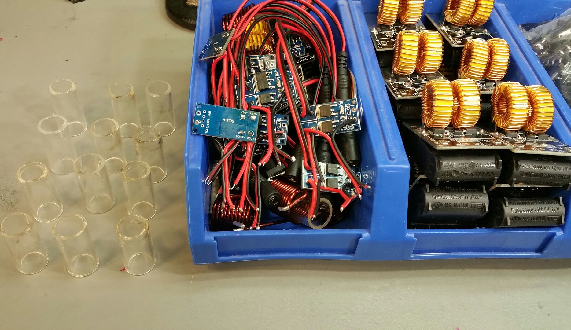
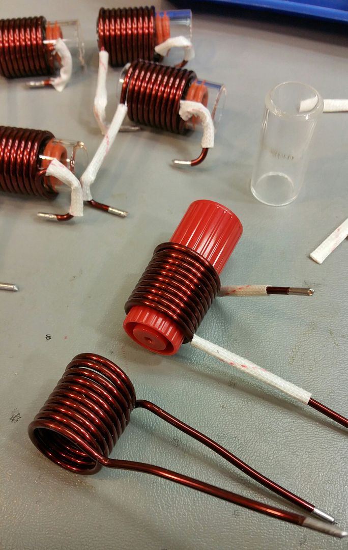

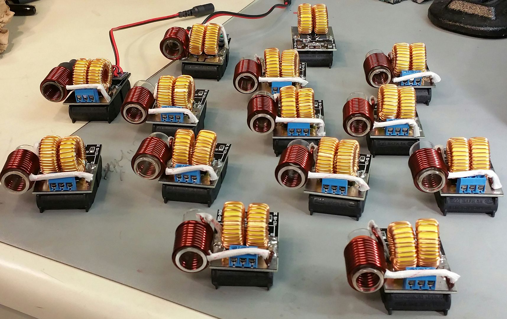
At this point, I took a break.


Then, when I got done playing tanks, I got back to it. Incoming!!!
Get in formation, ... we got work to do!
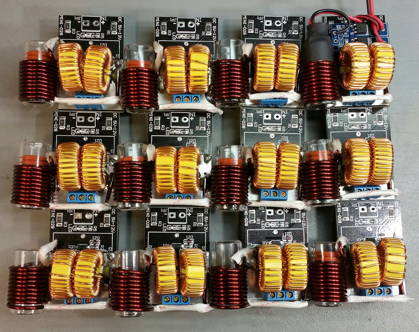
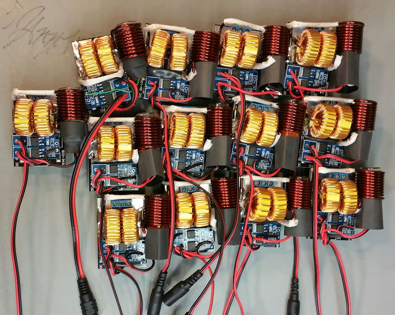
Then my time and energy were running low. Just need to calibrate the switch distances and heat shrink them it. The main modular will then be complete and functional. All that is left is the Jars, drilled and fitted, as well as the LED indicator and PCB to bring it all together.
Pipes definitely out...
Edit, too funny. was just looking the the last picture and I see a wiring mistake. Can anyone else see it? Not the top left as it was the first and just configured a little different.
Wouldn't have passed the QC check...
Another busy and fruitful night. Started with cutting some glass and heat treating the edges.
I think I'll just post the pics as should pretty much sum it up.


At this point, I took a break.


Then, when I got done playing tanks, I got back to it. Incoming!!!
Get in formation,
 ... we got work to do!

Then my time and energy were running low. Just need to calibrate the switch distances and heat shrink them it. The main modular will then be complete and functional. All that is left is the Jars, drilled and fitted, as well as the LED indicator and PCB to bring it all together.
Pipes definitely out...

Edit, too funny. was just looking the the last picture and I see a wiring mistake. Can anyone else see it? Not the top left as it was the first and just configured a little different.
Wouldn't have passed the QC check...

Last edited:
The Beagle
That wasn't a microdose
That's awesome, really looking forward to get on the list for your second batch. (Because there's gonna be a second batch right?)
GreenHopper
20 going on 60
Yes, more batches to come! Next batch will be the portable stand alone unit.
I went all around to different dollar stores to find the Mason jars but they all have every size but that one. However, they all had a different type of jar so ended up going with them instead. Actually, it's a better jar as glass is thicker and metal lid is also thicker and polished.
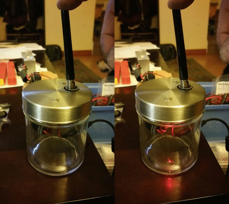
There is a magnet in the center for holding the VC to cool down. I'm on the fence still on whether an additional LED is really needed. The internal LED is fairly bright and can be seen from most angles.
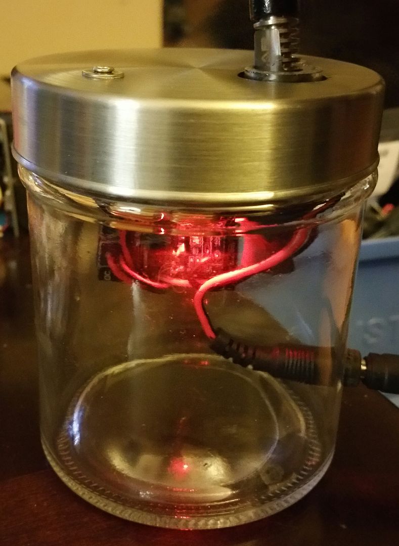
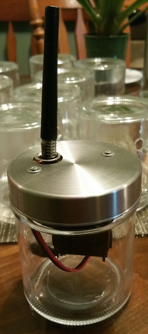
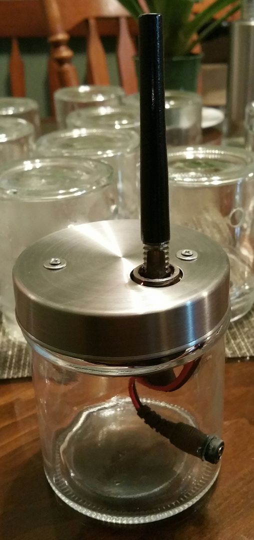
Moving right along.
I went all around to different dollar stores to find the Mason jars but they all have every size but that one. However, they all had a different type of jar so ended up going with them instead. Actually, it's a better jar as glass is thicker and metal lid is also thicker and polished.

There is a magnet in the center for holding the VC to cool down. I'm on the fence still on whether an additional LED is really needed. The internal LED is fairly bright and can be seen from most angles.


Moving right along.

natural farmer
Well-Known Member
These jars look really nice compared to the classic mason jars! 
Since you compacted everything there is even room for a few buds at the bottom!
 Does the plug come out easily if you push it from outside or is it more of a permanent fit?

Since you compacted everything there is even room for a few buds at the bottom!

 Does the plug come out easily if you push it from outside or is it more of a permanent fit?
I think so too.
It's pressure fit it. I used needle nose plyers to install. Can be pushed back out without a lot of effort but need plyers or long fingers to get it back in.
What's kind of cool is it can be dressed up very easily with an insert that would expand inside the jar. It actually came with one with the product name etc. Going to have to think of one to kick it off.

Hogni
Honi soit qui mal y pense
Sorry, have to come back to my unanswered question about the wooden case. Possible or to dangerous?
Perhaps a body out of a soft stone like serpentine or soap stone?
The new jar looks much better than the old ones but not being really happy with imagination to put permanently a jar onto my table. Its not really decorative in my eyes.
BTW @Pipes , what's your actual price for the heater?
Perhaps a body out of a soft stone like serpentine or soap stone?
The new jar looks much better than the old ones but not being really happy with imagination to put permanently a jar onto my table. Its not really decorative in my eyes.
BTW @Pipes , what's your actual price for the heater?
Last edited:
natural farmer
Well-Known Member
Sorry, have to come back to my unanswered question about the wooden case. Possible or to dangerous?
Perhaps a body out of a soft stone like serpentine or soap stone?
The new jar looks much better than the old ones but not being really happy with imagination to put permanently a jar onto my table. Its not really decorative in my eyes.
BTW @Pipes , what's your actual price for the heater?
What about if you paint it with some beautiful colours? Maybe a friend can draw something artsy? Or kids paint it? So many possibilities...

I decided on a container that is easy to obtain, safe, and economical. A wooden box is a doable idea but wouldn't pass any electrical regulations or code such as UL or CSA. Not that I'm concerned about code, as they do have some ridiculous criteria, but I am about safety. We are dealing with a device that produces heat, and is high current driven, so I'm not comfortable making a wood enclosure to sell.Sorry, have to come back to my unanswered question about the wooden case. Possible or to dangerous?
Perhaps a body out of a soft stone like serpentine or soap stone?
The new jar looks much better than the old ones but not being really happy with imagination to put permanently a jar onto my table. Its not really decorative in my eyes.
BTW @Pipes , what's your actual price for the heater?
However, one can always mount the compacted modular into any container they like. Even leave it mounted to the lid and mount like that anywhere.
In this regard, the Mason jar was better.
Also, like NF said, lots of possibilities for dressing it up, wrap around art on the inside or spray paint the inside. A nice silver spray paint on the inside of jar would give a cool effect I bet.
Price is something I keep thinking about.
The Jarhead unit, $65 plus shipping.
The upcoming Standalone, will be $95 plus shipping.

I just realized I missed a picture of the underside of the lid. Perhaps an important one for many. The lid screws down in like 1/3 turn so no worries about over twisting the power line. The threads are of a nylon plastic material so a nice smooth feel while screwing or unscrewing.
The modular is mounted on a small PCB which, in turn, provides the means to be mounted to the lid. There are small 3mm spacers between the PCB and the lid. There is also a magnet attached to the lid in the space between the PCB and lid.
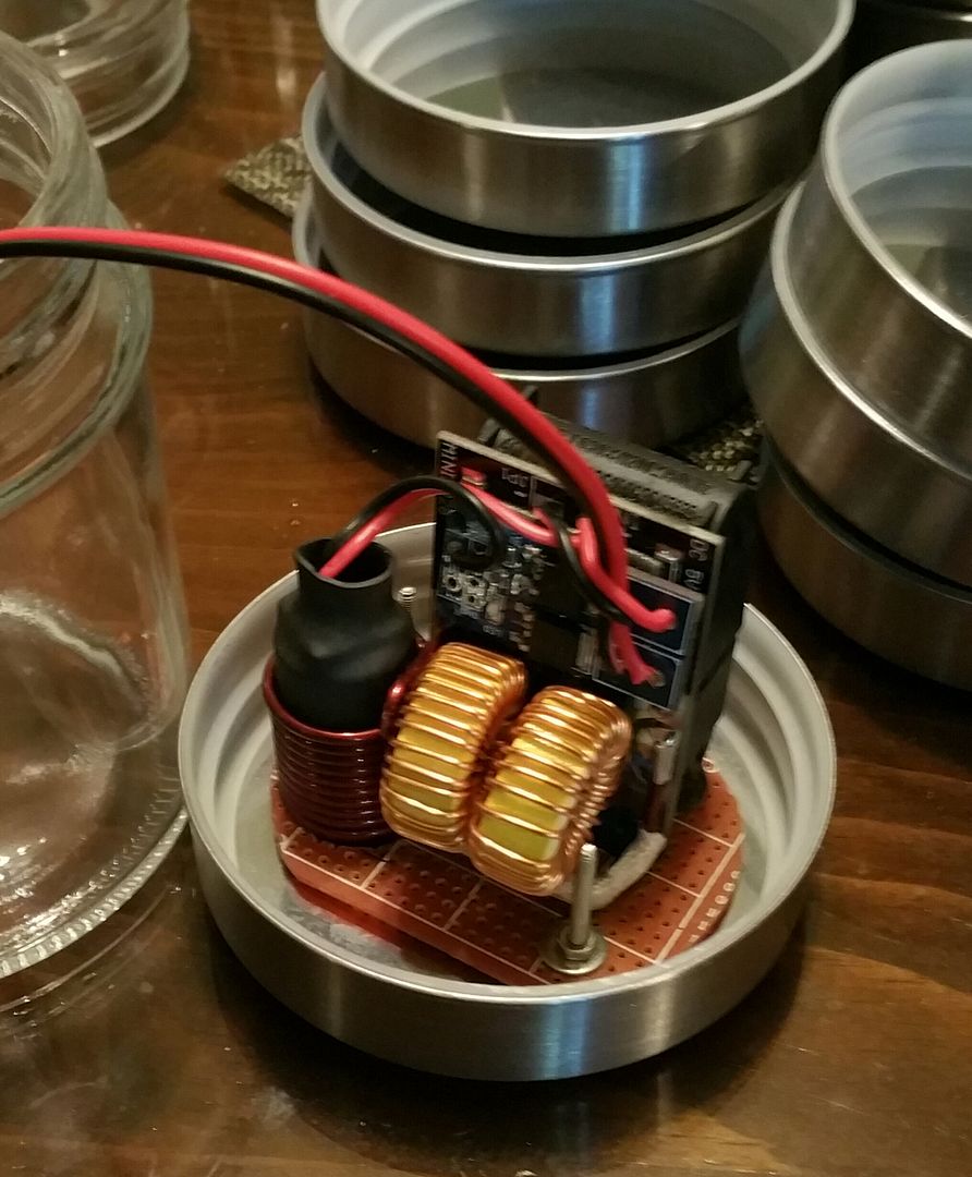
The modular is mounted on a small PCB which, in turn, provides the means to be mounted to the lid. There are small 3mm spacers between the PCB and the lid. There is also a magnet attached to the lid in the space between the PCB and lid.

natural farmer
Well-Known Member
So tidy...I just realized I missed a picture of the underside of the lid. Perhaps an important one for many. The lid screws down in like 1/3 turn so no worries about over twisting the power line. The threads are of a nylon plastic material so a nice smooth feel while screwing or unscrewing.
The modular is mounted on a small PCB which, in turn, provides the means to be mounted to the lid. There are small 3mm spacers between the PCB and the lid. There is also a magnet attached to the lid in the space between the PCB and lid.


Hogni
Honi soit qui mal y pense
Wouldn't a case made of this serpentine look lovely?
GeeWhiz
Well-Known Member
OMG.. you are an amazing craftsman. I really need to know how you make those bodies though? and what condenser do you use when making your own body?Yes, more batches to come! Next batch will be the portable stand alone unit.
I went all around to different dollar stores to find the Mason jars but they all have every size but that one. However, they all had a different type of jar so ended up going with them instead. Actually, it's a better jar as glass is thicker and metal lid is also thicker and polished.

There is a magnet in the center for holding the VC to cool down. I'm on the fence still on whether an additional LED is really needed. The internal LED is fairly bright and can be seen from most angles.


Moving right along.
