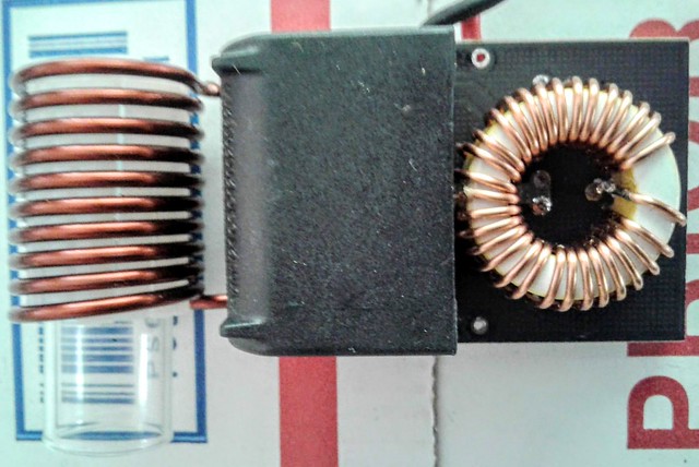
Coil work has commenced. This must be the tricky part. I've used stock coils since I started this project. They are heavy 12 gauge coils ready for some serious duty. They barely get warm enough to worry about on an open frame device. They are quick to heat the VC and they are dirt simple. The hardest part of this project is settling on an orientation for the coil and a means to hold the elevation of the VC.
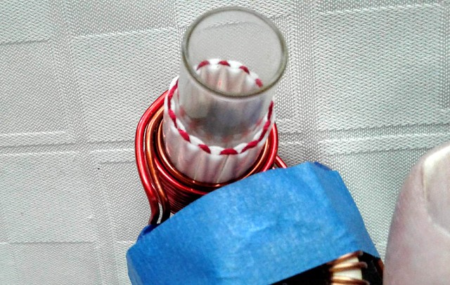
I wound a 9 turn 14 gauge coil some time ago. It has no insulation so I made sure the coils were well separated. I put a glass vial inside the coil to keep the VC from shorting the coil out. I centered the tip in the coil.
First of all, damn these smaller gauge coils get hot! There are a couple of things at play here. The coils are basically a short circuit to the circuit itself. There is N amount of resistance and the power imparted is basically the current running through the coil minus inefficiencies. Changing coils changes these characteristics.
There is no way I can run this 14 gauge coil in an open frame. Simply too hot. Could make a bud roaster out of it though.
Now I'll mishmash a few thin gs together to compare. I was getting about 13 seconds on the baseline model with an aggressive heating. Centering the cap in the coil. The coil is way over-sized and this adds to the impedance. I was getting readings in the 0.05 or less ohms on MODs. This is pretty much a buss bar across the output. And because it only gets warm, it is a fairly stable load as well. This setup pulled about 60 watts.
First round with the 14 gauge coil was interesting. 16 seconds to the click - 8 amps of current draw as opposed to the previous 6. Something is pulling down my input voltage in the setup but I was registering 72 watts. More energy and a slower click. Remember the circuit is very different also being cut in half.
Also consider the extra heat imparted to the coil. Copper changes resistance with heat. Therefore the circuit "weaken" as the coil warms up. It is always good to have a stable heater. I will see if a pair of 15 gauge wires will equal the 12 gauge performance. The circular mils should be equivalent. I think I will also opt for a longer coil. Looking to 'untarget' the heat a little. A larger diameter is definitely called for.
The VC got hot in the 16 seconds. Very Hot! As did the coil. So I adjusted the cup to be nearly level with the bottom of the coil instead of through. That went okay. 10 seconds to the click and a nice well cooked load. So this is the second thing I am not to sure about going this route. It is much more finicky.
Putting this in a safe housing will alleviate some of the heat concerns but it does require thermal fusing if that is the route. And the power level I'm seeing now is alarming. I need to see if this is something about my connections.
Take away so far, tuned coils are a liability. I don't really have the tools to take on this level of development to anything meaningful. This very quick little overview experiment was more about the right questions to ask than present any real data. Heat, stability, target heat zones... now those have all come into focus from this quick study.
----------------------------------------
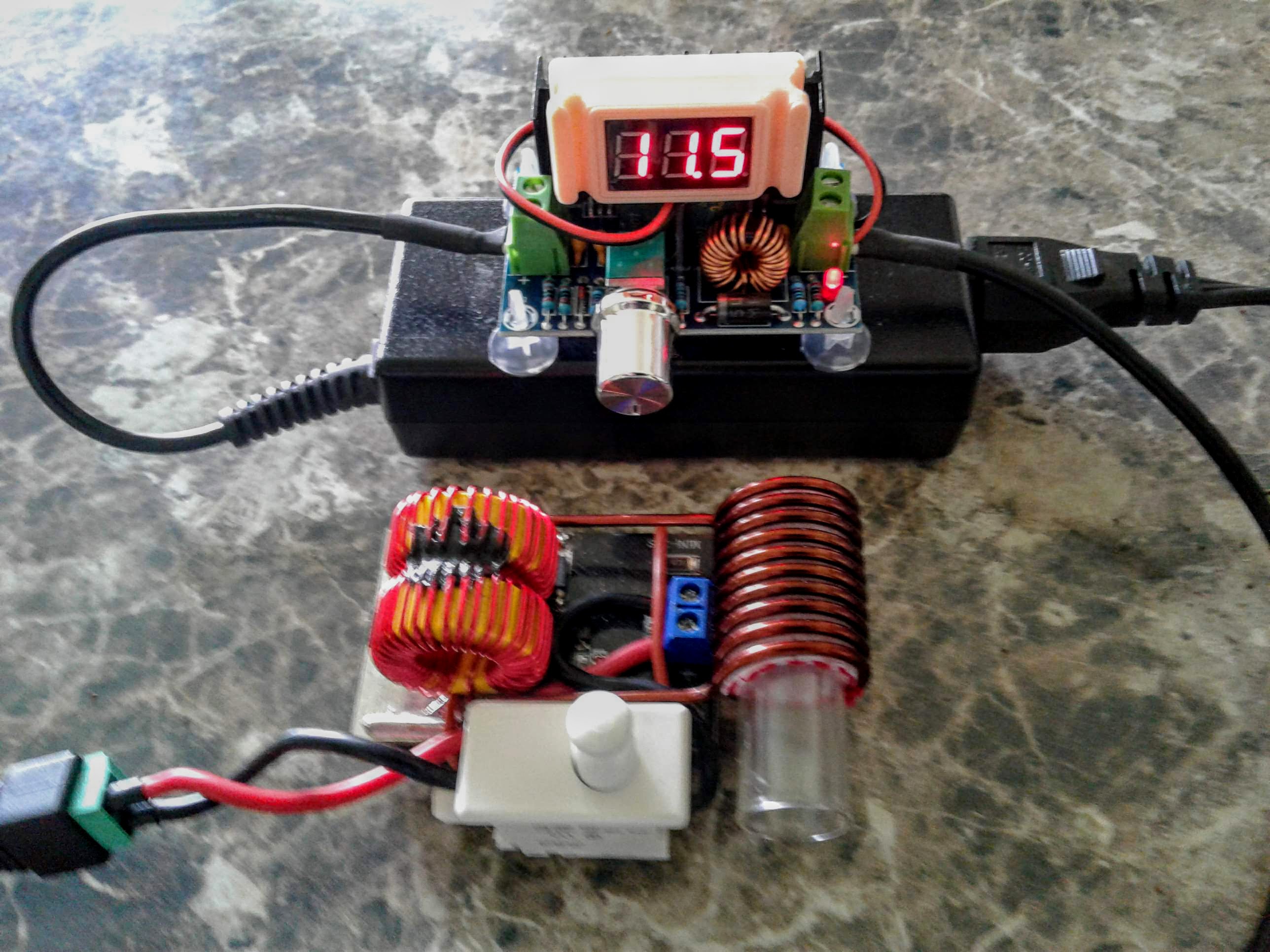
And to continue. I rebuilt the Half Pint back to the original coil. I also arranged the remaining components a little logically and robustly. Please remember that this is just a proof of circuit module. I am short on salvage switches so the little green dot is just soldered in activating the circuit.
Notice the center-tap that is wired back to the board. It doubles as support and a positive binding post on the opposite side. The hole is only good for 18 gauge.
I cut the trace as I talked about earlier. Now I see I could have bridged the switch across the single hole (+) and the double holes that the small red with is going to. I may still do something like that. Basically cut the trace and install a tactile switch directly to the board.
Also notice the location for the negative power trace. I don't know about you, but these traces appear to be resistors. These are meant to carry 10 freaking amps. I'm going to have to look up some design rules. However, I opted not to use the thin traces for both plus and minus. Plus goes directly to the inductor center-tap and the negative is directly connected to the trace that joins the two MOSFETs. There is no other place to make this a good solid connection without trace losses. Just so you know. Even the via's are seriously lacking. They work, but why not improve things. So I have my ideas for the next go around but this is a nice little, and I mean seriously trimmed down, induction heating wand, albeit corded.

Performance - FUCK THIS! <slams door and stomps off> respect to the makers. Seriously. I am not an EE. I tinker around and know more than enough to be dangerous. But this circuit doesn't behave according to the rules of logic. The new layout is far more efficient than yesterday. There is no change other than physical location of the components and their orientation. This layout is very tame, yet you put 12.6V on it and it will roast your bud. I'm having trouble getting 60 watts out of it, which is a lot, don't get me wrong. The 7.2V output is only 21 watts and 4watts of that is housekeeping. Therefore this test also shows that the usable voltage range has been narrowed or at least shifted. This unit will require a 3s cell arrangement if not a 12.6V brick straight up. I'll have to follow up with some power numbers.
Overall this thing performs. It provides a smaller package by droves and the removal of the MOSFET switch just simplifies life even more.


 At least I can get moving again. That hiatus was too long between shipments.
 The base station, The Coupler, can have the plug-in for the HalfPint w/ 8v output. That means, of course, the Dee...Lux model is a dual IH.


 Finally did something with the 15 and 14 gauge magnet wire. Would be shame for it to go to waste. So I came up with a plan -


 ! Now i finally got idea on what to do with those knockoff legos they gift me at the super


