DIY Induction Heater Builds and References

TommyDee

Vaporitor
I'd like to start this thread off with inviting all the DIY IH efforts.

I invite developments as well as builds to participate here to share knowledge and understanding.

Myself, I am in 4 for 4 on home-built Mini ZVS 120W modules. Now that I have some magnet wire, efforts are under way to qualify coils.

My aim is to make a small handheld portable that utilizes a cradle to maintain charge.

...this below ain't it :cool:

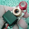
But this is the entry I would like for this first page. This is the Mini ZVS 120 watt induction heater.
Improvements to this module include;
a) The positive power circuit and the control circuit have been separated by cutting the positive trace under the 330nf capacitors.
b) A simple momentary switch, or several in parallel, can be placed anywhere. This is a scavenged switch that is ShoeGoo'd into place. This is wired between the positive input lead and the positive output lead. If you maintain the blue connectors, the positive input lead is now a switch input for the gate circuit; the center pin of the output connector (3-pin) is positive power in put.
c) A 9-turn coil of the original ID and wound closer together raises the resting current about 25%. I need to see what 11-turn coils will change. This one is a little too hot at a 12.6 volt input. I also need to see what axial orientation does to resting current. Oddly enough, orientation is in play, unfortunately.
d) The traces on these boards are woefully undersized. There is one via each on my board to power the source lead of the FET. Therefore I scraped clean the trace between the two S-leads and soldered the 16 gauge negative lead directly to that trace. The via's will power the gate circuit as normal. Same with the positive lead. I wired the 16 gauge positive lead directly to the coil lead.

Result; 5-6 second very hot heat-up on a 19mm coil. It runs about 75 watts at 10.5 volts. I want to raise that 10.5v to 12.6v at this wattage. I'm going to try to do this with the coil alone.

On a cord and a little box, this is a cute little heater.

20200520_131003.jpg

Reference: IH Bits&Pieces thread
 

TommyDee

Vaporitor
Interesting results on the first test cycle. They came in a paired box and a single. The pair performed well on the initial internal resistance test at 110 m-ohms and what I assume was the single read 70 m-ohm. After the capacity test cycle, one of the pair dropped to 90 m-ohms. These numbers are moot as this is highly suspect but it gives me a ballpark range. The capacity came out likewise similar for the pair at 1100mah (rated minimum) and the single read 1070mah.

I ran the first test at a modest 1 amp charge/discharge rate. I am running the test again at 0.5 amp charge/discharge rate.

The older cells have performed under their conditions and within their IMR specification. They don't get warm while using them and therefore they are well suited. The 700mah is a limiting factor until I get efficiency up. Slower heaters are definitely less efficient.

This represents a ~30% improvement on the performance of smaller li-ion cells. I look forward to seeing how well matched they remain throughout a day's usage. My older eFest 14500 (red) don't fare too well in a shared pack. The purple ones are holding up.

I need to design up a battery carrier.

The coil fixture for the 2-up coil is printed. 12 turn in total; 5T over 7T.
 

TommyDee

Vaporitor
And the Tests are done on the 18350 cells. They all reported under 1100mah but well over 1000mah. Can't wait to put them to the test. I do believe the capacity will back-fill what was lacking from the 14500 for a full day's use. Let's hope more 18350 offering are forthcoming. Need to design the cell carrier still. Never a dull moment.

And coil test have commenced! Interesting finding - 9 turn coil was a bit heavy on the free-wheeling current at 1.75 amps where the 11 turn coil went below benchmark at around 1.3 amps. That tells me that the coil impedance is a simple factor to exploit for battery pack range. Only one tiny problem... the coil gets to long along the axis. You might have a great magnetic field but you just want the cap and tip warmed up. That is why I was hoping the 9T coil would be workable. This really doesn't help. Smaller wire? Sure. If you protect the user and know you need to do that, fine. Greater impedance means less free-wheeling current, and means a couple of other things too not important here. Let it suffice to say that meeting the original coil's intent means 12 awg wire and about 28" of length total. Using that measure assures a cool heater coil.

20200522_152702.jpg

Why the coil length bothers me. I've been running the stock coils wide open on several of the heaters. Meaning that the coil has gaps between coils and the overall unit is rather long. This is in fact how an IH for metal treatment operates. They just pump raw power into those coils. But the intent is to keep the coil cool so it remains stable. Power into an IH coil equates to the frequency the circuit runs at. And the frequency the circuit runs at in turn has a penetration depth factor to boot. Therefore, the design also has to factor in what frequency the circuit will run at. This concerns me as I am changing the component complement and this will affect frequency.

So, where does that leave me? Well, it still leaves me with 28" of 12 gauge magnet wire to wrap around the likes of a VapCap. ...not much bigger than the cap.

Okay :science:

I had thought this out for nearly a week now. I had the hunch where this was going but I wasn't sure I could master it. 3D printer and a spindle to the rescue.

Whadajathink?

20200522_152756.jpg

This is, in fact, at best guess, either a 11-1/2 or 12-1/2 turn coil. I'm probably slightly short on the length but it is a -very- compact coil. In this case, the ID is reduced with the very fortunate attribute that my little vials fit snug without any spacers. The OD is just slightly bigger than original. The overall thickness is just about the thickness of the capacitors. How fucking convenient! :rockon:

I rebuilt my original IH. Pulled all the bits and checked it over. Was hoping to replace the LED but no luck. Turns out when I blew the LED, I also blew the plated through hole on the positive input. That was interesting to chase. I did find one disturbing factor though. I should stop assuming all these boards are wired the same. Sure enough, on this board, the positive in and positive out are -not- connected together. Very convenient except that the 2 inductors (coils) are connect to the input side. Fortunately again, I was making the second prototype HalfPint IH. This works out perfect as I don't need to cut trace to separate the control circuit from the power circuit.

I also decided to put the large cap (single for HalfPint) on the side with the FETs. This leaves a beautifully clean backside with only a few circuit traces to worry about shorting with a ring. I scaped the inductor's dead-center lead for positive contact; built the sub-assembly inductor/cap combo, Scraped the negative trace between the FETs and bonded the 16 gauge black wire to it; made a positive lead and soldered it to the output connector's center pad; wires run under the cap where they are naturally strain relieved; and I solder the cap onto the board (moved 'forward') pressing down to squish the silicone wire jacket; and finally solder the 14 gauge post I soldered the positive wire to onto the center trace of the inductor. Now it's ready for the coil. And all this has to go perfectly!

20200522_165801.jpg

The switch is another salvage. I've been eyeing this installation for a while. Since the trace wasn't connected, I bridged it with the switch. How fucking convenient yet again. But this is where I got a serious let-down. I connect the circuit and fucking crickets! DUDE! SUCK! ... oh!

Remember that blown plating in the positive input hole? Yea, took me a while too. Soldered a wire top and bottom through the hole and all was good. Double-fucking-damn!

Anyways, I guess I wasn't high enough to just toss it in the brink. I noticed one of the Zener diodes looked a bit wonky. I have no idea if it is functioning. This was my goto ailment. Then I remembered the Zener is only a shunt and could be removed. That is how this little HalfPint survived the waste bin.

I must say though, this little beast is down to 3/4" thick minus the vial and it remains cool. Take that you evil jewel thieves! Performance is already a winner. The new coil is more efficient than all the rest free-wheeling at 1.2 amps at 12.3 volts. Therefore the coil and its orientation are among the best to date in my collection. Fortunate too as I like this coil in this orientation. It is simple to mount.

Power usage relative to the pack is nice. It floats around 60-75 watts in the 11-12v range. I suspect this one will be very comfortable with a 96 watt power brick (12v 8a). This circuit should also behave very well with li-ion cells.

Okay good peeps - this is the next phase for HalfPint. Onto extensive testing.

20200522_165825.jpg
 
Last edited:

Zoned89

Active Member
I just saw this and now I gotta go through here
And see if there’s any new info you’re all over this site my guy haha
 
Vapeyvaporson,
  • Like
Reactions: TommyDee

TommyDee

Vaporitor
:lmao: Never a dull moment in my shop. :rockon:

This also extends from the other site. We're at a zero'ing in phase. I'm working on 'small' and mellow portable.

If you want new tech, check out variable input voltage to dial in your 'oven'. Enjoying near on-demand IH draws. No butane so no reason not to draw while cooking. If you can tame the IH, you can probably keep up with the IH. or at least get you in a modulation range.
 

PKOK

Well-Known Member
Yippee
So we do all our business here now right?
TD you've been a busy man the past few weeks. I got a lot of catching up to do.
TD witch one is your favorite?
 
PKOK,
  • Like
Reactions: TommyDee

TommyDee

Vaporitor
Welcome to the new digs @PKOK . I am so liking -smallness-. Corded is still a bit of a 'restraint'. If the pack is sitting there next to me [3s 18650] then sessions all night. HalfPint portable has been lonely for a couple of days only in that swapping cells is still required. Having a plug-in charge solution or the cradle is needed.

The performance of this device is such that I can have a little more leeway in power. My brick is only 65 watts and it outputs 78 watts reliably. I can get down to 7 seconds on the heat cycle. My current balance of the circuit seems to limit current to about 6.5 amps at a peak charge of the cells. I think I got 5 amps at 9 volts; 45 watts. 9 volts is the battery cut-off.

As stated earlier, I believe we can manipulate the power requirements with the coil. What really excited me was to lay 2 18650's next to the HalfPint. Now that would make a nice little flat box for a heater. I think it is the right thing to do for that style product.

I'm going to try something today that will tell me how much component placement matters. More later.

...and I need to restore a baseline unit with the stock coil.
 

TommyDee

Vaporitor
Not much new for today. Circuit design got good news. Okay, placement considerations. I rotated the 180 degrees so it was proud on the switch side. I wanted to know if the coil was interfering with the inductor. Adding the offset on HalfPint ProtoII imaged above, the unit displayed the very same freewheeling current of about 0.1A for every 1.0V; 10V, 1A. That seems a good balance.

The new "Baseline ZVS" also pictured above has the original coil back on it. I'm finding these Teflon sleeves handy for transferring the cups. I use these because I lack anything else to put in there for consistent depths for analysis. And they work very well no less.

I had another thought today. Consider 2s and 3s basically as electron tanks. 3 is more than 2... 1.5 times as much actually. So what other elements seems to be tracking? Remember those coil tests above? 9 vs. 10 vs. 11T? Well, each increment was roughly a 0.1ma change per volt freewheeling (power, no VC) It is reasonable to assume this scales for the time being. SO if I up the freewheeling current to 1.5A at 10V, then I might have lowered the voltage range of the 2s packs. Let's explore...

I scale down the cells to 2/3rd. I change my power capacity to a third. Wait, weren't we just talking half? 50%! Yea, this math is funny. Just making sure you're paying attention.
Yes, we want to reduce the voltage down to 2/3 our known parameters. Turn on the coil means impedance. Impedance is based on wire length and wire gauge. I want to maintain this cool state when I up the freewheeling power levels remembering that voltage flows freer than current when it comes to generating heat. So lets look at the coil;

Coil considerations - Pairing up wire makes it 3 wire gauges larger. We need 1/2 again what we have to maintain the status quo on scaling. 12 gauge doubled is 9 gauge. Too much. I think 10 gauge and 11 gauge are going to determine total heat that the user will see. We can er on the side of 10 gauge. I can do the math but it's in the noise.

Turns consideration - When testing the 9T and 11T coils the progress was lock step with voltage at 75W. 9T maxed out my PS at just over 11V and 11T was very comfortable with the power supply. The baseline 10T coil also taxed the power supply but not the trend was obvious. More turns, higher voltage to 75 watts.

HalfPint coil paramters - The coil-back double coil you see in HalfPint is 11.5 tuns (T). I'm is a -very- comfrtable range for 3S 18650. 5.0-6.5 amps range across an actual pack range taking into account the internal resistance, the typical range is 5-6 amps and delivering 45 to 75 watts. The lag becomes notable when the cells start their decent to need ing a charge. Very convenient. Don't need meters!

2S coil considerations - If you followed me this far, you know might already be ahead of me. I'm going to reduce the coil count - reduce the coil wire length - from 11.5 to 2/3 this number... which looks like it will be 7.5 turns or 4+ on the inside and 3-ish turns on the outside. Considering it is 10 gauge, 7.5T would be taller than I think I want, but a bouble coil at so few turns will have to be stretches a little. Which is good on all fronts. I am intentionally keeping the squat in height.

So, odds? Will a 10 gauge coil at 7-1/2 turns let me have 75W performance with 2S 18650? What will the cells need to deliver with the reduced voltage? Well, fairly simple math, right around 10 amps at 7.8 volts after internal resistance puts you right at 78 watts. Huh! :D

There are many assumptions but evrything is pointing to the coil managing the usable input range. And I now you see why I am limiting 75 watts... it is a lot more current when you have less voltage.

Okay... head explode yet? Mine is finally settled with some good direction for some 2S work. This could be exiting.
 

Zoned89

Active Member
I never saw the vapcap as all that portable in the first place tbh, so I never considered making it portable lol.
The torch always game me the “I’m smoking rocks” look so I just used it at home with my diy ih, actually one I made from plans on the old fc page lol
 

TommyDee

Vaporitor
You may have hit the nail on the head @Vapeyvaporson . VapCaps are very portable and stealth if it wasn't for the torches giving you away. It is the perfect on the go combo though. However, more torch is more better it seems. There are units out there that won't pocket easily without funny looks. So I see an in.

So if the VC is portable and travels well enough for what it is, the IH offers are certainly not something you put on your person anywhere. Backpacks or totes, yea. I always carry a tote while hiking <I don't, really>. So the challenge is to make the IH as easy to carry as a torch. And it will be more stealth than a torch acoustically and visually.

Bottom line, I want to see the torch replaced with a similar device. Pocketable and portable. I now have more confident then ever that this isn't just weed talking.
 

Zoned89

Active Member
You may have hit the nail on the head @Vapeyvaporson . VapCaps are very portable and stealth if it wasn't for the torches giving you away. It is the perfect on the go combo though. However, more torch is more better it seems. There are units out there that won't pocket easily without funny looks. So I see an in.

So if the VC is portable and travels well enough for what it is, the IH offers are certainly not something you put on your person anywhere. Backpacks or totes, yea. I always carry a tote while hiking <I don't, really>. So the challenge is to make the IH as easy to carry as a torch. And it will be more stealth than a torch acoustically and visually.

Bottom line, I want to see the torch replaced with a similar device. Pocketable and portable. I now have more confident then ever that this isn't just weed talking.
If it could be smaller than a brick I’d say it would be doable, about the size of a smart phone would be a game changer. But the coils take up space, as well as everything else
 
Vapeyvaporson,
  • Like
Reactions: TommyDee

TommyDee

Vaporitor
We're close. Look at the coil on HalfPint. That is only 16mm tall installed. We're in flip-phone territory yes.

20200524_151353.jpg

3s 18650 IH in a Magic Flight tin. Think it will fool anyone?

...and the some 10 and 18 gauge wire was ordered. I opted for the red enamel because it looks cooler. I never want to see a coil or induction to hit 155'C!
The 10 gauge will likely be needed for the 2S version since it will be drawing into the 10 amp range for a full 75 watts.
 
Last edited:

TommyDee

Vaporitor
Sorry for the lack of action over the last while. Got sidetracked a bit on other things.

Today the 10 awg wire came in so a short length test is due for 7.2V operation. Really looking forward to see how this behaves. Also got my second meter.

Update on the HalfPint. Been using the devil out of it. The coil needs one more wind in length at least. Turns out the temperature adjustment is so touchy now that this is still a very hot IH. Not in speed but in the time it takes to click the clicker. Great Rips! Haven't combusted when I minded the click. Both the '18 and '19 tips have just toasted the holy snot out of the herb.
 

TommyDee

Vaporitor
Well now. I finally decided to see what's out there for sub-$100 two channel scope.
There seems to be a host of USB offerings. Any advice from you sparkies out there?
 
TommyDee,

TommyDee

Vaporitor
Lost one of my vials today. Edit- lost 2 vials today. Really bummed about that. Now I'll have to make some cups.

The extra turns project

I rebuilt HalfPint today into its brother's configuration. Also wound the new coil with extra turns.
These extra couple of turns on the new coil dialed in the power range I was looking for in relation to input voltage.

Freewheeling current draw was still under 0.1 amp per volt. I expected this value to go down a little more with the extra wire length. I will be very interested to see if this freewheeling current remains constant when I go for the 2S configuration with the 12 gauge, 7 wind coil.
The extra turn are providing lower coupling currents for a given input voltage. This is an interesting way to move the input the range into focus.
For techies - the original 11-1/2 turn coil was to meet the original length or and gauge of the 'standard ZVS coil'. The performance was very similar between the standard and the double over-coil. Here, the wire gauge is identical and the length is upped to 13-1/4 turns, providing the height of one more coil.

I hope I am doing this smart enough. I am using the '18 SS tip and cap as the 'standard' and as the 'worst case'. Somewhere I need to set safety standards and the current these things draw has a lot to do with it. We have history with 12v at 5A, 6A, 8A, and now possibly 10 amps to include voltage control. These things are very honest about their power requirements. Insert the most ferrous tip available, insert it as deep as possible within the coil, and take a voltage, and current reading.

We are gathering design parameters and requirements. One design parameter is compacts - Getting there. A second is one that should make this safe to hold without any housing. This particular build uses the inherent minimal standards for circuit self-heating. A crude way of saying standards that exist that let a designer decide what the allowable temperature rise will be. This is fair game in the safety industry to a point. However, yes, significant heat is allowed to build up during use as long as the user is not exposed to it. Therefore, this -requirement- is above and beyond and requires continued engineering attention. I won't, however. save you from yourself. If you want to hold the button down and cook the thing, you bought it and the blisters your foolish endeavor brought on. Simple only works when people respect the appliance.

Another specification I want to meet is having this be a 6-amp device. I think I am right about there. I was getting 5.5 amps at just under 12 volts.

I have a new form-factor in mind with the 18350 cells as hosts. Right now, HalfPint will stuff in a box with inside dimension of 80mm x 38mm x 19mm If I double that, I can add cells and intelligence in a area of 24mm x 38mm x 19mm.

Some new glamor shorts...

20200603_133659.jpg20200603_134040 (1).jpg20200603_133634.jpg
 

TommyDee

Vaporitor
18350 vs. 14500 is barely a competition anymore. Indeed, these 18350 package just about as well as the 14500. The 18350 pack is a little shorter overall and a little thicker than the 14500. The trade-off is nearly half again the capacity. I get a solid 600mah out of the 14500 eFest cells and I expect to get a solid 1000mah out of the eFest 18350's so the power density far outweighs the physical size. I was able to maintain the cell removal hole in both cases.

Let's review what is currently being studied;

@Stark1 - my strongest critic's perspective if you please; I offer you a prototype of a battery powered coffee table IH - 90mm x 90mm x 24mm with room to spare. Has some options for style. The concept behind this is that the entire circuit, including cells and BMS can be done on a single board with no wire.

Coil placement proud of the 24mm height could reduce the periphery to 90mm x 60mm x 24mm +plus a 'feature'.

I really see this as an 'inlay circuit' to a wooden artisan piece. The plastic case is just to show sizes of elements and represents the stated sizes on the outside dimensions.
It's essentially a couple of business cards in size.

So what do we call this? FlatPack[tm][r] for now.

20200604_161009.jpg

And the wand got an update today. @Stark1 - even this pack will power your Flix. IH doesn't have to mean bulk. It does need care however. This is still HalfPint. I'm working on a housing for it. It will get a new coil but for now, this is a nice little handheld ready for any power level I want to give it - More on this housing HalfPint later.

20200604_161150.jpg
The battery pack needs a couple of end-caps or silicon rubber. Note to self; I need to get these up on Thingiverse.

And we still have the first attempt at streamlining - The Runt. If you recall, both cap and both coils reside on once side of the board with heavy 14 gauge buss bars connecting the LC circuit. Today I put the 11-turn coil and the pair of switches on there. Firing can be operated from from the red coil mounted switch from before and the new green button soldered to the circuit board. Also added a 18 gauge plug on a short leash. Overall a robust little chunk of IH hardware looking for a small box.

This one still registers a little on the high side for free-running power consumption. This one reads higher than all the others.

Anyway, The Runt

20200604_161205.jpg

Notice the new 'hook' in the center. This was to accommodate the new switch regime. If you recall, this had a MOSFET switch attached w/ 2x 18650's.
At 11-turns, this is slightly milder than the 'standard'.

Speaking of which, the standard bearer is not this unit. Built and wired stock except the hardened power connections. This unit is one that I have slated for a small wooden box project. It sits beautifully on top of the 18350 pack and it just begs to be housed. Once I settle on a coil, this will be my -own-.

The 'Standard'

20200604_161220.jpg

And there is an Alpine 2020 on the way within the next 30 days so happy skippy do da day,

All those wires in the first image... right now the unit is hardwired to the cool meter...
20200604_132316.jpg
 

TheThriftDrifter

Land of the long vapor cloud
Great stuff! Enjoy the photos alot, helps me make sense of it all. That HalfPintTM circuit board looks snazzy.

I'm watching this thread but it doesn't always seem to come up on my alerts when new content is posted. Annoying.
 

TommyDee

Vaporitor
I've noticed that too about notification not popping up. Mostly this is data storage unless someone wants to chime in with a build.

Things sure have become a lot simpler. Removing the MOSFET switch is a blessing. 3 or the 4 units have variation in the circuits. Each needed their own treatment to manage the switch. The cut trace has worked on all them in various ways.

I should also add a clarification here as this was brought up to me from outside the forum. First of all, exception was taken to tying Stardust Sailor to Lucid or Dynatec together on design collaboration. I made reference to the similarities in the circuits that both share a unique switch debounce capability. This is unique to the two and this, I implied, tied the two designs together. My musing of course had to -ask- if there was collaboration. Rest assured, I have been informed there wasn't. Two completely independent agents at around the same time came up with about the same circuit and it is all purely coincidental! Besides, there is an added bit in the Lucid/Dynatec design that I wasn't aware of not owning one, but let it suffice to say I now understand some of the implications and reasoning behind this circuit. In general, it does what it does with good reason for that implementation. There is also no reason to believe a simpler implementation requires a debounce circuit.
 

TommyDee

Vaporitor
First things first - HalfPint got a proper case of its own. This was the reason I turned the coil over - style points. I can certainly improve the final presentation. The idea is that this is the culmination of the research to date on minimizing the ZVS 'standard' offering. I've culled one coil and one capacitor and had to invest in a switch and 12 gauge magnet wire. I also splurged on 16 gauge silicone RC hobby wire.

I said this coil was touchy. It is too short. And it is. But it is a coil hot enough to run on 2 18650's in a 2S configuration. This makes for an excellent ReHeat'r[tm][r]. In this configuration it is running nicely as a slow roaster at about 30 watts for a Ti tip with 2S and 70 watts with 3S. Make no mistake about it, this is still a hot heater! It all depends on how much you feed it power-wise. And it is smaller than a business card. Thick fucking business card but smaller none the less at 90x40x35.

I've also included the safety provision of using toothpicks, bamboo no less, as the seat for the cap. And I turned a quick quince cylinder to center the cap. It might scorch but there is no harm in a little bit of wood-burning. Adds charachter.

I may revisit the housing at some point but this works. Time to move onto others for a while.

20200605_135906.jpg20200605_140015.jpg20200605_135949.jpg

Hi everybody!
I just want to show how happy I am that TommyDee is miniaturising the whole IH / vapcap world. ;) ... this is my interpretation of the "half pint":


I love this build. Absolutely stunning box! :D
 
Last edited:
Top Bottom