TommyDee
Vaporitor
I'd like to start this thread off with inviting all the DIY IH efforts.
I invite developments as well as builds to participate here to share knowledge and understanding.
Myself, I am in 4 for 4 on home-built Mini ZVS 120W modules. Now that I have some magnet wire, efforts are under way to qualify coils.
My aim is to make a small handheld portable that utilizes a cradle to maintain charge.
...this below ain't it
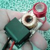
But this is the entry I would like for this first page. This is the Mini ZVS 120 watt induction heater.
Improvements to this module include;
a) The positive power circuit and the control circuit have been separated by cutting the positive trace under the 330nf capacitors.
b) A simple momentary switch, or several in parallel, can be placed anywhere. This is a scavenged switch that is ShoeGoo'd into place. This is wired between the positive input lead and the positive output lead. If you maintain the blue connectors, the positive input lead is now a switch input for the gate circuit; the center pin of the output connector (3-pin) is positive power in put.
c) A 9-turn coil of the original ID and wound closer together raises the resting current about 25%. I need to see what 11-turn coils will change. This one is a little too hot at a 12.6 volt input. I also need to see what axial orientation does to resting current. Oddly enough, orientation is in play, unfortunately.
d) The traces on these boards are woefully undersized. There is one via each on my board to power the source lead of the FET. Therefore I scraped clean the trace between the two S-leads and soldered the 16 gauge negative lead directly to that trace. The via's will power the gate circuit as normal. Same with the positive lead. I wired the 16 gauge positive lead directly to the coil lead.
Result; 5-6 second very hot heat-up on a 19mm coil. It runs about 75 watts at 10.5 volts. I want to raise that 10.5v to 12.6v at this wattage. I'm going to try to do this with the coil alone.
On a cord and a little box, this is a cute little heater.

Reference: IH Bits&Pieces thread
I invite developments as well as builds to participate here to share knowledge and understanding.
Myself, I am in 4 for 4 on home-built Mini ZVS 120W modules. Now that I have some magnet wire, efforts are under way to qualify coils.
My aim is to make a small handheld portable that utilizes a cradle to maintain charge.
...this below ain't it

But this is the entry I would like for this first page. This is the Mini ZVS 120 watt induction heater.
Improvements to this module include;
a) The positive power circuit and the control circuit have been separated by cutting the positive trace under the 330nf capacitors.
b) A simple momentary switch, or several in parallel, can be placed anywhere. This is a scavenged switch that is ShoeGoo'd into place. This is wired between the positive input lead and the positive output lead. If you maintain the blue connectors, the positive input lead is now a switch input for the gate circuit; the center pin of the output connector (3-pin) is positive power in put.
c) A 9-turn coil of the original ID and wound closer together raises the resting current about 25%. I need to see what 11-turn coils will change. This one is a little too hot at a 12.6 volt input. I also need to see what axial orientation does to resting current. Oddly enough, orientation is in play, unfortunately.
d) The traces on these boards are woefully undersized. There is one via each on my board to power the source lead of the FET. Therefore I scraped clean the trace between the two S-leads and soldered the 16 gauge negative lead directly to that trace. The via's will power the gate circuit as normal. Same with the positive lead. I wired the 16 gauge positive lead directly to the coil lead.
Result; 5-6 second very hot heat-up on a 19mm coil. It runs about 75 watts at 10.5 volts. I want to raise that 10.5v to 12.6v at this wattage. I'm going to try to do this with the coil alone.
On a cord and a little box, this is a cute little heater.

Reference: IH Bits&Pieces thread


 Never a dull moment in my shop.


 ... this is my interpretation of the "half pint":


