DIY Induction Heater Builds and References

badbee

Well-Known Member
I was not precise. If I connect them without step down converter would I fry the board or it is safe to run it 5-20V?
A standard 12 V ZVS board will almost certainly fail at 20 V. They can survive on voltages lower than 12 but there may be a point where too low of a voltage will kill it as well.
 
Last edited:
badbee,
  • Like
Reactions: Piecho

TankeyPankey

Well-Known Member
Would it be a dumb idea to not have an on/off switch? I'm thinking just plugging it in and I would be simple enough. With my current setup, there's very little chance for me to ever leave it plugged in so I'm not worried about safety in that aspect.
 
TankeyPankey,

TankeyPankey

Well-Known Member
I use the plug as a switch. I have a small heater that I plug a 3S lipo pack into. Unplugging it makes it safe.
Yeah that was kind of my thought. I could save money/wiring hassle on just plugging and unplugging the IH, which I'd be doing anyways for how I plan to use it.
 
TankeyPankey,

Gomaruana

Well-Known Member
I'm going to make a disclosure here that is for posterity.

It has come to my attention that an invention of mine has been deleted from the public Dynavap Discord. With the crap that is going on on Reddit, this is mine to make public.

There is discussion on how to make a MOD box recognize a ZVS circuit.
I am suggesting that a delay to the second FET gate input resistor would allow for a larger pulse for a MOD box to recognize a ZVS induction heater. The idea is that the delay would allow oscillation to be delayed to allow a higher amplitude of the initial 'short circuit' by avoiding oscillation for the first series of pulses, to manage an appropriate peek load in the pulse time of more mainstream MOD power supplies for 510 connections to ZVS induction heaters.

I want to make damn sure that everyone knows this is my invention as of before this day on 2/9/2023, and of the time this information was shared on the bDynavap Discord and subsequently deleted, and it is therefore mine to put in the public domain for anyone to consider. The device recommended for this operation is a : LTC6994 a one shot delay chip. It will need a 3.3V regulator. Looking forward if someone wants to try this.

If a claim is made on this invention, I expect to be named as part of the invention, period! This is my public notice.
Awesome stuff !

I'm trying to build a higher powered version that is very reliable for desktop use with the anvil vape.
Do you have any ideas on how I could achieve such a build?
Currently I'm running the standard zvs board with a 12v 10a power supply and I use a high power mosfet 5-36v 15a + arduino + temp sensor to do pid temp control.

I've been running that setup for over a year now, but I think the performance has degraded over time, do you think that is possible? Or is it violent failure or no failure with these zvs boards? I've left the power to the zvs board on for too long by accident / my hot-anvil-detection algorithm misfiring. I also think I've seen smoke come out of the zvs board on occasion, but I might have imagined that :ko:
 

TommyDee

Vaporitor
Hey @Gomaruana , the capacitor(s) could degrade over time. The standard ZVS circuit layout is extremely robust. It takes a lot to kill it.

The only smoke I've ever seen come from the components is from particles of flower or condensed oils around the coil.

There are two types of degradation, however; 1) Over-use of a specific components and 2) Different vapcaps. Some vapcaps you simply cannot push a lot of power into where other caps will rail the supply current. Measure the voltage at the ZVS board and monitor this for changes.

If you are running batteries, check that cells aren't changing their internal resistance. I have some end-of-life cells that have a huge voltage drop when firing.
 

Gomaruana

Well-Known Member
Hey @Gomaruana , the capacitor(s) could degrade over time. The standard ZVS circuit layout is extremely robust. It takes a lot to kill it.

The only smoke I've ever seen come from the components is from particles of flower or condensed oils around the coil.

There are two types of degradation, however; 1) Over-use of a specific components and 2) Different vapcaps. Some vapcaps you simply cannot push a lot of power into where other caps will rail the supply current. Measure the voltage at the ZVS board and monitor this for changes.

If you are running batteries, check that cells aren't changing their internal resistance. I have some end-of-life cells that have a huge voltage drop when firing.
I'm wondering if I can remove some wraps and cut off some of the standard coil wire length to get more power out of it?

Edit;

I found out where the smoke came from, it was from the power screw terminals on the zvs board that where a bit loose from the daily use probably.
The wire insulation was a bit blackened and the wire itself doesn't look very fresh any more.
 
Last edited:
Gomaruana,

TommyDee

Vaporitor
Less coil wire length will increase the power draw. Also, be sure to solder the coil to the board. Those blue terminals are the cause of most ZVS module failures. Once soldered, these circuits are very tough.

By making the heater hotter for weak caps can cause an issue if you ever put in a very hot cap. Just a warning.
 
TommyDee,

Gomaruana

Well-Known Member
Less coil wire length will increase the power draw. Also, be sure to solder the coil to the board. Those blue terminals are the cause of most ZVS module failures. Once soldered, these circuits are very tough.

By making the heater hotter for weak caps can cause an issue if you ever put in a very hot cap. Just a warning.
Thanks for the info! I have soldered the coil and will be shortening it and soldering again as an experiment for my anvil.

Do you know by any chance what the difference is between led power supplies and switching power supplies? I'm wondering if I can use this 24v 400w one in combination with a 24v ZVS to get insane heating performance. (For this project I'm heating up a metal part with at least 4 times the amount of metal compared to an anvil)

 
Gomaruana,

TommyDee

Vaporitor
For a higher voltage ZVS, sure. A 400 watt Anvil heater would be something. Possibly a next generation solutions ;]
 
TommyDee,
  • Like
Reactions: Gomaruana

Gomaruana

Well-Known Member
Looking forward to reading about the results.
I've melted the terminals to the induction coil and the power supply doesn't seem to be able to keep up with the heater after I soldered the coil on.
I think the coil was also mismatched with the ZVS board. I used a modified coil from the smaller 12v zvs boards.

Back to the drawing table.
 
Gomaruana,

Vapologe

Member
Help me with my DIY IH

I built an induction heater powered by 2 18650 batteries. I used wiring diagram from vapoven.
Somehow the power is very weak, the Dynavap heats up very slow. Too slow to use it.
Can anybody tell me what could be the reason?
Btw I’m a total noob in electronics…

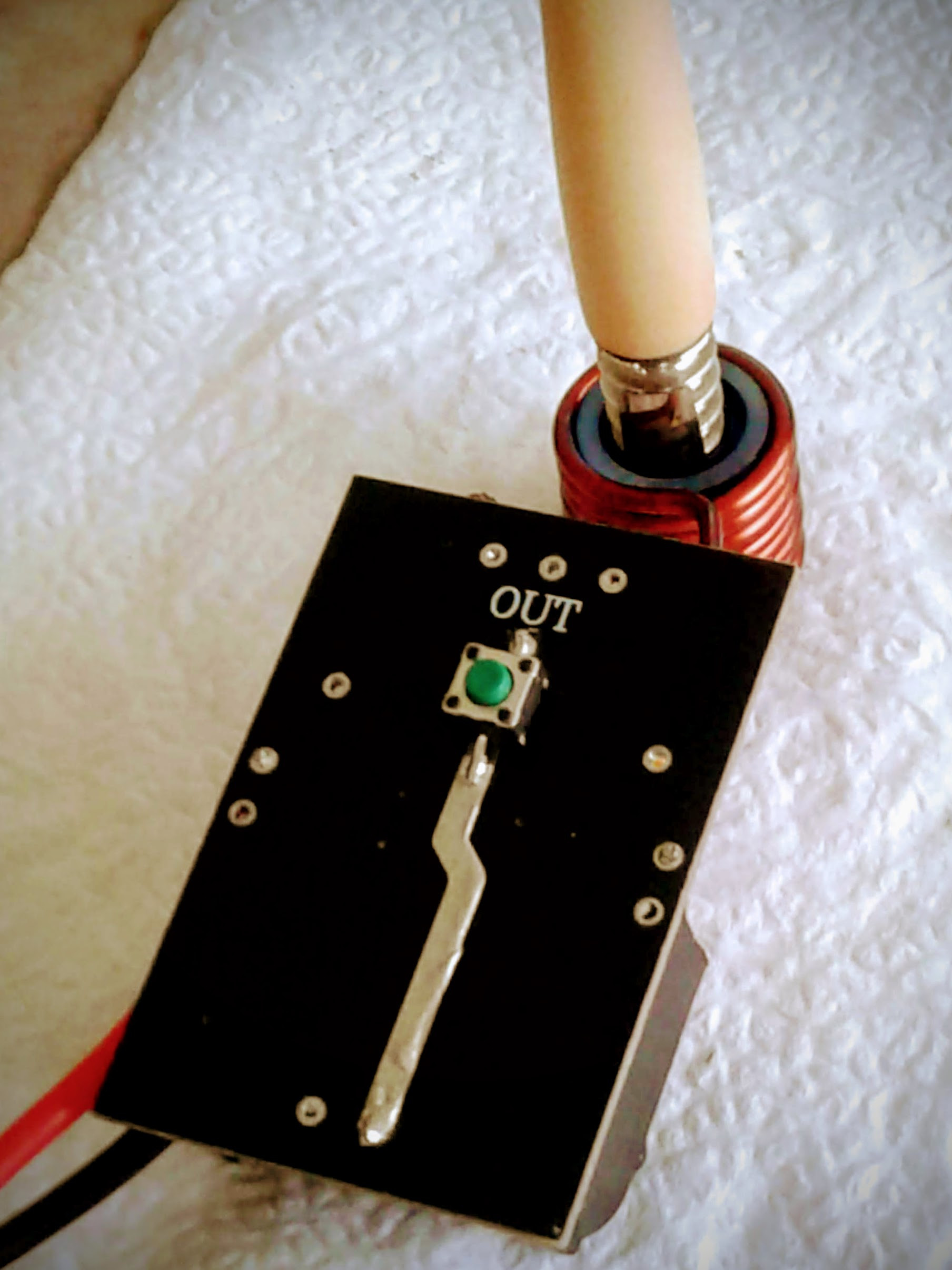
Here is a picture of my build:

Legend for the picture:
1 batteries
2 induction heater
3 momentary button
4 MOSFET (not visible)
 
Vapologe,

TommyDee

Vaporitor
I have not done it but this method should explain my concept for 2-cell IH's:

The coil wire length, not the number of turns, is what what determines the power draw when a vapcap is inserted. Original wire length of the coil is ~33" for a 3S solution. This normally operates at around 10.5V (to the module) at maybe 6 amps to come up with about 63 watts of power to the cap. To reduce the voltage down to 6-8.4V, you need to remove some coil wire length - 33" for 3S does calculate to 22" of coil wire length for 2S.

Do know that to reach that 60 watts, you will be putting more current through the circuit, maybe even 10A at 6V LBV or 7.2V @ 8.33A at nominal.
 

Tauwer

Member
Hi, Long time lurker just wanted to show off the abomination I made called the Jankheater. It's held together by electrical tape.

It's a half mod, 3s with the standard bms and it can be charged with USB C. Tested it out this weekend and it works fine if I heat it a bit past the click.

 
Tauwer,

expremiental

New Member
Hi all!
iam working on custom IH/stash/case/holder for Dyna and stumbled upon electronics. Planned to use ZVS but the opened my YLL 2.0 and found out its build different, like night and day electronic wise.
So now iam looking for a person to chat about IH modules schematics and stuff. iam no electric engineer : (
 

badbee

Well-Known Member
Hi, Long time lurker just wanted to show off the abomination I made called the Jankheater. It's held together by electrical tape.

It's a half mod, 3s with the standard bms and it can be charged with USB C. Tested it out this weekend and it works fine if I heat it a bit past the click.

The first rule of engineering is: if it works, it works.
 

Gr1nse

New Member
I have not done it but this method should explain my concept for 2-cell IH's:

The coil wire length, not the number of turns, is what what determines the power draw when a vapcap is inserted. Original wire length of the coil is ~33" for a 3S solution. This normally operates at around 10.5V (to the module) at maybe 6 amps to come up with about 63 watts of power to the cap. To reduce the voltage down to 6-8.4V, you need to remove some coil wire length - 33" for 3S does calculate to 22" of coil wire length for 2S.

Do know that to reach that 60 watts, you will be putting more current through the circuit, maybe even 10A at 6V LBV or 7.2V @ 8.33A at nominal.
Hi folks,
Hi TommyDee,
Can you explain me what i can do with the heater work coil and how it changes the performance?

So adding length reduces my power draw while taking same time to click?

So reducing length increases my power draw while taking same time to click?

more turns = faster heating and this does what to the circuit?

Lesser turn?

What do the double or triple coil windings? can I count them as normal or does the further distance to the dyna change anything?

the turns better centered on the heating spot allows to better adjust the aggression of the heater?

what can I change by adding or removing coil diameter?

what does a change of the wire diameter?


what is not "good" to modify or change? Something to keep in mind?

What is your most favourable workcoil and why?


then to your halfpint:

what does the reducing of the capacitor and the smaller coil core do to the circuit?

what happens if I reduce the capacitor and keep the coils like before... How does this change the circuit and the performance?


what other capacitor options are there?(looking into further miniaturization...)


And finally what is the best way to get a own insertion sensing?

what sensors can I use near the work coil with out damaging them?


oha that where quite a lot of questions

thank you very much for all your efforts amazing thread!
greetings
Gr1nse
 
Gr1nse,

TommyDee

Vaporitor
Hi folks,
Hi TommyDee,
Can you explain me what i can do with the heater work coil and how it changes the performance?

So adding length reduces my power draw while taking same time to click?
Click would take a little longer
So reducing length increases my power draw while taking same time to click?
The click would come a little sooner
more turns = faster heating and this does what to the circuit?
Number of turns seem to have less effect
Lesser turn?

What do the double or triple coil windings? can I count them as normal or does the further distance to the dyna change anything?
The multiple layers is simply to use the complete wire length
the turns better centered on the heating spot allows to better adjust the aggression of the heater?
The ingress depth moves the clicker further from the sweet spot. This delays the click allowing more heat to build up
what can I change by adding or removing coil diameter?
Proximity to the cap. Very forgiving parameter
what does a change of the wire diameter?
Increases the voltage and risks blowing FETs
what is not "good" to modify or change? Something to keep in mind?
Lots of freedom here. You are limited to 120 watts
What is your most favourable workcoil and why?
20mm long by 16mm ID has the best heating profile along the cap.
then to your halfpint:

what does the reducing of the capacitor and the smaller coil core do to the circuit?
The capacitor is what provides the 'punch'. 2 capacitors is a little too much for our purposes heating a traditional vapcap
what happens if I reduce the capacitor and keep the coils like before... How does this change the circuit and the performance?
The bake is slowed a bit. This allows for more custom heating profiles by giving it 'another second' without combusting.
what other capacitor options are there?(looking into further miniaturization...)
There are a lot of foil-wound capacitors. If they are the wrong ones, they heat up. See what Dynatec and Ispire uses.
And finally what is the best way to get a own insertion sensing?
I would think something like induction sensing at red lights would be the simplest method. That is what the dental heaters use.
what sensors can I use near the work coil with out damaging them?
Best bet is to use the coil itself. That is what Ispire does.
oha that where quite a lot of questions

thank you very much for all your efforts amazing thread!
greetings
Gr1nse
Thanks @Gr1nse . Basically you have two adjustments with the cap itself... ingress depth determines the delay of the click. Deeper ingress means hotter bake. And the second is wattage. Everything about the IH is the rate at which you pour power into the cap, which in turn heats the tip. My sweet spot for heating my '18-M is 60-70 watts. At 80 watts or more, I get a lot of reclaim and low production of vapor. I rate my tune by how crimson red my reclaim is. If the reclaim is runny blonde, the heater is too hot.

One trick to consider is that each turn of the coil is about 1V. Meaning that a 10 turn coil will work great with 10V (roughly). Removing (and shortening) one turn will make the heater act the same as 10 turns/10V using 9 turns and 9 volts. That is my analogy - 33" of 12 gauge magnet wire is for 12V and 22" of 12 gauge magnet wire is good for 8V... Or 33" for 3S and 22" for 2S.
 

132ikl

Member
My work in progress induction heater:
img20240606211754.jpg
img20240606211832.jpg
img20240607184312.jpg


Electronics are outside the box for now until I get around to placing a Digikey order for panel mount buttons and switches. Put together a little RC circuit which is connected to the gate of the MOSFET so I don't have to hold the button the whole time :p Right button charges the capacitor and left button discharges (so I can stop heating manually if the Dynavap clicks before it finishes discharging). Using a 100μF cap in parallel with 200kΩ to keep it high for ~20 seconds. Also have two 1k resistors (in parallel) between the discharge button and ground to prevent a short (not sure what these resistors are rated for so I made sure to keep the max power dissipation under 125 mW just in case).

Thank you @TommyDee for your detailed posts, they've been super helpful. The induction heater has already been amazing even in this state, but I'm a bit stumped on the power usage. The maximum amperage I can get through the ZVS module is around 2.5A, which is seemingly a lot lower than other folks in this thread have gotten. At idle it draws about 1.2A which seems correct, but 2.5A under load seems really low. It takes about 20 seconds to click which is a lot longer than most people in this thread it seems. I previously had a looser wrap on my coil and was seeing around 3.4A max, but it took about the same amount of time to click then as it does now, so maybe the higher power usage was just due to heating up a larger volume compared to now? I also tried bypassing the rest of my circuit and just wago'ing my power supply (12V6A) directly to the induction module and got similar results. Do you have any tips on how to get more heat into the Dynavap?
 

TommyDee

Vaporitor
@132ikl - Your low power draw may be your cap. The weakest cap I ever had came in at around 2.5 amps on a M'20. Also check the voltage at the input of the module to see you have at least 10V. The way you make the power level a bit higher is to remove a loop from the coil. Of course, winding the coil tighter might also improve the coupling.

Don't worry too much about the slow bake. You are reaping the benefits of a better bake as well. But you do want to bake at around 60 watts.
 
TommyDee,
  • Like
Reactions: 132ikl
Top Bottom