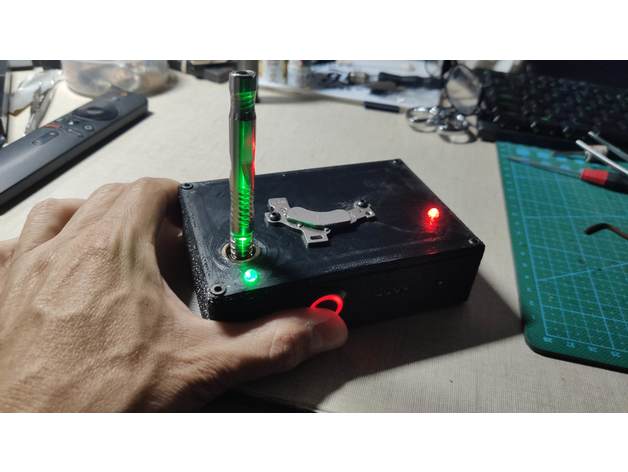
Hi all. So I just finished building my own induction heater using the same design that kent1146 made to make his. I've tried looking at the supplies that were needed and I looked at his pictures on his imgur and his design notes. And even after spending a lot of time looking at his design notes, there was still a lot of things that I didn't understand. I've tried messaging him on Reddit asking him if he could explain in greater detail how it all works and he never responded. So I had to go on Discord and ask for help. So what I did was I took his design and improved upon it a bit. Put in a DPDT On-Off-On switch, added two 30v 1a DC input jacks, one of them for charging a 3s 18650 battery pack and another that allows for using an external power supply/power brick option. The design also allows for you to use the induction heater while it's charging the batteries. There is a blue LED that lights up only when it is on battery powered mode. One side of the switch goes to battery powered mode, the other is for the power brick option. For the external power supply, you can use one that goes up to 12v, but no more than 1a. I like to use exactly 12v, but it's approximately more like 11.8, 11.9v. I also added a mini DC voltmeter in there. Initially, I had trouble figuring out where to add the voltmeter because there wasn't any room on top of the cap. So I decided to add it to the side of the cap and I think it worked out pretty good. The voltmeter lets you know what the battery charge/voltage level is at. The BMS I used is kinda crap because it actually charges the battery over 12.6v. It went up to 13.25v and when I tried to use the IH, it actually shorted out the mosfet board and the IH board, so I had to replace the mosfet board and the IH board. The IH board is only rated for 5-12v, so I have to keep a close eye on it as it's charging the batteries, make sure it doesn't go over 12v. One flaw with the design is that the voltage only turns on when the momentary push button is pushed. Once it's released, the voltage turns off. So the only way to know the charging level/voltage is to push the momentary button. It usually takes me at least 7-15 minutes before I see a significant bump in the voltage going up, but I may have to wait a little longer. That's why I have to keep a close eye on it as it's charging and make sure I don't overcharge it.
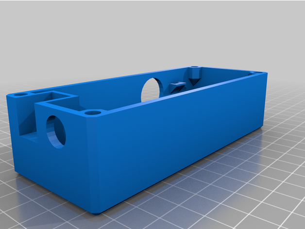
Here's the diagram/design I made for it.

One thing you'll notice on the mosfet, the only thing that's soldered underneath the board is for the wires from the tactile switch/momentary push button switch and from the green LED. Those are all spliced together and soldered underneath. And then we have positive wires from the tactile switch/momentary push button switch and from the COMs terminal on the DPDT switch, they're all spliced together. I actually just spliced all 3 wires together and added a single wire there, make it easier to insert into the terminal of the mosfet and screw them in. The wires for the voltmeter and IH module are spliced together and just inserted into the VOUT side terminals and screwed in. For the blue and green LEDs, I'm using 20K ohm resistors. For the DPDT switch, I just put all the negatives on one side and the positives on the other side.
I used 18 awg stranded copper wire for everything. I went with 18 awg because I was told it's the perfect size to hold the amount of heat that the IH generates. It was a little bit bigger and a little harder to work with compared to 20 or 22 awg, but I made it work.
For the 4oz fruit cup container, I cut off the bottom portion of the container. Then what I did was I took another fruit cup lid, dremel'd out a rectangular piece, then used epoxy to glue it underneath the container. Then I attempted to cut out rectangular or square pieces from another lid and tried to epoxy and glue them to that container. That way, the wires would fit in perfectly and the top of the battery pack sits underneath the barrier and secures it in place. This will act as an extra layer of protection so the battery pack and the IH board don't short each other out. Later on, those square pieces didn't hold up very well, so I just took them off and left the plastic barrier, so I felt that was good enough for me. I also dremel'd out holes on the container for the input side of the IH board for the wires and also dremel'd out the lid on the container and also on the container itself so that it would allow the IH coil through. For the IH coil, I had to cut off pieces from another IH coil and then what I did was I soldered those pieces with the other IH coil, which was a little difficult, but managed to get it done. This is so I could extend the legs of the coil and I could bend them and solder them to the silver surface pads. I had to drill a hole on the lid big enough to get all the wires on the cap through/inside the container and have them go down to where they needed to be. I drilled the hole on the left side to where I mounted the IH board. I used hot glue to mount the IH board upside down and I had to use a lot of hot glue under the capacitors and around them to secure/mount it in place. Then I had a cut up piece of cork, inserted it under the glass slide, then used electrical tape to secure it in place and also positioned the cork in a way so it wouldn't get burnt by the coil.
For the tumbler cap, I designed it in a way in which the DPDT switch and the momentary push button switch were at least 10-15mm away from the glass slide because I had concerns about the coil getting hot and potentially melting/destroying the wires. For the glass slide, momentary push switch, DPDT switch, and voltmeter, I used a DIY hot knife to cut those holes out. For the DC input jacks and blue and green LEDs, I drilled them out. For the tactile switch, I drilled 1mm holes using a handdrill to insert the terminals and then hot glued it and used epoxy to secure it in place. Also used epoxy to secure the voltmeter in place. Also used zip ties to bring the wires away from the coil and secure them in place. And also used 3M electrical tape to cover up the mosfet once it was fully wired up, that way it doesn't get shorted out by the battery pack.
When I finished everything, I tried to push everything down the tumbler, but it was getting stuck, so I decided to cut out the bottom part of another tumbler with the DIY hot knife. Put everything through there, snapped the lid, and slide it through another tumbler, then secured everything in place with 3M electrical tape. This way it gives more room for the 3s 18650 battery pack, IH board, plastic container, and wires because the wires I used were a little too long.
For the 3s 18650 battery pack, I used Samsung 25R 18650 2500mAh 20A Battery, fish paper, kapton tape, silicone caulk, silicone caulk gun, hot glue, battery insulator rings for the positive cells, nickel strips, and a portable spot welder. Then used double sided tape to secure/mount the BMS to the battery pack. I used 3M electrical tape to cover up the bottom of the battery pack, just to give it an extra layer of protection. I used fish paper because I think it looks more professional. Also with fish paper, it holds a low amount of heat, but provides better abrasion protection. Always spot weld nickel strips to the battery pack first before you solder leads there. Don't solder directly to the battery pack because it won't be able to handle the load and you can easily ruin the battery pack and they could end up exploding and you'll have a huge fire.


Let me just say this, kent1146 made it seem like it was so easy to make, but it reality it was actually very hard to make. I thought the drilling and hot knifeing of the holes and constructing the plastic container were hard enough, but I think probably the hardest part was soldering the wires. It was a process that started back in January and took me basically 4 months to complete it, and I wanted to get it done earlier, but I kept running into problems and work was eating up my time. Anyway, everything works now. I hope the design can be used to help you design and build your own DIY induction heater. When I have the vapcap in there, it usually takes about 15 secs before I heard the first click, followed immediately by a loud second click. But even though I heard the second click, the vapcap wasn't ready, so I had to leave it in there a little longer, usually 10-20 more secs after the second click until I see the vapcap start smoking. And then that's how I know it's ready. And able to get multiple drags on it.
Reposted it here because I wasn't sure if I should have posted it here instead.
Here's the diagram/design I made for it.
One thing you'll notice on the mosfet, the only thing that's soldered underneath the board is for the wires from the tactile switch/momentary push button switch and from the green LED. Those are all spliced together and soldered underneath. And then we have positive wires from the tactile switch/momentary push button switch and from the COMs terminal on the DPDT switch, they're all spliced together. I actually just spliced all 3 wires together and added a single wire there, make it easier to insert into the terminal of the mosfet and screw them in. The wires for the voltmeter and IH module are spliced together and just inserted into the VOUT side terminals and screwed in. For the blue and green LEDs, I'm using 20K ohm resistors. For the DPDT switch, I just put all the negatives on one side and the positives on the other side.
I used 18 awg stranded copper wire for everything. I went with 18 awg because I was told it's the perfect size to hold the amount of heat that the IH generates. It was a little bit bigger and a little harder to work with compared to 20 or 22 awg, but I made it work.
For the 4oz fruit cup container, I cut off the bottom portion of the container. Then what I did was I took another fruit cup lid, dremel'd out a rectangular piece, then used epoxy to glue it underneath the container. Then I attempted to cut out rectangular or square pieces from another lid and tried to epoxy and glue them to that container. That way, the wires would fit in perfectly and the top of the battery pack sits underneath the barrier and secures it in place. This will act as an extra layer of protection so the battery pack and the IH board don't short each other out. Later on, those square pieces didn't hold up very well, so I just took them off and left the plastic barrier, so I felt that was good enough for me. I also dremel'd out holes on the container for the input side of the IH board for the wires and also dremel'd out the lid on the container and also on the container itself so that it would allow the IH coil through. For the IH coil, I had to cut off pieces from another IH coil and then what I did was I soldered those pieces with the other IH coil, which was a little difficult, but managed to get it done. This is so I could extend the legs of the coil and I could bend them and solder them to the silver surface pads. I had to drill a hole on the lid big enough to get all the wires on the cap through/inside the container and have them go down to where they needed to be. I drilled the hole on the left side to where I mounted the IH board. I used hot glue to mount the IH board upside down and I had to use a lot of hot glue under the capacitors and around them to secure/mount it in place. Then I had a cut up piece of cork, inserted it under the glass slide, then used electrical tape to secure it in place and also positioned the cork in a way so it wouldn't get burnt by the coil.
For the tumbler cap, I designed it in a way in which the DPDT switch and the momentary push button switch were at least 10-15mm away from the glass slide because I had concerns about the coil getting hot and potentially melting/destroying the wires. For the glass slide, momentary push switch, DPDT switch, and voltmeter, I used a DIY hot knife to cut those holes out. For the DC input jacks and blue and green LEDs, I drilled them out. For the tactile switch, I drilled 1mm holes using a handdrill to insert the terminals and then hot glued it and used epoxy to secure it in place. Also used epoxy to secure the voltmeter in place. Also used zip ties to bring the wires away from the coil and secure them in place. And also used 3M electrical tape to cover up the mosfet once it was fully wired up, that way it doesn't get shorted out by the battery pack.
When I finished everything, I tried to push everything down the tumbler, but it was getting stuck, so I decided to cut out the bottom part of another tumbler with the DIY hot knife. Put everything through there, snapped the lid, and slide it through another tumbler, then secured everything in place with 3M electrical tape. This way it gives more room for the 3s 18650 battery pack, IH board, plastic container, and wires because the wires I used were a little too long.
For the 3s 18650 battery pack, I used Samsung 25R 18650 2500mAh 20A Battery, fish paper, kapton tape, silicone caulk, silicone caulk gun, hot glue, battery insulator rings for the positive cells, nickel strips, and a portable spot welder. Then used double sided tape to secure/mount the BMS to the battery pack. I used 3M electrical tape to cover up the bottom of the battery pack, just to give it an extra layer of protection. I used fish paper because I think it looks more professional. Also with fish paper, it holds a low amount of heat, but provides better abrasion protection. Always spot weld nickel strips to the battery pack first before you solder leads there. Don't solder directly to the battery pack because it won't be able to handle the load and you can easily ruin the battery pack and they could end up exploding and you'll have a huge fire.
Let me just say this, kent1146 made it seem like it was so easy to make, but it reality it was actually very hard to make. I thought the drilling and hot knifeing of the holes and constructing the plastic container were hard enough, but I think probably the hardest part was soldering the wires. It was a process that started back in January and took me basically 4 months to complete it, and I wanted to get it done earlier, but I kept running into problems and work was eating up my time. Anyway, everything works now. I hope the design can be used to help you design and build your own DIY induction heater. When I have the vapcap in there, it usually takes about 15 secs before I heard the first click, followed immediately by a loud second click. But even though I heard the second click, the vapcap wasn't ready, so I had to leave it in there a little longer, usually 10-20 more secs after the second click until I see the vapcap start smoking. And then that's how I know it's ready. And able to get multiple drags on it.
Reposted it here because I wasn't sure if I should have posted it here instead.
Last edited: