DIY Induction Heater Builds and References

Abysmal Vapor

Supersniffer 2000 - robot fart detection device
And......this......
gx7698do2ji81.jpg
That looks intriguing. Where did you get it from "?
 
Abysmal Vapor,

TommyDee

Vaporitor
Is the positive 12V making it into the choke at the center tap? LEDs are over rated. Use a current meter to know what the module is doing.
 
TommyDee,

ploooopp

Well-Known Member
Is the positive 12V making it into the choke at the center tap? LEDs are over rated. Use a current meter to know what the module is doing.
Unfortunately dont have a current meter but I'll pick one up tomorrow, I'll just keep licking it to see where the current goes. Yes, the 12V+ goes to the choke
 
ploooopp,
  • Like
Reactions: TommyDee

TommyDee

Vaporitor
I think "the whole thing' needs definition. Spice the current probe in one of the input lines. See if the circuit is drawing power, and if so, how much. A properly working ZVS, including HalfPint, is around 1.5 amps at 12V. Remember to use the "10A" probe connection to the meter if present.
 

GI

Well-Known Member
Hi,
it's possible that my halfpint click the dyna in less than 8 second ? should be more or not ? or since i try with a 2019 M maybe heat fast ?
Then is dangerous to try use a modbox for aliment a ZVS or at lest doesn't work at all ?

EDIT: whit a 2020M 4 second first clik....with 12v 6A i read that should be more slow i'm right ? what's is wrong ?

EDIT: Sorry my fault, the cap was not the right deep, less, the zone where heat more it's in the middle of the coil, it's right ? but i get 5/8 second, it's possible to heat more slow ?
 
Last edited:
GI,

GI

Well-Known Member
The very best way to know what your IH is doing is to read the current it is drawing with a meter. You want to draw 60-70 watts for a nice calm bake. At 80 watts, you start to loose vape to condensing on the walls of your device. All caps act differently in the IH.
So i can read Ampere and then adjust, volt, coil length ? How i can tune it, i would like a slow heat....about 20 second from cold
 
GI,

Green Kiwi

Well-Known Member
My experience is like @TommyDee , more than 80 watts is too much.i actually found that my preferred power is 45/55 watt is.(close to the Wand I believe?)
I just build a current meter permanently in the unit so I can always see what is is doing.
I tuned the unit down with a piece of thinner wire to the switch under the bowl.
Otherthing very important(just like in real live:brow:)is the depth of penetration.
My tip on the switch pussed down is 4 mm below the lowest winding of the coil.
Also how dense or more spread out the coil makes a difference .

I hope this makes sense @GI , I found the playing around with it much much fun. and always good to have an excuse to medicate the whole day while trying out....:freak:.

Last thing I am very grateful for the time and effort @TommyDee ,has put in this tread and helping people.
over time I read the whole tread, and that really inspired me to give it a go.
Thank you Tommy:clap:.
 

TommyDee

Vaporitor
So i can read Ampere and then adjust, volt, coil length ? How i can tune it, i would like a slow heat....about 20 second from cold
The easiest way to tune an IH is to change the input voltage. Some kind of DC-DC converter or a variable voltage power supply. It will still vary depending on the cap, but voltage control does give you dynamic tuning.

As to tuning the build, I do count on the coil to fine tune the bake rate. Tuning for batteries is a lot harder than a fixed supply voltage. You have to remember the full voltage range of the cell's cycle. Each cell going from 3V to 4.2V. Compromises are made to accomplish this, especially if you have a diverse cap collection.

More 12 gauge wire means lighter load. Basically, it depends on the wire length. Stock length is 33". I suspect a larger coil ID will help tame the heat rate some as well.
 

GI

Well-Known Member
Thanks i have a variable dc but it's 5A so i can check the ampere of my caps one 2019M, two 2020M and 2021M rosium, that don't go over 5A.
If a low the voltage what do the ampere ?
I have the coil modified like halfpint with 3 round outside, should resolder the original ?
 

TommyDee

Vaporitor
Coils are a wonderful adventure in themselves. The larger the ID, the less sensitive the ingress depth is. Also a handy way to dole out more wire.

Yes, as voltage decreases, current decreases. If you are after 50 watts, which is a calm oven similar to the Wand, 5 amps at 10 volts is perfect. If it draws 4.1 amps at 12 volts, who's the wiser? The variance in these calculations may be a single turn of the coil. If you have a stock coil on hand, I recommend using it as a baseline. You might find yourself liking it a lot.
 

GI

Well-Known Member
Coils are a wonderful adventure in themselves. The larger the ID, the less sensitive the ingress depth is. Also a handy way to dole out more wire.

Yes, as voltage decreases, current decreases. If you are after 50 watts, which is a calm oven similar to the Wand, 5 amps at 10 volts is perfect. If it draws 4.1 amps at 12 volts, who's the wiser? The variance in these calculations may be a single turn of the coil. If you have a stock coil on hand, I recommend using it as a baseline. You might find yourself liking it a lot.
Thanks, i have a standard zvs with only the capacitor off and stock coil.
 

gostavs

Well-Known Member
Accessory Maker
On the half pint trace cut, does it matter where the cut is made? Also the trace is much wider among other differences on my last order of mini zvs boards, is it any different regarding making a half pint mod? TIA TD 🙏🏻
 
gostavs,

TommyDee

Vaporitor
Thanks for asking @gostavs - The trace cut is an optional feature for HalfPint. The cut allows you to disconnect the gate circuit from the device. This means the unit does not oscillate and therefore doesn't draw power.

The fat trace goes from the positive input connector to the junction of the two chokes/inductors. The positive input connector also provides power to the FETs' gate circuit via the 470 ohm resistors. By cutting the trace, the input connector no longer carries the majority of the current - Only the LED and the gate pin on the FETs are being powered with microamps. The high power positive is connected directly to the common of the two chokes when you cut the trace. The trace cut is a convenient place to splice in a low-power momentary switch. Provide positive power to the common of the chokes and use a switch connected to the input positive to activate the device.

Too bad we still cannot post pix. Would save a lot of typing LOL

20200926_115745-jpg.11624


Edit: this is the "Cap as Switch" solution. Positive in and choke's centertap is the pair in the center - the top leg is a contact on the farside for positive - the bottom leg, when shorted with a cap, powers the 'gate circuit'. This is the other side;

20200922_175148-jpg.2877


The left and right pads at the connector holes would have a spring contact of some kind.
 
Last edited:

gostavs

Well-Known Member
Accessory Maker
This is how my latest batch of boards look like, a bit different from the version you have. Any experience with theese? This one with a 10 turn coil fried the mosfets, something I have managed to do many many times over now (hey at least Im hopefully learning something :). I bridged the cut from the "loop" high current input wire to the original positive input. Do the bridge need to be as close to the cut as possible, as you have done in the "cap as switch" version imaged above?


Another thing, does cutting the actual board shorter like this have any negative consequence?


Lastly, when shorting a board and frying one/both fets, can that damage the cap or choke? Was wondering if I need to configure a new spliced choke with cap everytime I short the board to be sure thats not causing problems on the next iteration.
 
gostavs,

TommyDee

Vaporitor
The choke and cap are pretty tough. No need to worry about them. FETs fry most of the time from over-voltage. Being unregulated, the output voltage spikes when the work coil is removed.

Cutting the board like that is perfectly acceptable.

Consider the trace a wire. You can tap into it anywhere.
 
TommyDee,
  • Like
Reactions: gostavs

gostavs

Well-Known Member
Accessory Maker
Ty!
Just fried the fourth board in two days, what the hell am I doing wrong :doh: exploded the mosfets with a loud crack and sparks. Let’s hope the next batch of modules is of the “normal” kind, I’ve had success with them and half pint in the past.
 

TommyDee

Vaporitor
I haven't seen one explode yet. What were you heating when it blew?

Edit: if you have some spare MOSFET switches, you could swap those FETs onto the ZVS.
 

GI

Well-Known Member
In my first ZVS the led don't work, maybe because my desoldering skill....i can put one between the trace cut/switch or other place without the use of a mosfet ? I have little time to test my half pint experiment with a regulable 5A brick. Is possible to add a turnable power to the curcuit and use it with 3s battery ? Stepdown buck converter ?
 

gostavs

Well-Known Member
Accessory Maker
It shorted the second I turned it on, same thing with all the boards from the last batch. Checked the values and looked for shorts with a meter on all circuits before turning on the power. Couldn’t find any errors and the wiring is correct. I’m using a 3S pack with a 40A bms board and new VTC6 batteries. I have a 10A fuse to install when things are working as expected again.
Will try to salvage some fets from around and install in a used zvs that worked before. I’ve only had luck with half pint on the zvs with perforated boards and a thinner trace.

GI: you can use a buck converter on a 3S pack and regulate voltage, but it needs to be able to handle high current. The standard LM2596 won’t hold up. And yes you can add leds to the fire switch, not too many as it’s only about 400mah iirc.
 
gostavs,
  • Like
Reactions: GI

GI

Well-Known Member
It shorted the second I turned it on, same thing with all the boards from the last batch. Checked the values and looked for shorts with a meter on all circuits before turning on the power. Couldn’t find any errors and the wiring is correct. I’m using a 3S pack with a 40A bms board and new VTC6 batteries. I have a 10A fuse to install when things are working as expected again.
Will try to salvage some fets from around and install in a used zvs that worked before. I’ve only had luck with half pint on the zvs with perforated boards and a thinner trace.

GI: you can use a buck converter on a 3S pack and regulate voltage, but it needs to be able to handle high current. The standard LM2596 won’t hold up. And yes you can add leds to the fire switch, not too many as it’s only about 400mah iirc.
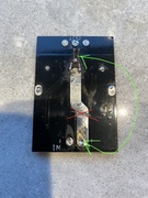
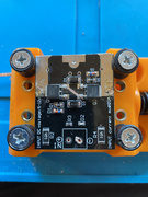
Understand, i have to find a converter capable in Ampere like 12v 10A ? My caps are less than 5A only the 19M go up a little more at 12v. I plan to use for myself or friends with previousaamperage check.
 
GI,
Top Bottom