
-
SCAM WARNING! See how this scam works in Classifieds.
You are using an out of date browser. It may not display this or other websites correctly.
You should upgrade or use an alternative browser.
You should upgrade or use an alternative browser.
DIY Induction Heater Builds and References
- Thread starter TommyDee
- Start date
kokolokokolokon
Well-Known Member
Hello everyone!
I want to share with you some videos i found of dead bug IH circuits wich maybe could be use to build a more efficent and smaller ih.
Two of them are tutorials.
One is a dead bug ih circuit:
The other is the same kind of build (without a premade circuit) but on a board:
The third is just an example of dead bug ih for dynavap with 2x18650:
I think this can be a good way to create a circuit with lower watts (just the amount you need) or even with no need of 12v 5/10a power supply (i dont really know since i have no knowledge about electronics but i see what you do here and maybe you are interested )
)
I want to share with you some videos i found of dead bug IH circuits wich maybe could be use to build a more efficent and smaller ih.
Two of them are tutorials.
One is a dead bug ih circuit:
The other is the same kind of build (without a premade circuit) but on a board:
The third is just an example of dead bug ih for dynavap with 2x18650:
I think this can be a good way to create a circuit with lower watts (just the amount you need) or even with no need of 12v 5/10a power supply (i dont really know since i have no knowledge about electronics but i see what you do here and maybe you are interested
)Schlumbergera
Member
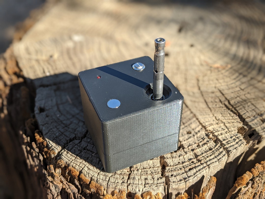
Just wanted to pop in and share the progress with my half pint build. I decided to get a desktop IH going before finishing the SICC, but not just any desktop... it's a half pint!

This thing hits like a dream. I had to figure out the best way to use it though. I set the tip depth so when it clicks, it's ready. At that depth, I get 20 seconds to click from cold, 8-10 warm. The first heat from cold, just a little vapor an the click, but respect them from there on out.
Unwrapped some turns from the stock coil and wrapped them back down the outside. Not sure why, but I'm getting great numbers. At 12V I get 1.2A freewheeling and 2.8A when heating a 20M SS tip w/ captive cap.
Been working on a case this week. Found an antique wooden artists charcoal box on eBay for cheap... sorted through bits and pieces on my workbench until I found all the other parts I needed. Ultimately, there will be a dead bug 555 circuit connected to the knob, for power control. But for now, it's in the case and running! I'll post another picture or two when I finish up.
I'm naming this one Satan's bunghole

@TommyDee
Thanks again for all your research and dedication to furthering the DIY IH. I couldn't be happier with this project and owe you for that.
This thing hits like a dream. I had to figure out the best way to use it though. I set the tip depth so when it clicks, it's ready. At that depth, I get 20 seconds to click from cold, 8-10 warm. The first heat from cold, just a little vapor an the click, but respect them from there on out.
Unwrapped some turns from the stock coil and wrapped them back down the outside. Not sure why, but I'm getting great numbers. At 12V I get 1.2A freewheeling and 2.8A when heating a 20M SS tip w/ captive cap.
Been working on a case this week. Found an antique wooden artists charcoal box on eBay for cheap... sorted through bits and pieces on my workbench until I found all the other parts I needed. Ultimately, there will be a dead bug 555 circuit connected to the knob, for power control. But for now, it's in the case and running! I'll post another picture or two when I finish up.
I'm naming this one Satan's bunghole
@TommyDee
Thanks again for all your research and dedication to furthering the DIY IH. I couldn't be happier with this project and owe you for that.

I like this, how to do this ?
Schlumbergera
Member
I would think that you could wire (2) 18650's to a half pint, add some heat shrink, and have a similar sized portable IH.I like this, how to do this ?
TommyDee
Vaporitor
Nah; they are using an alternate way to resonate with 2 less chokes. This requires a wire at the center of the coil as the positive input. The center-tapped coil now acts as 2 inductors when the VC is present.
They are also using a bare bones minimal capacitor. All energies induced is cumulative so it will eventually click. The Wand puts out 45 watts on a stretch. Always a good bake.
They are also using a bare bones minimal capacitor. All energies induced is cumulative so it will eventually click. The Wand puts out 45 watts on a stretch. Always a good bake.
Schlumbergera
Member

Schlumbergera
Member
Thanks man, I appreciate it. I have the circuit laid out in a simulator so I could get the duty cycle / frequency / component values squared away. Right now I have it set to about 1.3Hz with a minimum duty cycle of 20% and a maximum of 90%. Good call on the LED's, I'll make sure to add a transistor to drive my 'fire' LED's cause I have quite a few in there.
hey did you ever build this? was trying to see if there was any updated but couldnt find any. am also interested in a usb ihHi everyone,
I'm currently planning an IH build powered from USB-PD. I ordered most of the parts I will need, but I wondered if you could provide me with insights if anyone did something similar.
I might try the half-pint circuit, but I'm not sure if the mini-zvs I bought is compatible.
- Power : USB-C Power Delivery. Since it can do 100W, it might work, of course, depending on the power source.
- StepDown 12V : 24V to 12V 10A
- Mini-ZVS
I was also wondering if it's possible to separate the coil from the zvs board.
I have just realized that I don't have a glass tube.
ugotmale
Well-Known Member
I saw this awhile ago on Etsy:
 www.etsy.com
DICE Portable Dynavap Induction Heater batteries Sold Separately - Etsy
This Tobacciana item by Chris3DPrintsUS has 261 favorites from Etsy shoppers. Ships from Yucaipa, CA. Listed on Feb 11, 2024
kokolokokolokon
Well-Known Member
it is similar to the first video i posted, which is a tutorial.I would think that you could wire (2) 18650's to a half pint, add some heat shrink, and have a similar sized portable IH.
i have to say i asked to know how it works with 2 18650 and it last 7 clicks xd
TommyDee
Vaporitor
Try a 7-turn coil (12 gauge) on a 2S with the standard module, cap-reduced module, or a HalfPint module.
Any IH should do much more than 7 clicks with 2S 18650. Remember that the DynaCup was a 2S device and people liked that. I never counted clicks with 3S but 2S will be 2/3rd the clicks. It is simple math. It should push <200mwh per click or <1WH per bowl to the cap for diagnostic purposes.
Any IH should do much more than 7 clicks with 2S 18650. Remember that the DynaCup was a 2S device and people liked that. I never counted clicks with 3S but 2S will be 2/3rd the clicks. It is simple math. It should push <200mwh per click or <1WH per bowl to the cap for diagnostic purposes.
kokolokokolokon
Well-Known Member
Thanks Tommy!Try a 7-turn coil (12 gauge) on a 2S with the standard module, cap-reduced module, or a HalfPint module.
Any IH should do much more than 7 clicks with 2S 18650. Remember that the DynaCup was a 2S device and people liked that. I never counted clicks with 3S but 2S will be 2/3rd the clicks. It is simple math. It should push <200mwh per click or <1WH per bowl to the cap for diagnostic purposes.
i didnt try this kind of circuit yet, no time right now, i just asked on the video comments because of 2s (and i like the battery-module conection xd).But, about 2s, i remember you need 12v and you get around 7s with a 2s. Would solve this a 7-turn coil? (Longer coil=less power you need? I thought the longer coil you have = the less power It takes, but you still need 12v on the module)
TommyDee
Vaporitor
@kokolokokolokon - the voltage, ranging from 5 to 12 volts, these modules use determines the power. It is directly related to the length of the coil wire in our case. 10 turns on a stock coil for 12V is 33" long. If you make the voltage 2/3rd of 12V, 8V, then you can also remove the same percentage from the coil wire for similar operation at lower voltages. 2/3rd of 33" is 22"; approximately 7 turns. The difference is that the current goes up. Say from 6 amps to 9 amps. The power, I*V=W, is all relative. If you can measure the power when heating the VapCap, tune for around 60-70 watts.
I spent a long time optimizing Fluxer's Flite performance. The critical data came in at low battery voltage. I wanted to make sure that at 9V (3S), Flite would still provide functional hits. For 2S, your low voltage limit is 6V. You are still within the window of 5-12V.
I spent a long time optimizing Fluxer's Flite performance. The critical data came in at low battery voltage. I wanted to make sure that at 9V (3S), Flite would still provide functional hits. For 2S, your low voltage limit is 6V. You are still within the window of 5-12V.
badbee
Well-Known Member
Absolutely, that's what a buck is for. You can find high amperage DC motor controllers on EBay and Amazon that will do the job for $15-$20. You can also get a similar effect from using a PWM signal to a driver mosfet. The full buck is overkill for this scenario since the ZVS already has many of the same circuit elements. You can build a PWM controller or buy them.Can a buck converter fix the output voltage even though the input varies(lowers with usage)?
badbee
Well-Known Member
No I haven't, but I've followed the builds of other people who've done it. It seems to work fine. I think so long as you keep the frequency low, say <1 KHz, the mosfets shouldn't spend too much time in their linear range. The cap would need to be pretty big to have an impact but it might reduce stress on the ZVS.Have you tried straight up PWM @badbee ? Seems a holdup cap would do good on the output to keep the FET from actually turning off completely. I have a PWM motor controller here somewhere.
CaleidosCope
Well-Known Member
Hello. New year approaching...new idea... and a new question! ")
Hey TommyDee... what if I separate the coil from the board? Good Idea?!
Two-Wires, 1mm2, 50-100cm length, should do the job. Is this an option?
I was thinking to give the coil a separate housing. Temperature-Controlled.
Possible?
Hey TommyDee... what if I separate the coil from the board? Good Idea?!
Two-Wires, 1mm2, 50-100cm length, should do the job. Is this an option?
I was thinking to give the coil a separate housing. Temperature-Controlled.
Possible?
Last edited: