
-
SCAM WARNING! See how this scam works in Classifieds.
-
The Frolic by Limelight Giveaway is over. Congratulations to the winner: Numerous_Nothing!
You are using an out of date browser. It may not display this or other websites correctly.
You should upgrade or use an alternative browser.
You should upgrade or use an alternative browser.
DIY Induction Heater Builds and References
- Thread starter TommyDee
- Start date
My English is low, can you explain ? In my job i borrd a lot but....If my friends didn't tell me to do stupid stuff life would have been boring up to now.
Not a bad friend, no, but i'm not expert at all, i simply ask....i was think about more useful and long lasting a 3s charge not that 1s is near impossible....then i can't go into a project where i know almost nothing and the success is quite 0....so i try first the 3S or 2S and half pint.....you are the expert teacher :-) ;-)@GI , I wanted to see you experiment with the 1S just so I could see the result. Unfortunately failure and some waste of money was the most likely result... Does that make me a bad friend? Good luck with your project.
About ecig mod boxes, can be possible a fake coil that say ok to the mod box chip to avoid coil sense ?
TommyDee
Vaporitor
You might have something there. One could try a conventional vaping coil or power resistor in parallel to a ZVS. The coil/resistor should allow maximum resistance the mod allows. When the idle power of the IH kicks in, the power will be shared with the coil. It has to reach about 7 volts across the 'bypass' coil to make a ZVS viable. Reduce the work coil to 7 turns/22" for 2S operation.<snip>
About ecig mod boxes, can be possible a fake coil that say ok to the mod box chip to avoid coil sense ?
Hi, can i ask what type of cell are and what BMS is used here ? i like to do the same build.Decided to call this build Artemis, she did kill Orion after all
https://www.reddit.com/r/Dynavap/comments/lwto8a
Probably will have this one done before my 2nd build as I am only waiting on a 15mm dowel to arrive to wrap the coil.

bask
Well-Known Member
18350. The brand is Vapcell.what type of cell
Hi,
I start slowly to transform my first HI experiment in an half pint, this:
EDIT: will be 13,5, the inside of the 14 maybe.
I start slowly to transform my first HI experiment in an half pint, this:
It has one Capacitator and the trace cut, so i look at the inductors, i have to find the center of the wire right ? my is 28 not 31 so how i can do it ?
EDIT: will be 13,5, the inside of the 14 maybe.
Last edited:
I started my halfpint i hope it's right my centre of inductur:
Now i'm at this point, start to buil the 3 leg:
Now i need to pass to the board modification and i think i need some good advice and answer to some poit that i don't have clear in my mind.....
Now i'm at this point, start to buil the 3 leg:
Now i need to pass to the board modification and i think i need some good advice and answer to some poit that i don't have clear in my mind.....
I hope everething it's ok, there's something i can check before fire on ? i have a tester but never used one.....
Hi there,I'd love to see a 1S solution work. That 15-20A draw has to be managed at the converter.
You can do 2S without an inverter. Try removing 3 loops and the associated wire from the coil. A 7 turn coil should make for a good starting point for a 2S heater. The coil will get a little warmer but it should cook at around 60+ watts. Haven't tried one yet but that is the right formula.
A long time lurker showing up.
First, I would like to thank @Pipes and you, @TommyDee for making this induction idea a real thing. You made me to brush my electronics skills but it was very well explained which helped a lot. I updated my gear from the first MOS version to current pint/half-pint and even could built some for friends.
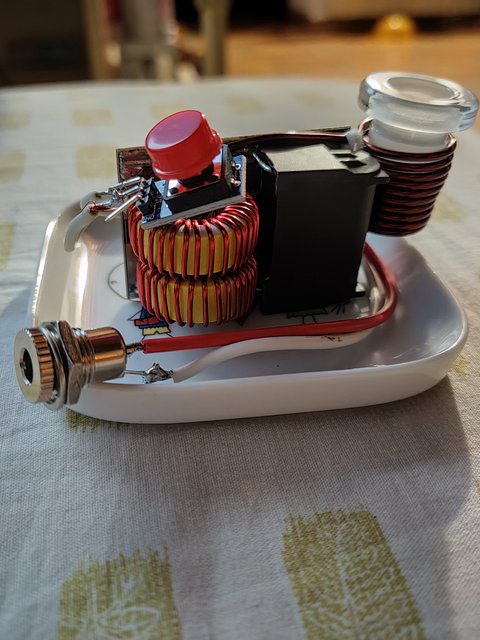
Now, I try to get the thing portable. I would like to share with you my last iteration.
I made this half-pint connected to 2 x 18650 with specs I don't know. There's no BMS for now, I wait for it with some new batteries. I know the risks and I do not plan to use this prototype anymore without it. The coil is made of 8 turns of the original copper, around a 16mm glass.
Fully charged, it clicks a Ti Cap from 25 sec for first click to 32 sec for second click. I reheat usually 10 sec after the cold click, so I measured those times too. It clicks from 15 sec for the first click to 22 sec for the second click with this starting warm temperature. I took measurements for the pictured M too; I need to crosscheck them later.
The coil not even warm after first run and is a bit hot after the 2nd. I suspect that the heat comes from the Cap heating and transferring it to coil thought the glass. I can put a finger on it without being burn but I cannot leave it on.
So far, I ran it about 10 times and the 2S still delivers 8.1V from fully charged ( 8.4V I supposed but I forgot to take the numbers ).
The next step is to add a BMS for protection and use VTC6. I hope those brand new and more powerful batteries will help to lower the heating time. I will change the pint architecture to use + and - pads instead of those 2 cables that are way so closer to the coil for my taste.
Once "stable", there's lot of ways to explore like casing or adding a charging module using USB.
Thanks again for this community.
TommyDee
Vaporitor
You might be up for loosing one more turn from the coil, shortening the wire. I suspect you are running in the sub-40 watt range with your cap. A current reading would be useful but if it takes 25 seconds and you want 15, then removing a turn would be prudent.
Love where this is going. Great work!
Love where this is going. Great work!
Hi, can be this a good option, 3s with soldered BMS ?
https://www.ebay.it/itm/124461683979?hash=item1cfa7e950b:g:KDoAAOSwgKpgRxcW
https://www.ebay.it/itm/124461683979?hash=item1cfa7e950b:g:KDoAAOSwgKpgRxcW
badbee
Well-Known Member
That looks well made and can handle a ton of current, price seems reasonable, so yes.Hi, can be this a good option, 3s with soldered BMS ?
https://www.ebay.it/itm/124461683979?hash=item1cfa7e950b:g:KDoAAOSwgKpgRxcW
I have a powerbank and try to learn how measure ampere, is this the right way ? i connected the tester to the battery positive and then to the circuit positive. Also is the circuit a BMS or only a Charger or both ? on the enclosures say 5000mA / input 5V - 1A / output 5V - 1A, i know that maybe is not suitable for an half pint but i don't know exactly.
Thanks and sorry for my noob questions.
Thanks and sorry for my noob questions.
TommyDee
Vaporitor
You want to be a little careful about current readings. The scale is important. You are on the 20 milliamp scale and that is handled through a device that hopefully limits the current as well. You want to read current on the "10" setting.
Current reading is much like a fuse - you already have it correct, the meter is spliced into the line you want to measure.
You should get readings of about 1-1/2 - 2 amps when no vapecap is inserted but firing (things getting warm). When you drop the cap in the coil, you will get readings anywhere from 5 amps to maybe 8 or 9 depending on the finished circuit and the cap you are using.
Half pint can draw the same power as the full module. At some point there are diminishing returns, say anything over 80 watts total when firing on the cap.
badbee
Well-Known Member
Just to emphasize even more, measuring high currents is the activity most likely to kill your meter. You need to go carefully. The red lead is in the wrong spot, you have to move it up to the socket labelled "10 A - Max". If you measure this current as is there is a good chance of damaging the meter. Like TommyDee mentioned change the scale dial to "10" as well, that is at about the 4 O'Clock position. Also note that these meters are only capable of reading high currents for a few seconds at a time. Never go longer than 10 seconds, or whatever your manual says, give the meter a few minutes to cool off between readings (yes that 5+ A is going through an internal resistor that will get very hot).
Hi TommyDee, Thanks for the work. I call my versions 'A Cup' because its the same volume as a HalfPint but not quite the HP circuit. I don't use the trace cut mod. I like the FET switch for it's clean on and off transition(de-bounce), and plan to use it with PWM to adjust the heat cycle in my next-gen versions. Currently, I manually pulse the power to get the heat in the product where I want it. The OG versions that I built 4 years ago to get into induction heating Dynas are still running strong with the FET switches. As an aside, I think I also get excellent reliability because I have always used 10 amp supplies at the minimum. I have some 3S 18650 supplies with one of the basic Chinese BMS. Like you, I remove the cells and charge them on an Opus charger. For portable use, my A Cups have a 1000maH LiPO inside the box for 20+ heats easily. My portables have a basic LED voltmeter that shows the battery voltage when the fire switch is pressed. No excuse for over-discharging the battery. I think it's worth having an ac powered IH as well as a battery version.
As many have noticed, the new caps don't work nearly as well. However, what we are interested in is the temperature of the product not the cap. To that end I'm interested in finding someone to make glass caps to get away from the DV metal cap altogether. Currently I 'log roll' a capless tip in a horizontal work coil and time the heat; part of my next-gen PWM circuit will be an adjustable timer. The capless technique is a bit fussy and it's easy to make a mess, but heats the tip and product evenly. A glass, or perhaps silicon, cap will keep the product inside the tip and make handling the DV easier. I personally find the OG coil to work best for the even heating I prefer. I have some two layer coils but the insertion depth is too fussy (for me). The voltmeter responds to insertion depth as the induction of the work coil changes with more or less metal inside. Easy to see small differences in depth.
Finally a couple of tips for builders. If you blow a FET and desire to replace it, the first thing is to snip the leads on the dead FET. That way you can un-solder the FET without having to keep multiple solder joints molten at the same time. Once the dead FET is off the board you can clean up the pads, prepare the new FET, and solder each lead in turn. Good soldering is mechanically clean, clean, clean, then flux(chemical cleaning). Second tip is for making the center tap on the inductor. I use a round wooden toothpick, or nylon spudger, nothing metallic, to carefully pry up the center winding I'm going to solder to. Get it up enough that the new wire will pass easily under the loop. Clean the insulation off the raised part and tin the cleaned section. For the wire you are using to connect, I use wire 'harvested' from a removed inductor, clean 3mm of insulation off the end. Bend the end in a horizontal plane so when it goes under the inductor center-coil wire it just shows on the other side. Use smooth pliers to flatten the end and carefully bend 1mm of the end up a little. The wire should end up a bit like a modern ice hockey stick with curved blade. Now when you put the wire under the loop it will 'hook" on to the inductor wire and help to make a good joint. This is the most critical joint in the circuit, so every effort should be made to protect it from mechanical stress. To that end I do not run the wire straight down to the board. I bend a flat loop in the wire, i.e. in the same plane as the circuit board, so that when, not if, the inductor moves, all the stress is not taken directly by the solder joints. Somebody, not you of course, is going to drop the device at some point and that heavy inductor is going to jerk on the solder joints. A little flex in the wire will help. Once you have it all lined up, tin the flattened end of the wire, feed it under the center turn loop, and solder it. I use the far end of that wire, after it passes through the board, to make a loop for connecting the + power to the board and inductor.
Hope that helps and thanks for all your development.
TommyDee
Vaporitor
The BMS has a low voltage cutoff. It is really low, sometimes too low for people's sensibilities. 2.5V is the hard cutoff per cell. That means it will trip before 7.5V on the 3S pack. There is variability in this setting and you would have to test this.
I like this little meter...

The BMS is also a fuse. Sometimes a BMS has to be reset by applying a charger.
I like this little meter...
The BMS is also a fuse. Sometimes a BMS has to be reset by applying a charger.
There is an excellent article on how to prolong the life of Lithium batteries at Battery U. It looks to me that there is a very worthwhile advantage in low depth of discharge (DOD) cycles. Using a 3S Lipo pack I recharge at 11 volts. I get 25+ dyna clicks out of 1000ma/h Lipo from Zippy at that voltage. If there is a need for a few more clicks at the end of a session, I just plug in another battery. They cost less than $8. If you need more clicks every charge cycle, then use a larger battery. At that DOD you should be able to get from 5000 recharge cycles on up. Even at the low end, that is a lot of use. That is with a standard/OG two coil two cap circuit. From 11 volts the battery recharges in minutes not hours. I you use one of those BMS circuits to cut the circuit when it thinks, you are way down the DOD curve. Could be 7.5 volts. I never get that low. By the info from Battery U you will get a greatly reduced number of cycles. I think you really need to know what the actual voltage is to get best use out of the battery. I have used a couple of the individual cell and total battery voltage digital meters. If you short cycle Lipos then the individual cell differences seem to be stable. I decided that as long as I knew the total voltage at that DOD, 11 volts for 3S Lipo, I was good. Discharging below 9 volts for a 3S, I am not sure you can count on the cell voltages not changing.
I think we are in a very good moment with DIY IH's. The development of the Half Pint circuit and layout, and the state of batteries for electric powered airplanes and cars are a happy temporal conjunction; resulting in a very practical device. Image is of a batch a group of friends made this summer. The wood boxes are OG circuit and have been reliable from day one~ 4 years. They are typically wall powered. Still my preferred device for best vapor. I put XT60 connectors on the output of my wall supplies. Its an excellent connector; good for 60 amps, it can take big wire easily, and the good ones are inexpensive. If there is a need for IH movement, and/or having the unit close to hand, we connect a Lipo and rubber band it on; a Strap On. All the others are what I call A Cups-same size as a Half Pint. They all have the FET switch in the circuit, its between the capacitor and the work coil, so they are not true HalfPints. I have gone back to the OG coil. As you can see we made some two layer work coils but I prefer the longer single layer. The clicks are the right length for me and are consistent. I think that is because the field is larger, lower intensity and less focused. One of the basic LED digital voltmeters (~$2)is glued on to the board right next to the switch. Reads when switch is on. No excuses about battery voltage. To make room for the voltmeter is the reason the toroid coil is off center on the board. As you can see from the finished one inside the plastic container, the power wires get trimmed. Mostly I charge through the balance connector with one of the inexpensive Turnigy chargers; not while in use. If I feel like it, I will get out the B6 and balance the cells. So far it has not been an issue. The fuse holder is bulky but I like blade fuses and I won't use a lithium battery without a fuse. I would like to find something just as good in a smaller package. There is room in the 283ml = 1/2 Imperial Pint = 1 Imperial Cup container between the battery and circuit for an M and some product; it's waterproof when the lid is on. A Cup.")

I think we are in a very good moment with DIY IH's. The development of the Half Pint circuit and layout, and the state of batteries for electric powered airplanes and cars are a happy temporal conjunction; resulting in a very practical device. Image is of a batch a group of friends made this summer. The wood boxes are OG circuit and have been reliable from day one~ 4 years. They are typically wall powered. Still my preferred device for best vapor. I put XT60 connectors on the output of my wall supplies. Its an excellent connector; good for 60 amps, it can take big wire easily, and the good ones are inexpensive. If there is a need for IH movement, and/or having the unit close to hand, we connect a Lipo and rubber band it on; a Strap On. All the others are what I call A Cups-same size as a Half Pint. They all have the FET switch in the circuit, its between the capacitor and the work coil, so they are not true HalfPints. I have gone back to the OG coil. As you can see we made some two layer work coils but I prefer the longer single layer. The clicks are the right length for me and are consistent. I think that is because the field is larger, lower intensity and less focused. One of the basic LED digital voltmeters (~$2)is glued on to the board right next to the switch. Reads when switch is on. No excuses about battery voltage. To make room for the voltmeter is the reason the toroid coil is off center on the board. As you can see from the finished one inside the plastic container, the power wires get trimmed. Mostly I charge through the balance connector with one of the inexpensive Turnigy chargers; not while in use. If I feel like it, I will get out the B6 and balance the cells. So far it has not been an issue. The fuse holder is bulky but I like blade fuses and I won't use a lithium battery without a fuse. I would like to find something just as good in a smaller package. There is room in the 283ml = 1/2 Imperial Pint = 1 Imperial Cup container between the battery and circuit for an M and some product; it's waterproof when the lid is on. A Cup.