VapCap DIY Induction Heating : Bits 'n' pieces

PKOK

Well-Known Member
Check out this young mans work on reddit, I'm thinking he got some inspiration from your rig.

https://www.reddit.com/r/vaporents/comments/fjx4uo/r2dday_a_4_minute_long_vapcap_ih_sesh/
I wonder if something similar would work on a Titanium nail.


Let me ask again about that Debouncing circuit. Those that use the tac switch at tube bottom to activate get some sort of distortion in the current. Does a momentary switch do the same or an on/off switch? Is that why I've seen the induction unit in a Faraday cage and the switches in copper tubes? I've got the parts for that card, well except the card.
 
Last edited:
PKOK,

TommyDee

Vaporitor
No need to say 'Hey Boomer!' cause I is one too.

I will admit I never liked having to dismount my cells so as a DIY hobby pack, I don't have an issue with BMS. I did at least check the charging circuit to know it put out 4.2v to each cell. That is easy enough. I also know I can keep my source voltage under 12.6v while charging. And I monitor with a little digital meter. I don't rapid-charge my 18650's.

The meter may be aesthetic. Not sure if anyone has put out a simple green/yellow/red arrangement other that the scooter crowd. I like the little battery looking meter one but real data is worth knowing. I have several of the cheap meters. I haven't arranged anything permanent yet. I do like the idea of simpler though. let's see what the options are.

I have both. My main heater is still the 3x 18650 pack. Working a charm. The resistor charger is the perfect solution. Once every couple of days let it go overnight. It only goes to 12.45v so it will never overcharge. Every 2 or 3 months I'll give the cells a proper cycling. I am counting on the FETs to save a short circuit since I have no fuse. 30 amps through 18 gauge isn't exactly an inferno. And it's plugged into the IH.

The 14500 2S is for the reheater. I want a pack that I can switch from 2S to 3S easily. This creates a charging dilemma. Cells with balance chargers should also have fairly even cells. I'm waiting for yet another IH from China to see if a HalfPint will work as a reheater. I will probably settle on 3x 18500 with a better charging solution.

Oh, the video; notice he's running 2x 18650. But yes - this will go viral once its out. Seriously - the honey realtime heating generates is crazy thick. I get zero satisfaction just drawing the second click of a fresh bowl anymore.

The momentary switch is a hard DC line. No cross talk with the frequency of the IH. Basically, the FET switch is latched High through the gate so it too should be DC. You just need a very good solid connection. Most quality switches don't 'bounce'... send transients through. However, these devices can process PWM signals. That is probably what clashes with an IH frequency.
 
Last edited:
TommyDee,

PKOK

Well-Known Member
Oh, the video; put the cap on dude! But yes - this will go viral once its out.

I think that's a Vap Cap he's using.

I have both. My main heater is still the 3x 18650 pack. Working a charm. The resistor charger is the perfect solution.

Resistor Charger? <- on the 20amp Board? How long have you run one of these induction circuits?

I wonder what the lifespan is on these. I'm in that year long line for that beautiful jobbie a fellow FC member makes, but my Mains version has been working great and it looks pretty good
 
PKOK,

TommyDee

Vaporitor
Yea, just caught that. Looked like raw herb before the video focused.

Also known from days gone by as 'trickle charging'. I have a limited output voltage source that the batteries are balancing to. There is a 5 watt resistor [5 ohm] that makes up the difference between the pack voltage and the charger voltage. A pack down to 9V would be 3.6V different from the wall wart and I say 0.4A/Hr charge rate. 3.6*0.4=1.44 watts. The voltage quickly reaches 10.8V where the charge rate is reduced and the resistor becomes warm to the touch, not hot. As the voltage of the cell nears the charger voltage, the current heads to zero. It can do this indefinitely as long as the voltage doesn't go over 4.2V per cell. A cheap 1A wall wart and a 5W 5 ohm resistor and you have a Li-ion charger for a BMS 3S pack.

Lifespan? It is by all definition a static device. Outside influence is the only 'wear' that can happened to the functional junctions within the devices. The IH FETs are pretty sensitive, but that is because the circuit is 'intense' for lack of a better term. So static shock or wild transients can blow these FET's. I've left it on to make it too hot to tough though. Heat it can handle. Just not good for the user. Hence my insistence about momentary on states.

Going on 3 months? Hell, you got me! As long as I've been vaping from the VC. Its never seen a torch.
 
Last edited:

PKOK

Well-Known Member
Also known from days gone by as 'trickle charging'. I have a limited output voltage source that the batteries are balancing to. There is a 5 watt resistor [5 ohm] that makes up the difference between the pack voltage and the charger voltage. A pack down to 9V would be 3.6V different from the wall wart and I say 0.4A/Hr charge rate. 3.6*0.4=1.44 watts. The voltage quickly reaches 10.8V where the charge rate is reduced and the resistor becomes warm to the touch, not hot. As the voltage of the cell nears the charger voltage, the current heads to zero. It can do this indefinitely as long as the voltage doesn't go over 4.2V per cell. A cheap 1A wall wart and a 5W 5 ohm resistor and you have a Li-ion charger for a BMS 3S pack.

So remember I'm an electrical midget....where is this resistor wired in? Again wouldn't the wall wart wired to a DC-DC Buck Boost Converter do all that and more by being adjustable? Those fancy ones you found
have a lot going on.

Going on 3 months? Hell, you got me! As long as I've been vaping from the VC. Its never seen a torch.

Huh? Lost me buddy :hmm:

Ok off to find an enclosure, I thick I'll use a Hammond Enclosure. I notice they've upped their offerings.
My mains version is in an ABS the problem is the VC cap has left little dings where I bumped it pulling out when hot. So I may do aluminum and spray it with Bed Liner, I did this with a Box Mod and it came out bullet proof, I still have a can somewhere.
 
PKOK,

TommyDee

Vaporitor
Lifespan - These should last forever. I was saying that I never used anything but an IH. I also don't see a lifetime limit.

Bullet proof is a good thing. One day I'll print a case. Without it I just have to be careful about holding keys and the IH in the same hand.

And yes, a boost/buck driver would work perfectly fine as long as you can manage the current. I have boost drivers that have no current limit and buck driver that needs more wall wart than I have.

The resistor choice was a simple formula to understand requirements. V/IR is the only thing us mechanical types need to know to make good choices with regard to electricity. Basically I put a buffer between the batteries and the wall wart. The calculation above is the resulting work the buffer will have to do. For us, simple - smaller wire means more losses from one end to the other. So it you put a meter between the two ends of the wire that is drawing current, you would read a voltage. It is this voltage that defines R in the equation where you have A and V. What we know instinctively as mechanical types is that smaller wire with more current generates heat. Waste heat is the subject matter at hand. I want to flare off the extra energy in the charge circuit through the resistor which limits the circuit's current draw by way of the modified circuit impedance. The modification was to add a resistor reducing impedance. Impedance is just the direct, or indirect 'resistance or virtual resistance' of a circuit. That is simplified by spades but in general, it is an easier way to think of this.

Virtual resistance here just means that a static ohm meter reading will not be accurate. The IH is such a device. It has impedance (acts like a resistor) but reads a much higher resistance then when the device is operating.
 
Last edited:
TommyDee,

PKOK

Well-Known Member
don't see a lifetime limit.

Really!
That is good to hear.
I fried my first module so it put me on the fence with them but more than likely I did something
stupid or had a bad module (I didn't check the solder joints) because like I said the 2nd build has been
kicking ass.

And yes, a boost/buck driver would work perfectly fine as long as you can manage the current. I have boost drivers that have no current limit and buck driver that needs more wall wart than I have.

You should't have shown me the packaged ones, I think the're cool, with an Input voltage of 5.0-30V
most wall warts would handle that, right? look at this one..(the interface)
https://www.ebay.com/itm/DC-DC-Buck-Boost-Converter-CC-CV-Output-0-5-30V-Adjustable-Supply-Module-ZK-4KX/283794861073?_trkparms=aid=1110006&algo=HOMESPLICE.SIM&ao=1&asc=226053&meid=36780eafd888490a932800793ad42bc1&pid=100005&rk=3&rkt=12&mehot=co&sd=254482265792&itm=283794861073&pmt=1&noa=0&pg=2047675&algv=SimplAMLv5PairwiseWebWithBBEV1Filter&brand=Unbranded&_trksid=p2047675.c100005.m1851

Couldn't you also dial it down to act as a reheater? I know the form factor would be a cinder block
compared to your tiny unit
 
PKOK,

TommyDee

Vaporitor
Now that last question was spot on. And that is why the formula. If I wanted to sink say 4 volts. And I know my current draw will be in the range of 6 amps. That means I will be sinking 24 watts by multiplying the voltage lost across the resistor is 4 volts and multiplying that by 6 amps to get the wattage requirement of the resistor. A 24 watt resistor is not optimal due to its size and the heat it generates. The reason the charge resistor works is that I am running a low current and patiently charging the cells.

I suspect there is little variation on the devices available. I've had one of these things in my wish list for ages.

These devices fail when a transient voltage makes it through to the FET. Basically, the capacitors are batteries and the coils over the donuts are ignition coils. When that level of energy get mismanaged through some glitch, it just poofs the FET. That is why I am gun-shy about the mosfet switch. But I trigger my manual switch 100's of times a day. Only when I first booted up the device did it act funny, once. And that is just long enough to get the capacitors charged fully. Always run a new device with no load inside the coil.
 
Last edited:
TommyDee,

PKOK

Well-Known Member
I've had no problem with the mosfet switches. It was my understanding that the mosfet switch provided
some protection to the Fet's on the IH module, is that incorrect? at a buck each no great loss if you blow it's fets, right? I've on of those APIELE Halo Switches going through, heck every thing goes throgh it.

Look at this one ? Beefier?
https://www.banggood.com/Transistor...-p-1244287.html?rmmds=search&cur_warehouse=CN
 
Last edited:
PKOK,

TommyDee

Vaporitor
I like those switches. Makes it very pocketable. Does it have a current rating printed on it somewhere? You need at least 10A capability.

It appears that the two-fet version is a single fet driving the other fet. The link is similar but the drive fet is smaller.

I know that@pipes uses the FET switch and it works a charm even without the debounce circuit. This is more of a requirement in order to use micro-switches to push this heavy current load. Since I am using a manual 'fire' switch, momentary at that, I have both options. I can get any momentary switch I want and run it through the FET or I can use a switch with the right ratings, sans FETs. On finding the white switch is when I knew which way to go. Therefore, yes, the API-ELE switch will work with the FET switch or, if properly rated, on its own.

I'm going to have to pull one of my switches apart. It uses some kind of over-center mechanism inside. They trigger with very little force compared to a lot of other switches.

Don't get me wrong. I really want to use a PWM signal into the FET switch to lower the voltage into the IH. I am just afraid it will blow the IH because then the power is no longer true DC. Just latching the gate high on the FET as we're considering for your circuit, that simply means the FET is on all the time making the power coming from it pure DC.

Curious if you were ever a motorhead... great analogy for a FET as a switch is a starter solenoid in a car. A small power signal to the solenoid to activate a heavy duty switch to the starter motor.
 
Last edited:
TommyDee,

PKOK

Well-Known Member
I like those switches. Makes it very pocketable. Does it have a current rating printed on it somewhere? You need at least 10A capability.

The description says it's 30amp.

Speaking of pipes I can't tell what he's doing on post 3067 page 123 of "VC HEATER...IN CAR USE"
I JUST DON'T SEE IT.

That's funny I was grubing around just the other day for a solenoid to make a diy spot welder for the batteries as I couldn't find my old one. GearHead- wanted to but was always working.
 
Last edited:
PKOK,

TommyDee

Vaporitor
Oh yes, one FET can pass 30 amps max. FETs have very little voltage loss so they are ideal for switches. They do get hot though. There is still power being dissipated. However, if you work them hard, they need heatsinks. They are rated continuous at 15 amps. Well within our range but we'll look at the voltage drop across the input and output at some point to know what kind of wattage we need to anticipate.

Pipes is showing where you scrape away the black epoxy and make contact with the PCB ground trace to heatsink the FET to the board. The LED connection is a bit blurry.
 
Last edited:

PKOK

Well-Known Member
:uhoh:
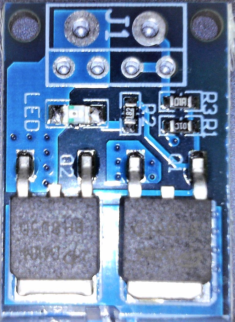
That FET has the option / room to add a heats sink

Pipes is showing where you scrape away the black epoxy and make contact with the PCB ground trace to heatsink the FET to the board. The LED connection is a bit blurry.

Dang TD must be getting late for you:zzz: there is a lot more than that going on....dang it looks like he's
added a Fet with some sort of Resistor Bridge, I assume this is all for the tact switch. Having said that on
post #3067 the 4th picture and the last are showing a + & - 12V point, it looks like these are where he
wired the glass led. It looks like and I read it somewhere that the original mosfets have been changed.

I sorta like the aluminum case he's using, I'd have to figure out how to slide out the battery tray.
A lot of good ideas in this thread but it looks to me that he's tried to shore up the module's
weakness.
 
PKOK,

TommyDee

Vaporitor
You can glue a heatsink on with thermal epoxy.

It was late but it is likely more that I haven't really dissected the PSM design.
I know he was showing how to incorporate a FET on the board. That isn't the switch-FET?

We should link that thread:
http://fuckcombustion.com/threads/v...op-and-in-car-use.23211/page-123#post-1413268

Okay, so this is a switch FET. The 10K resistor should be coming from the gate or the other end of the 330 ohm resistor. It powers an LED on the plus side when the gate is powered. The 330 ohm resistor is what latches the gate through the switch.

All 3 spots that the solder mask is removed from are ground. That means the one near the on-board LED is the tube LED and that wire is the ground side.

Power, negative, comes in on the FET's source pin. The output goes to the ground plane. Pipes is switching negative which is common. Positive is hardwired to the board. The trigger of the FET, the gate, has a 330 ohm resistor to the switch. And the other side of the switch goes to positive. There is a 10K resistor on the other end of the 330 ohm resistor that goes high when the switch is depressed. It is the junction of those two series resistors where the switch is wired. Yea, seams reasonable :cool:

@Pipes - feel free to correct my gleening.
 
Last edited:
TommyDee,

TommyDee

Vaporitor
I took a look at my FET switch with a closer eye. Indeed both FETs are switched together. The drive circuit above has one error - the end of the 10K resistor goes to ground. I suspect it is there to makes sure the gate doesn't float high in case the 330 ohm resistor looses a connection. The resistor values on mine are not quite the same. My switch has a 100 ohm resistor to drive the pair of gates. Still 10K to ground. 1.8K on the LED. It uses the dual D4184 mosfets.

49677627248_62001ccbcc_b.jpg
 
Last edited:

PKOK

Well-Known Member
You can glue a heatsink on with thermal epoxy.

I don't have that Mosfet or ANY on order, I still have a pocket full of the cheap ones from my first build & they seem to be working fine. Should I order it ? I'm sure I have a heatsink to fit.

Last night I ordered a Digital Voltmeter because I couldn't find my notes for the low voltage warning led.
https://www.ebay.com/itm/0-36-Digital-Voltmeter-Panel-DC-2-50-30V-Voltage-Mount-LED-Voltmeter-Red-dd/282668169676?ssPageName=STRK:MEBIDX:IT&_trksid=p2057872.m2749.l2649

Your saying Pipes wired an onboard Mosfet Switch? Does that negate the PWM issue you have with
the common Mosfet Trigger Switch?

I need to select & get a momentary switch on order. I do have a couple smaller ones leftover from vapeing box mods. I still haven't selected the enclosure either. Oh, and a battery tray, I could piece meal one but
that may make it difficult to remove.
 
PKOK,

TommyDee

Vaporitor
I like the battery tray from China with the leaf springs. Works a charm.

You don't need a heatsink just because we are pulling under 10 amps. And yes, Pipes is building a single FET version of the same circuit. So if you want to duplicate what he did, just use my image as a reference of how to hook things up. And no, there is no PWM signal so I don't worry about it in this circuit. Pipes has made it 'tried and tested'.

There is no reason you cannot use that angel-eye switch for driving the FET. Overkill maybe, but you get to pick your user interface.

For my runt I had an idea to put the FET circuit in with a quality tactile switch attached to it. Seems I have a perfect spot for it.

Call to arms; Does anyone know the frequency range that this circuit operates in?
 
TommyDee,

PKOK

Well-Known Member
duplicate what he did, just use my image as a reference of how to hook things up

What image is that?
I've not noticed any issues with PWM, but I agree his circuit is tried and true.

I never thought to look on utube for that. Nice work.
 
Last edited:
PKOK,

TommyDee

Vaporitor
This image - follow the traces and you see it is the same as Pipes did with minor variation in values.

49677627248_62001ccbcc_b.jpg


When I say PWM, I mean to send a PWM signal to the IH. Due to the fast switch rate of a PWM signal, if could set up a harmonic with the IH and blow it out.

Seems a choke would function beautifully to dampen the response in this instance.

Have you ever done radio control stuff?
 
Last edited:
TommyDee,

PKOK

Well-Known Member
Have you ever done radio control stuff?
No I haven't but did some control line stuff.

Sorry Buddy I'm not there yet, I'm sure I could figure it out with a few cups of coffee and a massive headache but I think I'll stick with the board. I'm slightly better with a schematic, much better with a pictograph.

I did discover something interesting, the BMS and the balancing Board can be wired together to the batts.
I noticed it on ebay the same bal board wired to the same "protection board" So enternal battery pack may be back on the table. Check it out, scroll to the bottom there's a larger picture.
https://www.ebay.com/itm/3S-12-6V-L...646006?hash=item2cbc3c8d76:g:~NAAAOSwuxFYvXrq

trying to figure out if I can get it all into this box
https://www.amazon.com/LeMotech-Pla...ctronics+7+x+5+x+3&qid=1584805619&sr=8-6&th=1
 
Last edited:
PKOK,

TommyDee

Vaporitor
Sweet, we have all the parameters now with a parts plan. I don't blame you on using the FET switch instead of doing what Pipes does. That is tedious work that is prone to failures until you get good at it. I never got good at it.

Next step is to draw the wiring diagram and assign wire gauges.

Careful about that eBay find. That is not a BMS on the cells... take a close look - that is a simple distribution board. We can disable the charge circuits on your 20A BMS however.

s-l1600.jpg


---

I wish I had a few more of these IH boards on hand. I really want to try driving one with an Arduino. Worst case it will need a filter network - best case is likely adding a proper choke setup. This is in relation to variable voltage to the IH. I cannot see another compact solution to managing voltage without going through some monstrous electronics or resistors. This doesn't affect your project but it is something I want to achieve. Implications could be far reaching.
 
Last edited:
TommyDee,

PKOK

Well-Known Member
Are you sure TD? I've seen the same in a few places. The BMS will charge until one battery reaches 4.2v and stops. Is it possible that this board just balances them out as the name implies ? If you search the number on the picture HX-3S-A10 It's the BMS. Possible?
 
PKOK,

TommyDee

Vaporitor
Okay, you got me on that but it still doesn't pass my smell test. Paralleling 2 charge circuits just goes against the grain.

Very important; if this is a valid circuit, it is only valid without the 12.6V charger being plugged in. Then the BMS charge circuit is bypassed.
 
TommyDee,
Top Bottom