
You are using an out of date browser. It may not display this or other websites correctly.
You should upgrade or use an alternative browser.
You should upgrade or use an alternative browser.
Fluxer Heaters, induction heaters for Dynavap
- Thread starter mr_cfromcali
- Start date
-
- Tags
- induction heater
But are the new robust FETs with the internal diodes suitable for this purpose or overkill?
Actually ,they are the best option for the job .
More importantly, is the package the same for an easy swap?
That's the main problem !

Actually ,they are the best option for the job .
That's the main problem !
Sorry, I was offline for a bit, and it seems like @stardustsailor has dropped more knowledge while I was away. And now I need to run into a meeting.
Tell me more - I'll reply when I have time!
Last edited:
Introduction
Resonant converters are one of the most exciting power supply topologies. These converters are popular for many applications because the performance increases power efficiency, minimizes components count, and reduces Electromagnetic Interference (EMI) over older power supply topologies. Soft switching is the representative feature of resonant converters.[1][2] However, use of the body diode in resonant converters sometimes leads to system failures. The stored charge in the body diode should be completely removed to avoid high current and voltage spikes, including high dv/dt and di/dt, in these topologies. Therefore, critical parameters of power MOSFETs; such as Coss(er), Qrr, and reverse-recovery dv/dt; directly affect dynamic performance of resonant converters A new power MOSFET, called UniFET™ II, is optimized for resonant converters. It provides better reliability and higher efficiency in resonant converters.
Resonant Converters Reliability
Several topologies of DC-DC converters for server and telecom power supplies have been introduced to reduce switching losses, device stresses on the power MOSFETs, and Radio Frequency Interference (RFI) while achieving high power density. Resonant converters that utilize the body diode of MOSFETs for Zero-Voltage Switching (ZVS) are very suitable for these applications. Specifically, the phase-shifted ZVS full-bridge converters have been widely accepted for high-end power supplies since they allow all switches to operate at ZVS by effective COSS of power MOSFETs and leakage inductance of transformer without an additional auxiliary switch. However, ZVS range is very narrow and the freewheeling current consumes high circulating energy. In the late 1990s, power MOSFET failures were reported in the phase-shifted ZVS full-bridge topology. One cause of failure is slow reverse recovery of the body diode by low reverse voltage. The other failure is due to the Cdv/dt shoot-through at no-load or light-load conditions.[3][4]
https://www.fairchildsemi.com/application-notes/AN/AN-9725.pdf
Soft switching (resonant)
What is soft (resonant) switching? ›
Soft switching begins one electrical parameter to zero (current or voltage) before the switch is turned on or off. This has benefits in terms of losses.
› The smooth resonant switching waveforms also minimize EMI.
› Common topologies like phase- shifted ZVS and LLC are soft switched only at turn-on.
What is the difference between zero voltage switching (ZVS) and zero current switching (ZCS)? ›
As both names imply either voltage or current within the transistor is zero before switching occurs.
– For ZVS, the transistor will be turned in at zero VDS voltage to reduce the turn on switching loss.
– For ZCS, the transistor will be turned off at zero ID current to reduce the turn off switching loss.
Why is there a need for a rugged or fast body diode?
› Most resonant circuits are half- or full-bridge topologies (2 or 4 transistors).
As transistors are switched on and off, energy can be left in the transistor and this can cause failure. Due to switching times if this only happens occasionally a rugged body diode is sufficient (CoolMOS™ P7).
If due to fast transition times it happens continually then a fast body diode is required to make sure all the energy will leave the transistor (CoolMOS™ CFD7 series).
https://www.infineon.com/dgdl/Infin...N.pdf?fileId=db3a3043338c8ac80133aca62ba63047
https://www.infineon.com/dgdl/Infin...N.pdf?fileId=5546d46147a9c2e40147d3430e927e5d
https://www.fairchildsemi.com/application-notes/AN/AN-7536.pdf
https://www.st.com/content/ccc/resource/sales_and_marketing/promotional_material/magazine/7a/dd/a6/78/0f/a7/49/5d/TP 1033 Why use a fast diode MOSFET in a LLC.pdf/files/TP 1033 Why use a fast diode MOSFET in a LLC.pdf/jcr:content/translations/en.TP 1033 Why use a fast diode MOSFET in a LLC.pdf
https://www.electronicdesign.com/po...sfet-tailored-zero-voltage-switching-supplies
And an alternative to FETs :
https://gansystems.com/wp-content/uploads/2018/02/GN001_Design_with_GaN_EHEMT_180228-1.pdf
Still @Hackerman has a point .
The actual type of the OEM FET ,used at the "5-12 Volt ZVS IH module "
is not the best option .The 30N06G
http://www.unisonic.com.tw/datasheet/30N06.pdf
Rds = 40 mΩ is quite high Drain-to-Source On resistance .
Last edited:
Introduction
Resonant converters are one of the most exciting power supply topologies. These converters are popular for many applications because the performance increases power efficiency, minimizes components count, and reduces Electromagnetic Interference (EMI) over older power supply topologies. Soft switching is the representative feature of resonant converters.[1][2] However, use of the body diode in resonant converters sometimes leads to system failures. The stored charge in the body diode should be completely removed to avoid high current and voltage spikes, including high dv/dt and di/dt, in these topologies. Therefore, critical parameters of power MOSFETs; such as Coss(er), Qrr, and reverse-recovery dv/dt; directly affect dynamic performance of resonant converters A new power MOSFET, called UniFET™ II, is optimized for resonant converters. It provides better reliability and higher efficiency in resonant converters.
Resonant Converters Reliability
Several topologies of DC-DC converters for server and telecom power supplies have been introduced to reduce switching losses, device stresses on the power MOSFETs, and Radio Frequency Interference (RFI) while achieving high power density. Resonant converters that utilize the body diode of MOSFETs for Zero-Voltage Switching (ZVS) are very suitable for these applications. Specifically, the phase-shifted ZVS full-bridge converters have been widely accepted for high-end power supplies since they allow all switches to operate at ZVS by effective COSS of power MOSFETs and leakage inductance of transformer without an additional auxiliary switch. However, ZVS range is very narrow and the freewheeling current consumes high circulating energy. In the late 1990s, power MOSFET failures were reported in the phase-shifted ZVS full-bridge topology. One cause of failure is slow reverse recovery of the body diode by low reverse voltage. The other failure is due to the Cdv/dt shoot-through at no-load or light-load conditions.[3][4]
https://www.fairchildsemi.com/application-notes/AN/AN-9725.pdf
Soft switching (resonant)
What is soft (resonant) switching? ›
Soft switching begins one electrical parameter to zero (current or voltage) before the switch is turned on or off. This has benefits in terms of losses.
› The smooth resonant switching waveforms also minimize EMI.
› Common topologies like phase- shifted ZVS and LLC are soft switched only at turn-on.
What is the difference between zero voltage switching (ZVS) and zero current switching (ZCS)? ›
As both names imply either voltage or current within the transistor is zero before switching occurs.
– For ZVS, the transistor will be turned in at zero VDS voltage to reduce the turn on switching loss.
– For ZCS, the transistor will be turned off at zero ID current to reduce the turn off switching loss.
Why is there a need for a rugged or fast body diode?
› Most resonant circuits are half- or full-bridge topologies (2 or 4 transistors).
As transistors are switched on and off, energy can be left in the transistor and this can cause failure. Due to switching times if this only happens occasionally a rugged body diode is sufficient (CoolMOS™ P7).
If due to fast transition times it happens continually then a fast body diode is required to make sure all the energy will leave the transistor (CoolMOS™ CFD7 series).
https://www.infineon.com/dgdl/Infin...N.pdf?fileId=db3a3043338c8ac80133aca62ba63047
https://www.infineon.com/dgdl/Infin...N.pdf?fileId=5546d46147a9c2e40147d3430e927e5d
https://www.fairchildsemi.com/application-notes/AN/AN-7536.pdf
https://www.st.com/content/ccc/resource/sales_and_marketing/promotional_material/magazine/7a/dd/a6/78/0f/a7/49/5d/TP 1033 Why use a fast diode MOSFET in a LLC.pdf/files/TP 1033 Why use a fast diode MOSFET in a LLC.pdf/jcr:content/translations/en.TP 1033 Why use a fast diode MOSFET in a LLC.pdf
https://www.electronicdesign.com/po...sfet-tailored-zero-voltage-switching-supplies
And an alternative to FETs :
https://gansystems.com/wp-content/uploads/2018/02/GN001_Design_with_GaN_EHEMT_180228-1.pdf
Still @Hackerman has a point .
The actual type of the OEM FET ,used at the "5-12 Volt ZVS IH module "
is not the best option .The 30N06G
http://www.unisonic.com.tw/datasheet/30N06.pdf
Rds = 40 mΩ is quite high Drain-to-Source On resistance .
Thanks again for sharing all of this information, @stardustsailor !
Two quick, preliminary questions:
1: I've read several of the articles to which you linked, and went looking to buy some IRFBL17N50Ls to play around with. Unfortunately, I can't find them anywhere. The article you linked to is dated from 2000, and I can't tell if this particular MOSFET ever made it to market. Any ideas? Any suggestions for a soft-switching FET in a DPAK or DPAK2 package?
2. For my circuits, I'm using the LR7843 instead of the 30N06. I believe they are generally similar, but I'm curious about your take on that, and if there is a alternate DPAK-sized FET you prefer?
LR7843 datasheet: https://www.alldatasheet.com/view.jsp?Searchword=LR7843
30N06 datasheet: https://www.alldatasheet.com/view.jsp?Searchword=30N06
Thanks again! I welcome the opportunity to make these devices better!
The IRFB17N50L comes only at TO220 package .
http://www.digipart.com/part/irfb17...nEAWGH_PFNjMhelzaeFh1Ke5X6wuOcABoCUegQAvD_BwE
The LR7843 is a very good MOSFET for a ZVS power supply .
A bit better than the NTD4806N ( also a better alternative than the oem 30N06 )
https://www.onsemi.com/pub/Collateral/NTD4806N-D.PDF
Here are few MOSFETs that I consider ideal for the job :
https://gr.mouser.com/datasheet/2/308/NVD5890NL-D-1381937.pdf
https://gr.mouser.com/datasheet/2/308/NTD5C446N-D-1381619.pdf
https://gr.mouser.com/datasheet/2/389/std134n4f7ag-1156498.pdf
https://gr.mouser.com/datasheet/2/389/std170n4f7ag-1156502.pdf

Last edited:
The IRFB17N50L comes only at TO220 package .
http://www.digipart.com/part/irfb17...nEAWGH_PFNjMhelzaeFh1Ke5X6wuOcABoCUegQAvD_BwE
The LR7843 is a very good MOSFET for a ZVS power supply .
A bit better than the NTD4806N ( also a better alternative than the oem 30N06 )
https://www.onsemi.com/pub/Collateral/NTD4806N-D.PDF
Here are few MOSFETs that I consider ideal for the job :
https://gr.mouser.com/datasheet/2/308/NVD5890NL-D-1381937.pdf
https://gr.mouser.com/datasheet/2/308/NTD5C446N-D-1381619.pdf
https://gr.mouser.com/datasheet/2/389/std134n4f7ag-1156498.pdf
https://gr.mouser.com/datasheet/2/389/std170n4f7ag-1156502.pdf
Cool! Glad the LR7843 is a good one in your consideration.
I'm very eager to check out the alternative FETs you listed! Thank you for the suggestions! I'm in the US, and a quick check shows I can get the NVD5890NL and NTD5C446NT4G from Mouser and probably others, so I'll give those a try straight away. The STD170N4F7AG has some availability issues in the US (seems to only be available in bulk quantities here, whereas single chip quantities are available in Europe. They could ship single units here, of course, but the shipping cost makes that less attractive.) According to the ST site, their STD34N4F7AG is not currently in production.
Of the NVD5890NL and NTD5C446NT4G, do you prefer one over the other? To my unschooled eye, the NVD5890NL looks to be the slightly more robust of the two on paper, but they seem very similar overall, and I assume the slightly greater power handling comes with some associated cost I'm not seeing. And I'll admit that I could be completely wrong about both that statement and my reading of the data sheets.

Their prices appear to be within 10% of each other and consistent with the LR7843, and they're all the same package, so if the other aspects of the circuit remain unchanged, it would be an exceptionally easy parts switch to make. It isn't my intention to ask you to design my circuit for me, by the way, but at the same time, I respect your obvious knowledge on this subject, and I like using the best part for the job at hand, even if it costs a bit more.
WRT to the IRFB17N50L - As long as I am ordering parts, I think I'll get a few of the T0-220 versions of this to play around with. Not every portable heater need to fit in a pocket.
")
Thanks again, @stardustsailor , for your contributions to this thread and the topic!!
Last edited:
The ideal MOSFET !
1 ) VDS >= 40 V
2 ) ID cont. >= 40 Α
3 ) RDS(on) =< 10mΩ
4 ) QGS =< 25 nC
5 ) Trr =< 50 nS
6 ) Qrr =< 50 nC
1 ) VDS >= 40 V
2 ) ID cont. >= 40 Α
3 ) RDS(on) =< 10mΩ
4 ) QGS =< 25 nC
5 ) Trr =< 50 nS
6 ) Qrr =< 50 nC
Edit / PS :
@mr_cfromcali you maybe already aware of that the "5-12V ZVS IH module"
is not really meant to be a real IH device ,but mostly an educational device.
The higher wattage IH devices have their working coils water -cooled .
Thing is that for our purpose -luckily enough- the IH device only operates for brief time periods
(10 sec at most ) ,heating a small mass (not a rod ,but rather a tube ).
Thus we can "get away" from possible hazard -having a air cooled working coil- even
with "educational" devices like the 5-12 VDC ZVS IH module .
Or any other low wattage IH circuit with a non water -cooled work coil.
But if shit can happen ,eventually will happen ,at least most of the times .
Therefore a work coil overheat protection is not just a nice idea ,
but rather a "must " ,especially when Li-ion or LiPO battery cells are present close by.
Actually it's a very cheap and easy add-on .
All it is needed is this :
https://www.ebay.com/itm/KSD9700-Bi...var=431975311065&_trksid=p2057872.m2749.l2649
A Normally Closed ( NC ) KSD-9700 Bimetallic Disc Thermostat ( circuit breaker ).
https://www.nikom.biz/pdf/KSD-9700.pdf
I've already tried the 85°C one and it never tripped under heavy usage of the IH device,
at summer .
I'm going to try the 80°C and ( of the more "strict thermal protection policy ") 75°C .
While they are rated for ≥ 10000 times tripping @ 250 V / 5 A ,
connecting them to the MOSFET switch "Trigger " circuitry ( 12 V / 0.12 A )
their service life is drastically extended .
Furthermore ,under normal usage the breaker will trip very few times, if any at all .
BUt one can never be sure .
Curious pets ,small kids and unexperienced or disabled or even stupid adults ,
are few examples of " Uh-Oh ! " .
Once the work coli's temperature increases a bit above the selected threshold temperature,
the breaker trips and the power supply to the "trigger" circuit is interrupted .
The IH device can not be activated until the work coil temperature drops a bit below the
breakers reset temperature .
This small sub-circuit may never be activated.
But if the circumastances are such and it doesactivated ,
it may save the user of the IH from quite some trouble .
From the smallest one (i.e. a shorted work coil ,with it's insulation varnish totally baked and a damaged IH device )
to the biggest ones
(i.e. setting your sofa on fire or having the Li-ion/LiPO cells " fire-cracking "
on top of the table ) .
Better safe ,than sorry .
Especially at these cases.
More :
http://fuckcombustion.com/threads/vapcap-diy-induction-heating-bits-n-pieces.33216/#post-1294337
Last edited:
The ideal MOSFET !
1 ) VDS >= 40 V
2 ) ID cont. >= 40 Α
3 ) RDS(on) =< 10mΩ
4 ) QGS =< 25 nC
5 ) Trr =< 50 nS
6 ) Qrr =< 50 nC
Thanks! Looking at the data for these four MOSFETs:
Ideal MOSFET Spec NTD5C446N NVD5890NL IRLR7843 30N06
1 ) VDS >= 40 V 40V 40V 30V 55V
2 ) ID cont. >= 40 Α 110A 123A 161A 30A
3 ) RDS(on) =< 10mΩ 3.5mΩ 3.7mΩ 3.3mΩ 13.3mΩ
4 ) QGS =< 25 nC 12.2 13.7 9.1 6
5 ) Trr =< 50 nS 46 35 39 33
6 ) Qrr =< 50 nC 40 34 36 71
The NVD5890NL struck me as the best, but the LR7843 seems to hold its own pretty well within this spec set, so I'm happy at that as well. (Forgive the poor formatting.)
Time to order up some more MOSFETS.

Edit / PS :[/B]
@mr_cfromcali you maybe already aware of that the "5-12V ZVS IH module"
is not really meant to be a real IH device ,but mostly an educational device.
The higher wattage IH devices have their working coils water -cooled .
Thing is that for our purpose -luckily enough- the IH device only operates for brief time periods
(10 sec at most ) ,heating a small mass (not a rod ,but rather a tube ).
Thus we can "get away" from possible hazard -having a air cooled working coil- even
with "educational" devices like the 5-12 VDC ZVS IH module .
Or any other low wattage IH circuit with a non water -cooled work coil.
Yep.

But if shit can happen ,eventually will happen ,at least most of the times .
Therefore a work coil overheat protection is not just a nice idea ,
but rather a "must " ,especially when Li-ion or LiPO battery cells are present close by.
Actually it's a very cheap and easy add-on .
All it is needed is this :
https://www.ebay.com/itm/KSD9700-Bimetal-Disc-Thermostat-Thermal-Protector-250V-5A-40-135-centigrade/132643015215?ssPageName=STRK:MEBIDX:IT&var=431975311065&_trksid=p2057872.m2749.l2649
A Normally Closed ( NC ) KSD-9700 Bimetallic Disc Thermostat ( circuit breaker ).
https://www.nikom.biz/pdf/KSD-9700.pdf
I've already tried the 85°C one and it never tripped under heavy usage of the IH device,
at summer .
I'm going to try the 80°C and ( of the more "strict thermal protection policy ") 75°C .
While they are rated for ≥ 10000 times tripping @ 250 V / 5 A ,
connecting them to the MOSFET switch "Trigger " circuitry ( 12 V / 0.12 A )
their service life is drastically extended .
Furthermore ,under normal usage the breaker will trip very few times, if any at all .
BUt one can never be sure .
Curious pets ,small kids and unexperienced or disabled or even stupid adults ,
are few examples of " Uh-Oh ! " .
Once the work coli's temperature increases a bit above the selected threshold temperature,
the breaker trips and the power supply to the "trigger" circuit is interrupted .
The IH device can not be activated until the work coil temperature drops a bit below the
breakers reset temperature .
This small sub-circuit may never be activated.
But if the circumastances are such and it doesactivated ,
it may save the user of the IH from quite some trouble .
From the smallest one (i.e. a shorted work coil ,with it's insulation varnish totally baked and a damaged IH device )
to the biggest ones
(i.e. setting your sofa on fire or having the Li-ion/LiPO cells " fire-cracking "
on top of the table ) .
Better safe ,than sorry .
Especially at these cases.
More :
http://fuckcombustion.com/threads/vapcap-diy-induction-heating-bits-n-pieces.33216/#post-1294337
Wow!
 Thanks, @stardustsailor! Your build is the safest portable induction heater I've seen.
I agree that these devices and their batteries have the potential to be very dangerous, even if used and handled with care. No argument. People are quite cavalier about them, but shit can indeed go badly with them, sometimes very randomly.
I'll see what I can do to apply your safety circuit (or at least its concept) to my own devices - and I truly do appreciate you sharing these safety features, that's a very generous gift to the DV community!!! - but a fair warning to all: I doubt I'll be able to adopt these features immediately. The first generation of versions of the devices I'm currently developing will likely be released with at least some of these vulnerabilities still unchecked. This is consistent with the other portable vapcap IH devices on the market at the moment - not much comfort, I know, but true.
Treat all of these devices with caution, including battery chargers and battery storage locations.
Yes .The NVD5890NL seems to be one of the best possible choices .
Still ,the LR7843 is still well within the ideal specs ,with it's VDS being the only exception .
But if the IH supply voltage is lower than 12 VDC ( say 10 VDC ),
then it is also a quite robust FET ,ideal fot the task .
Still ,the LR7843 is still well within the ideal specs ,with it's VDS being the only exception .
But if the IH supply voltage is lower than 12 VDC ( say 10 VDC ),
then it is also a quite robust FET ,ideal fot the task .
Hope everyone had a good weekend. A few updates for the curious:
Flux Deluxe (3x 18650 IH): I'll be honest, it's been challenging to package the heater and supporting components in a way that safely fit and function inside the 1590B enclosure. I like these sorts of challenges, though, and after some back and forth with the design I finally came up with a solution I like. My latest revision of this circuit finally brings the PWM relay onto the circuit board itself, which eliminates some wires and should make for a much more compact circuit, which this device needs. It will also make the device easier to assemble, which will help us all.
This circuit is done, and some copies of it are on their way to me right now and will hopefully be here by the end of the week. I'll post some updates once I have the boards and can put them through their paces. My fingers are crossed - these could be very close to done if they work as expected.
Mother Fluxer (3x 26650 IH):
Mother Fluxer PCB: I learned a few things while redesigning the Deluxe that I'll be applying to the Mother Fluxer. The two devices have a lot in common and the techniques that saved space on the Deluxe will also save space on the Mother Fluxer. I have a few stray components, like the charge port and maybe the on/off switch, that I'll move onto the Mother Fluxer's circuit board. This will make the devices simpler to build, and I also believe that fewer wires = fewer points of failure.
Mother Fluxer Case: Height issues solved! I found a new case for the Mother Fluxer, the Hammond 1590BBS. Same footprint as the 1590BB, but about 8mm taller:
1590BB internal height: 29.75mm; 1.171"
1590BBS internal height: 37.85mm; 1.490"
The batteries and heater fit inside perfectly, and the lid closes properly and covers everything, with sufficient space under the battery tray for the battery management circuit and airflow, so I'm confident this is the right enclosure for this device. I have some on the way, and will be ready to start turning the crank on these just as soon as I migrate the improvements from the Deluxe circuit board to the Mother Fluxer's.
Tactile Switch input filter: @stardustsailor generously shared some very exciting technologies with me/us/this thread last week, small circuits that will make these IH devices safer and more reliable. I have been trying to absorb all that he shared. One of the circuits he shared was a small VHF filter that "debounces" the signal from the tactile switch, which he explains above and on his site (link above). I was able to generate a small circuit board from his files, and have a few copies of it on their way to me - they should be here in a week or so, shortly after the latest Deluxe PCB arrives. I also ordered the components to build out the few copies that are coming. I'll definitely report back on this after the parts arrive.
Summary
Both of the new Fluxer Heater portables are progressing and each is getting closer to being ready for sale - I am very hopeful I'll have them ready to go this month. I'll know a lot more about the future of both devices after I receive the latest Deluxe circuit boards later this week or early next week.
Thanks for your interest and support! More to come.")
Flux Deluxe (3x 18650 IH): I'll be honest, it's been challenging to package the heater and supporting components in a way that safely fit and function inside the 1590B enclosure. I like these sorts of challenges, though, and after some back and forth with the design I finally came up with a solution I like. My latest revision of this circuit finally brings the PWM relay onto the circuit board itself, which eliminates some wires and should make for a much more compact circuit, which this device needs. It will also make the device easier to assemble, which will help us all.
This circuit is done, and some copies of it are on their way to me right now and will hopefully be here by the end of the week. I'll post some updates once I have the boards and can put them through their paces. My fingers are crossed - these could be very close to done if they work as expected.
Mother Fluxer (3x 26650 IH):
Mother Fluxer PCB: I learned a few things while redesigning the Deluxe that I'll be applying to the Mother Fluxer. The two devices have a lot in common and the techniques that saved space on the Deluxe will also save space on the Mother Fluxer. I have a few stray components, like the charge port and maybe the on/off switch, that I'll move onto the Mother Fluxer's circuit board. This will make the devices simpler to build, and I also believe that fewer wires = fewer points of failure.
Mother Fluxer Case: Height issues solved! I found a new case for the Mother Fluxer, the Hammond 1590BBS. Same footprint as the 1590BB, but about 8mm taller:
1590BB internal height: 29.75mm; 1.171"
1590BBS internal height: 37.85mm; 1.490"
The batteries and heater fit inside perfectly, and the lid closes properly and covers everything, with sufficient space under the battery tray for the battery management circuit and airflow, so I'm confident this is the right enclosure for this device. I have some on the way, and will be ready to start turning the crank on these just as soon as I migrate the improvements from the Deluxe circuit board to the Mother Fluxer's.
Tactile Switch input filter: @stardustsailor generously shared some very exciting technologies with me/us/this thread last week, small circuits that will make these IH devices safer and more reliable. I have been trying to absorb all that he shared. One of the circuits he shared was a small VHF filter that "debounces" the signal from the tactile switch, which he explains above and on his site (link above). I was able to generate a small circuit board from his files, and have a few copies of it on their way to me - they should be here in a week or so, shortly after the latest Deluxe PCB arrives. I also ordered the components to build out the few copies that are coming. I'll definitely report back on this after the parts arrive.
Summary
Both of the new Fluxer Heater portables are progressing and each is getting closer to being ready for sale - I am very hopeful I'll have them ready to go this month. I'll know a lot more about the future of both devices after I receive the latest Deluxe circuit boards later this week or early next week.
Thanks for your interest and support! More to come.
Last edited:
It was a late night last night, lol. Back with a few updates.
Turns out I couldn't wait to put a prototype together, as I was just too eager to see how it would work. This is the result. Please keep in mind that I started this effort at 2am and knocked off at 4am. There's still some work to be done - that charging cable is probably just temporary, for example, and I still have some switches to place, too. That said:
It works!
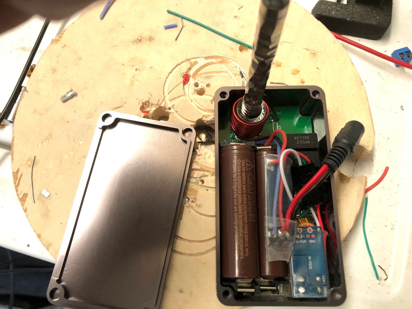
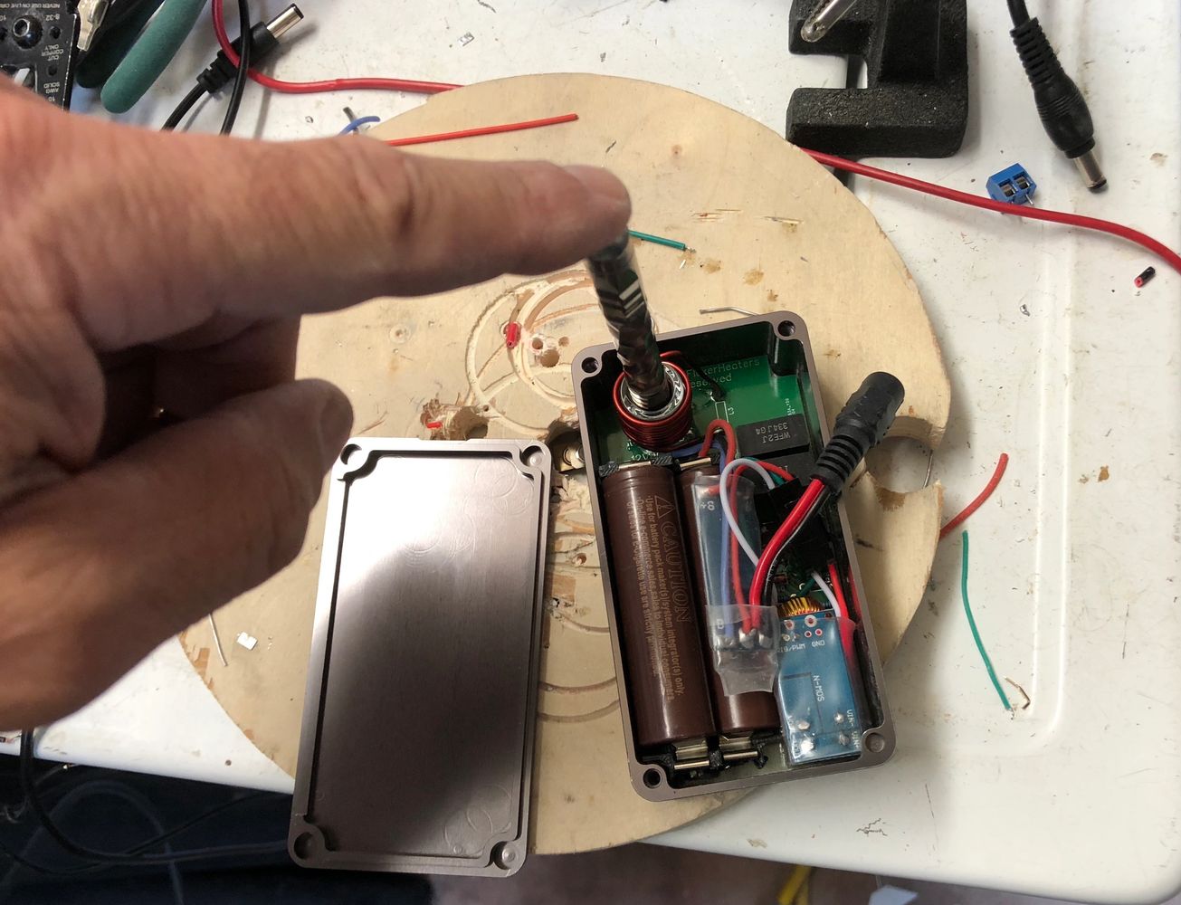
IMPORTANT: The batteries in the following clip are NOT fresh - in fact, they are the same batteries I used all evening, and by the time I shot this they were almost done. It was late, and battery life wasn't first on my mind. So...I'll post some better clips with shorter heating times soon.
Thanks for the support! I'll do some more work on it tonight and try to finish it up.
More to come

Wow, just been directed here by a link in the DV thread. This little IH is the coolest and most desirable I've yet seen. Could actually see myself taking this places. Nice job man.
Wow, just been directed here by a link in the DV thread. This little IH is the coolest and most desirable I've yet seen. Could actually see myself taking this places. Nice job man.
Thanks! If you have a few minutes, there are some updates throughout this thread. The most significant is that the 2x 18650 model in your quote is actually going to be a 3x 18650 in the same size case: The Flux Deluxe. I am waiting on some circuit boards to arrive - it's pretty close.
I also have a 3x 26650 heater I've been working on, the Mother Fluxer. It's also pictured in this thread, and its development is actually a couple of weeks ahead of the Deluxe.
Stay tuned - I should have some actual product for sale by the end of the month
stark1
Lonesome Planet
Regarding your portable, curious why you decided to have the induction coil facing 90
Degrees from the length of the casing.
It would be more convenient to insert the length of the VapCap into the long axis of
The casing, rather than perpendicular to it.
Especially if you are wearing it on your belt. YMMV.
Degrees from the length of the casing.
It would be more convenient to insert the length of the VapCap into the long axis of
The casing, rather than perpendicular to it.
Especially if you are wearing it on your belt. YMMV.
Regarding your portable, curious why you decided to have the induction coil facing 90
Degrees from the length of the casing.
It would be more convenient to insert the length of the VapCap into the long axis of
The casing, rather than perpendicular to it.
Especially if you are wearing it on your belt. YMMV.
Hi,
Thanks for the reply. The short answer is that this orientation is a LOT easier to develop, especially for an initial release.
Also, tbh, “belt wearable” was not a use case I considered.

Sorry.
pxl_jockey
Just a dude
@mr_cfromcali Can you please explain how the Mother Fluxer and Flux Deluxe differ? As a potential customer, I want to know how you see the respective strengths and compromises of each product.
Since they are both portable, it’s a matter of deciding which fits my use case best. Does it basically boil down to the FD will be way more pocketable, thus more portable for slightly more money; whereas the MF will have more power in a slightly bigger form factor for $25 or so cheaper? Can I get weight differences please? If carrying it in my man-bag, less weight could be a factor for sure. I’m thinking either could easily accommodate a day out worth of usage, is that reasonable?
Many people have had success using the S&B Mighty’s charger with their 18650 IHs, is this a good match for the Fluxer Deluxe in your opinion? Sorry for all the questions! And thanking you kindly in advance!
@mr_cfromcali Can you please explain how the Mother Fluxer and Flux Deluxe differ? As a potential customer, I want to know how you see the respective strengths and compromises of each product.
Since they are both portable, it’s a matter of deciding which fits my use case best. Does it basically boil down to the FD will be way more pocketable, thus more portable for slightly more money; whereas the MF will have more power in a slightly bigger form factor for $25 or so cheaper? Can I get weight differences please? If carrying it in my man-bag, less weight could be a factor for sure. I’m thinking either could easily accommodate a day out worth of usage, is that reasonable?
Many people have had success using the S&B Mighty’s charger with their 18650 IHs, is this a good match for the Fluxer Deluxe in your opinion? Sorry for all the questions! And thanking you kindly in advance!
Hi,
Thanks for the great questions, @pxl_jockey ! I'll answer as many as I can at the moment.
> Can you please explain how the Mother Fluxer and Flux Deluxe differ? What are their respective use cases? (paraphrasing)
That's a very reasonable question. I see these devices this way: The Deluxe's distinctive feature is its small size. It will bring 3x 18650 power (12V @ 3000 maH) to a device that is the same size as a PSM, which runs on a 12V @ 900 mAh battery. Same size device, ~3x the capacity. Plus it will have easily accessible and replaceable batteries. This is not meant to be a knock in on the PSM in any way - it's a breakthrough device. But this does improve upon it.
[The above paragraph has been corrected. My original mAh math was wrong. Thank you, @phattpiggie , for the clarification!
]The Deluxe will be housed in these CNC'd aluminum enclosures:

These have smooth edges and rounded corners, and should be "pocket friendly." Or at least, not pocket UN-friendly.
The final price is still TBD, depending on the way the final components shake out. @stardustsailor contributed some extremely useful circuits late in my development cycle, and they're so compelling that I want to include them if I can. I'll know more in another week or two, once I have all of the parts in house.
In contrast, the Mother Fluxer's distinctive feature is its capacity. The 26650 battery can store approx. 5,000 mAh of power, at up to 30A of peak power. It has substantial storage capacity.
[The above paragraph has been corrected. My original mAh math was wrong. Thank you, @phattpiggie , for the clarification!
]This is still a relatively small device, but it isn't pocket sized unless you sport some old school cargo shorts:
Technical drawing of the 1590BBS with dimensions (PDF)
120mm x 94mm x 42mm (4.7" x 3.7" x 1.7")
Because this device is a bit bigger than the Deluxe, it was easier to design and should be a little easier to build. The main reason for the price difference between the MF and the Deluxe, though, is that they use different enclosures. The CNC'd aluminum enclosure the Deluxe needs is somewhat pricey and costs about twice as much as the MF's enclosures. I really like the Deluxe's enclosure, however, especially since they have straight sides (Hammond enclosures usually have angled sides) and are just a bit bigger than the regular 1590B enclosure - the extra couple of mm is absolutely necessary for this build to work.
The MF will also have some options that aren't possible for the Deluxe - some different corner treatments (thumbscrews, magnets, etc.), and likely some LED lighting, too. I also think it will be possible for me to offer a very basic and (relatively) inexpensive version of the MF - a basic case with basic features, maximum capacity, and a relatively cheap price. That's my hope, anyway.
In summary: my two portable devices will have a lot of features in common, but will split on physical size and capacity. Choose the one that makes the most sense for your situation.
>Can I get weight differences please? If carrying it in my man-bag, less weight could be a factor for sure. I’m thinking either could easily accommodate a day out worth of usage, is that reasonable?
I'll publish their respective weights, with batteries, after I build out the next batch of circuit boards, as those should be complete or very close to it. Weight info will be available before I sell any of these.
> Many people have had success using the S&B Mighty’s charger with their 18650 IHs, is this a good match for the Fluxer Deluxe in your opinion? Sorry for all the questions! And thanking you kindly in advance!
I own a Crafty (it charges via USB) and am not familiar with the Might's PSU, but if you want to post the specs I'll take a look. It should work fine as long as it is >=12V/6A and uses a standard sized, center positive tip.
Thanks for your questions! Feel free to ask followups as necessary. More to come.
Last edited:
Fat Freddy
FUCK CANCER TOO !
@mr_cfromcali ... Just by way of clarification, which side of the enclosure will the coil insertion hole be situated?
TIA!
.
TIA!
.
@mr_cfromcali ... Just by way of clarification, which side of the enclosure will the coil insertion hole be situated?
TIA!
.
Hi @Fat Freddy . For both devices, the boxes will be oriented so the lids face UP, and the Dynavap is inserted in via a hole in the lid.
I'm waiting for the next circuit boards before I build out any more devices, as they will be the final designs or very close to them. I'll definitely post pictures once I have them.
@mr_cfromcali you may want to amend your figures.
3 18650's or 26650's in series gives you 12.6v but your mah figures are wrong.
In a parallel configuration the mah's would be the figures you quote.
'mAh stay the same when you connect cells in series - provided that cells are all of the same mAh capacity. Special and unusual case If two cells are connected in series and they have differing mAh capacities the effective capacity is that of the lower mAh capacity cells.'
https://electronics.stackexchange.com/questions/20701/adding-mah-when-wiring-battery-cells-in-series
None of the IH's @Pipes builds are meant to be charged with the Mighty adapter it's rated at 3a which will more than likely damage the cells.
The recommended charger is rated at 1 amp.

Regarding your portable, curious why you decided to have the induction coil facing 90
Degrees from the length of the casing.
It would be more convenient to insert the length of the VapCap into the long axis of
The casing, rather than perpendicular to it.
Especially if you are wearing it on your belt. YMMV.
I get the belt thing, but for those of use who are still trying to be young and hip
 and don't wear utility belts . . I like the flat side down thing for when I'm at a pub garden table for example. It would be a visually more subtle process, and subtlety is my biggest draw to the IH. But as you said OMMV.
I get the belt thing, but for those of use who are still trying to be young and hip
OK, thanks for explaining that a bit more. I guess I never considered using/heating the DV that way, so it's good to become aware of another blind spot, lol. I'll mull it over. I think the batteries make a vertical, axial, belt-worn orientation challenging to pull off...but I won't rule it out completely. Thanks again.
pxl_jockey
Just a dude
I like your answers @mr_cfromcali and I’m happy that you are taking the time to acquire the bits that stardustsailor posted on. If you didn’t already know, he is one of FC’s technical geniuses and materials expert. That there are so many very smart people hanging on FC, happy to share or help, still amazes me. SDS is one of the most genuinely helpful people with an encyclopaedic knowledge that I’ve encountered.
Gotta say I’m super impressed with you A) understanding him & B) implementing the improvements so quickly. It speaks volumes about your desire to make the best and safest operating IH device that you can.
Some people wouldn’t be so willing to take constructive feedback on their “baby”, stubbornly insisting it’s “fine” as they’ve designed it. That you happily take the extra time & money to do it well? Well done.
Same as @mrb , I’m not trying to be a Batman with my trusty utility belt! Surely there’s a perfect pouch/carry for everyone out there who wants that? Put a belt-clip on this beauty and you’ve killed it.
You’ve brought up the belt IH w/separate batteries idea earlier in the thread, but I’m not sure exactly what you’re after @stark1 do you envision heating your vapcap whilst in full stride? You know I respect ya and I’m not trying to be a smart arse. Just trying to understand. Are most folks gonna want that?
Gotta say I’m super impressed with you A) understanding him & B) implementing the improvements so quickly. It speaks volumes about your desire to make the best and safest operating IH device that you can.
Some people wouldn’t be so willing to take constructive feedback on their “baby”, stubbornly insisting it’s “fine” as they’ve designed it. That you happily take the extra time & money to do it well?
Well done.Same as @mrb , I’m not trying to be a Batman with my trusty utility belt! Surely there’s a perfect pouch/carry for everyone out there who wants that? Put a belt-clip on this beauty and you’ve killed it.
You’ve brought up the belt IH w/separate batteries idea earlier in the thread, but I’m not sure exactly what you’re after @stark1 do you envision heating your vapcap whilst in full stride? You know I respect ya and I’m not trying to be a smart arse. Just trying to understand.
Are most folks gonna want that?