Halogen Vaporiser

smokeliss

New Member
Hi everyone,

New here, but thought you would all like to have a look at what I’m starting to put together.

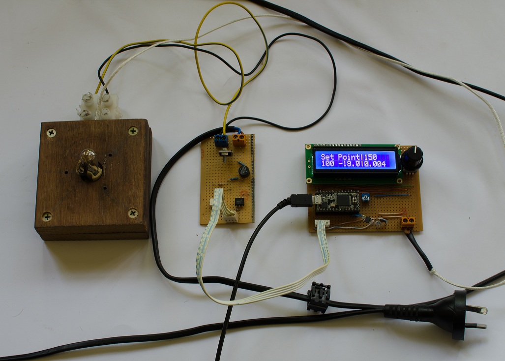
This is the current test bed.

Left to right:

Test stand, currently using a single 100W 240v halogen bulb. Planning on upping it to 3x 150W halogen tubes. Thermocoulpe is sitting next to the bulb here.

Middle: Heater driver, TRIAC controlled, took heat sink off temporary, may be needed if upping it to 450W

Right: Controller board, running a teensy 3.0, rotary encoder for input and a 12x2 LCD. The temperature is read by a K thermocouple and picked up by a max31855. This chip is designed for K types and is digitally read by the microcontroller.


My goal for this is to be a quality unit. Durable, fast heat up, large capacity, be able to leave it on safely and not look like drug paraphernalia.

Now that the basic controller is sorted, the next step will be to prototype the holding chamber and house the high voltage circuit (and fuse it). Currently working on a better interface, it will not have a LCD or LED segment read out, but analog display while still retaining high precision (+/- 2.5deg of the 31855).


Jason
YlenxjI.jpg
 

Hippie Dickie

The Herbal Cube
Manufacturer
@smokeliss - looks nice. that max31855 is the replacement for the MAX6675 that i use in my design, which is no longer in production (although still available from some distributors).

But, do you really need that much power? is this for concentrates or leaf?
 
Hippie Dickie,

smokeliss

New Member
@smokeliss - looks nice. that max31855 is the replacement for the MAX6675 that i use in my design, which is no longer in production (although still available from some distributors).

But, do you really need that much power? is this for concentrates or leaf?

Probably not, it is for leaf, and want it to have a large capacity, so the heat mass my be a little high and just over compensating, most likely the power will be reduced once I get the chamber a little further along.
 
smokeliss,

CentiZen

Evil Genius in Training
Accessory Maker
Would love to see your arduino code smokeliss! Great job on this so far, I'm very impressed.
 
CentiZen,
  • Like
Reactions: smokeliss

smokeliss

New Member
Would love to see your arduino code smokeliss! Great job on this so far, I'm very impressed.


Still really buggy, but it is good enough to run some tests on while I get everything else sorted. Chopped and changed a bit of other peoples code. Not happy with the PID library, so starting to create my own.

Getting supplies to etch some pcb, going to attempt double sided.


#include "Adafruit_MAX31855.h"
#include <LiquidCrystal.h>
#include <Encoder.h>
#include <PID_v1.h>

LiquidCrystal lcd(23,21,16,15,14,19);
int thermoDO = 10;
int thermoCS = 11;
int thermoCLK = 12;
const int led = LED_BUILTIN; // Internal LEDint temp_cursor = 150; // Deg C

//encoder
Encoder knob(18, 20); // Encoder
int psh_btn = 17; // Encoder Button
long pos_enc = -999;
long encoder_save = pos_enc;


int set_point = 150;
int temp_cursor = 150; // Deg C
//PID

//Define Variables we'll be connecting to
double Setpoint, Input, Output;
//Define the aggressive and conservative Tuning Parameters
double aggKp=10, aggKi=10, aggKd=2;
double consKp=5, consKi=10, consKd=1; // 10 20
//Specify the links and initial tuning parameters
PID myPID(&Input, &Output, &Setpoint, consKp, consKi, consKd, REVERSE);
float tempC;


// Dimmer
int AC_LOAD = 2; // Output to Opto Triac pin
double dimming = 127; // Dimming level (0-128) 0 = ON, 128 = OFF

Adafruit_MAX31855 thermocouple(thermoCLK, thermoCS, thermoDO);

void setup()
{
pinMode(AC_LOAD, OUTPUT); // Set the AC Load as output
pinMode(1, INPUT); // Zero Crossing Input
pinMode(psh_btn, INPUT_PULLUP); //Encoder Button
pinMode(led, OUTPUT); //Led
attachInterrupt(1, zero_crosss_int, RISING);
Serial.begin(9600);
lcd.begin(16, 2);
//PID
//initialize the variables we're linked to
Input = tempC;
Setpoint = 180; // oC
//turn the PID on
myPID.SetMode(AUTOMATIC);
myPID.SetOutputLimits(11,127);
}
void zero_crosss_int() // function to be fired at the zero crossing to dim the light
{
// Firing angle calculation :: 50Hz-> 10ms (1/2 Cycle)
// (10000us - 10us) / 128 = 75 (Approx)
double dimtime = (75*dimming);
delayMicroseconds(dimtime); // Off cycle
digitalWrite(AC_LOAD, HIGH); // triac firing
delayMicroseconds(10); // triac On propogation delay
digitalWrite(AC_LOAD, LOW); // triac Off
}


void loop()
{

float tempC = thermocouple.readCelsius(); //PID temp
//PID
Input = tempC; // update tempC
double gap = abs(Setpoint-Input); //distance away from setpoint
if(gap<5)
{ //we're close to setpoint, use conservative tuning parameters
myPID.SetTunings(consKp, consKi, consKd);
//digitalWrite(led, LOW);


}
else
{
//we're far from setpoint, use aggressive tuning parameters
myPID.SetTunings(aggKp, aggKi, aggKd);
//digitalWrite(led,HIGH);
}

myPID.Compute();
dimming= Output;
long new_pos;
new_pos = knob.read();
if (new_pos != pos_enc) {

pos_enc = new_pos;
temp_cursor = pos_enc;
if (temp_cursor < 100) {
temp_cursor = 100; // min setp point
knob.write(100); // stops the encoder from 'going over' 100/250
}
else if (temp_cursor > 350) {
temp_cursor = 350;
knob.write(350);
}

}
encoder_save = pos_enc; // save positon
while (digitalRead(psh_btn) == LOW){ //push button pressed
// need to fix how the encoder bugs when tured and pushed
set_point = temp_cursor;
}
Setpoint = set_point; // update setpoint


// Top Line
lcd.setCursor(0,0);
lcd.print("Set Point|");
lcd.setCursor(13,0);
lcd.setCursor(10,0);
lcd.print(set_point); // set poit
//Bottom Line
lcd.setCursor(0, 1);
lcd.print(temp_cursor); // cursor
lcd.setCursor(4,1);
lcd.print(tempC);
lcd.setCursor(9,1);
lcd.print("|");
lcd.setCursor(10,1);
lcd.print((1 -dimming/127)*100);


}
 
Last edited:

smokeliss

New Member
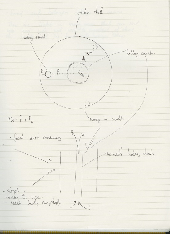
So Ives been tinkering away and have come across some issues that I carnt really get over.

Temperature sensors and their placement; Looking for a little advice here and feed back.

My original idea was to use a thermocouple placed directly before the material chamber as to provide the more accurate feed back for the controller. Here are my thoughts layed down.


Response Time:

Assumption: The halogen heating element is powerful enough that it can provide rapid response to a change in air flow conditions.

That is to say, as air is drawn over the glass surface, the heat is exchanged, the glass cools down, as the sensor reacts the system will try to achieve the set point. The responce time will be how long it takes for it to react from the initial inrush and bring the air temperature back to the setpoint.

I am arbitrarily setting a response time for 250ms. So it takes 1/4s for the air stream to dip then recover to its set point.

[Im trying to avoid the use of a hight heat mass (longer heat up time - aiming for no heat up time), though having one large enough to cope with the initial inrush from a pull might be necessary - more data is needed!]

Sensor:

Assumptions:
  • The heat mass of the heat exchanger is not large enough to maintain the setpoint through the entire draw.
  • The heat mass of the sensor will be a major contributor to the response time
  • The sensor will be placed in-stream to ensure accurate air temperatures

The sensor that has currently winning out in a platinum RTD, these little guys are highly accurate (+/- 0.5C), cheap and have a large support of dedicated sensing chips with spi interface making temperature reading fast, easy and accurate. (Currently playing around with a max31865, having a bit of trouble with the QFN packaging)

They are also glass coated and plan on using the bear sensor in the air stream to avoid hefty response time penalties of SS sheaths.


Placement:


This is where I'm getting tied up in knots.

Before or after the material chamber.

I am leaning very heavily towards placement AFTER the material, in my eyes, trying to get achieve accurate material temperature by placing the sensor BEFORE the material is always going to be a prediction. It can be assumed that after a certain time, the chamber and material will equalise and then will be at the same temperature as the income air, but to me, this is unreliable and there are so many factors that will contribute to fluctuating temperatures of the material, moisture content and ambient temp to name a couple.

This is all solved by placing a sensor after the chamber (ideally have two sensors to ensure the incoming air is not to hot as to burn the material)

Thought?


J
 
smokeliss,

Hippie Dickie

The Herbal Cube
Manufacturer
here are my thoughts based on my designs over about 14 years ...

i put the sensor (a k-type thermocouple) at the hottest part of the heater coil (nichrome 80, 16 awg) - this is the middle loop. i find the temperature in the bud does reach equilibrium quickly - within the first 5 seconds of the toke. so my sensor is outside the airflow and away from the herb.

the condition of the herb does affect temperature stability in that the temp will drift up about 5 to 10 deg F after 5 minutes into the session. i am assuming heat of vaporization and heat saturating the interior of my cube are sucking calories during the initial part of the session. once that is done, the temperature rises to what is actually the setpoint.

i really don't see any effect from ambient temp, which for me varies from 50 deg F in winter up to 90 deg F in summer - makes no diff the cube always performs the same.

you need power reserve to compensate for temp drop with air flow, but 70 watts (6v @ 12a) is more than enough. my code reads the k-type 3 times per second (using the MAX6675 with SOIC-8 package) and I am getting stable temps throughout the toke. i use a separate digital BBQ thermometer to display the temp of the outside of the glass air path, right next to the k-type. provides more of an average temp readout vs the instantaneous nature of reading the k-type. or so it seems to me.
 
Hippie Dickie,
  • Like
Reactions: smokeliss

Egzoset

Banned
Salutations SmokeLiss,

Thanks for attempting to implement what i once hoped could be accomplished with a modded Venus!!

:clap:

Your quest for simultaneous thermostatic agility vs precision makes me guess this may call for a solution based on 2 interlocked regulation loops: a fast one to monitor infra-red light (as it travels from the heater element to the optical detector instantly), while its slower counterpart would adjust some variable temperature "bias" reference using an ordinary thermocouple, etc.

Lets theorize a glass envelope around the tungsten (heater) element of any halogen bulb can't "follow" and reflect fast temperature variations. Well at least i know there's no glass layer in an Elevape Smart vaporizer, so maybe the manufacturer figured they couldn't solve this in presence of such a thermal interface inducing some delay in heat propagation, in a portable unit...

So, my guess is if 1 loop doesn't suffice then maybe 2 will do!

:peace:
 

smokeliss

New Member
The way I was thinking about going about doing this:

A thermocouple will be used to measure the temperature of the sheath around the heating element (300w linear halogen bulb). This sheath will form the outer layer of the heat exchange area, this will stay at the setpoint for standby/idle running,

The second sensor (platinum RTD) will be upstream, as you draw it will pick up an increase in temperature, switching the heating element control over to the upstream sensor, allowing precise air temperature control.
 
smokeliss,

Egzoset

Banned
Salutations SmokeLiss,

...thermocouple... ...sheath... ...heating element... ...the outer layer of the heat exchange area...

It all spells mass to me, which means delay which leads to overshoot wobble in a regulation loop, eventually, etc. Really that's for others to debate, though i was thinking the FlowerMate Vapormax V has a pressure sensor, i believe, so it's likely their controller incorporates some sort of pre-emptive correction signal for a 3rd nested loop, etc., whatever!

Go figure!!

:science:

Theoretically i'd suppose that specific delay can be made next to zero, just evaluate correctly what the energy output requirement will be according to monitored airflow, perhaps using software tools providing some electronic music-paper user-like interface, etc.

...second sensor...

A long time ago i read something about 2 sensors allowing measurement of airflow, in replacement of a pressure sensor i think. But temperature sensors have mass while a predictive estimate has none.

Your thread sure caused me to read anyway!

:peace:
 

smokeliss

New Member
Salutations SmokeLiss,
It all spells mass to me, which means delay which leads to overshoot wobble in a regulation loop, eventually, etc.

After playing around with PIDs for a bit, I found having a highly unstable constants leads to be better control of overshoot, to the point where it was
negligible.

You can use a hot wire or two temp sensors to measure airflow with some simple calculations, but at the time-being see no need to worry about mass flow if I have a sensor post material.

As for predictive algorithms, it to early in development to say as the air path has yet to be finalised, though my own preference is to avoid trying to predict the flow, but may be necessary.
 
smokeliss,

Egzoset

Banned
Salutations SmokeLiss,

...my own preference is to avoid trying to predict the flow...

Maybe the Elevape needed the pressure detector for additional purposes, in any case there's at least 1 other solution which needs no sensor, no algorythms, etcetera: i'm thinking the Curie effect could make all this obsolete eventually.

:peace:
 
Egzoset,

Hippie Dickie

The Herbal Cube
Manufacturer
@Egzoset - isn't the Curie effect a fixed temperature? How do you gradually increase the temp or set different temps for different effects or to extract specific cannabinoids?
 
Hippie Dickie,

Egzoset

Banned
Salutations Hippie Dickie,

...isn't the Curie effect a fixed temperature?

Indeed, when a Curie alloy reaches it's Curie point magnetic excitation energy stops being absorbed because the metal became "transparent" to it, essentially speaking. At least that's the theory, in practice there can be hot-spots which require to be dealt with using copper/aluminium cladding, etc. But this would apply to IH cooking pans while i wonder if that's a real issue when scaled down in size for our own favourite appllication (...); yet in simple terms we can reasonably assume it's offering "fixed" thermostatic regulation, yes.

:D

How do you gradually increase the temp or set different temps for different effects or to extract specific cannabinoids?

Heat-cycle stealing would provide access to lower temperatures using more traditional control techniques, though i'm starting to imagine perhaps an hybrid method would enhance/extend this other scenario, by using multiple layered Curie alloys in Russian Dolls fashion:

29ptg0o.jpg

Lets see if i can make sense at all... :science:

At first all metals are ready to absorb magnetic energy because they're all at room temperature, so if those different metals fully contain the previous one starting with the hottest inside then i presume that should mean you can't climb directly to that last Curie plateau: the outer shells will need to be made magnetically transparent before that last temperature can be reached. So there would still have to be a thermocouple sensor, to implement coarse control between each phase corresponding to the next layer...

So in other words i'd leave precision/stability matters to the point-of-contact instant-acting Curie effect, with a control box to gear between the various Curie points.

:D

Now isn't that wild?! A bit overkill i guess but since that's dabbing and hence it calls for power anyway...

But can this work?? Who's gona try?...

:peace:
 
Last edited:
Egzoset,

Egzoset

Banned
Salutations,

Before this thread gets moved for a lack of active dialog i'll finish it saying that 2 fixed-temperature references would still allow a whole range of settings through simple airflow mixing, e.g. the "analog" way.

:2c:
 
Egzoset,
Top Bottom