Are you sure? l’ve watched a lot of CFD stuff recently and there seemed to be a lot of math and predeveloped understanding of complex formulas involved. I don’t think it’s really anything as simple as photoshop.

-
SCAM WARNING! See how this scam works in Classifieds.
You are using an out of date browser. It may not display this or other websites correctly.
You should upgrade or use an alternative browser.
You should upgrade or use an alternative browser.
Arizer portable heater tech discussion
- Thread starter stickstones
- Start date
nms
Well-Known Member
I'm pretty sure no one said it was easy or didn't need work into learning the tool and background to use it. But it would heavily assist at measuring things that are hard to do otherwise, like volumes, surface areas and the interaction between the different materials at different air flows.Are you sure? l’ve watched a lot of CFD stuff recently and there seemed to be a lot of math and predeveloped understanding of complex formulas involved. I don’t think it’s really anything as simple as photoshop.
You can say using the software to do this is easy given how impossibly hard it is otherwise(only possible with a lot of averaging).
EDIT: Ok photoshop was a bad example since the UI is now very simple, use a parametric modeling tool as a closer example. You need to know the math behind the shapes, but you don't need to pre-calculate the math to create the exact shape you want, the toolset aids at that.
I'm pretty sure no one said it was easy or didn't need work into learning the tool and background to use it. But it would heavily assist at measuring things that are hard to do otherwise, like volumes, surface areas and the interaction between the different materials at different air flows.
You can say using the software to do this is easy given how impossibly hard it is otherwise(only possible with a lot of averaging).
That’s not at all what I’m saying, I’m simply stating that you would still need to be able to do the math for that to even be remotely accurate or useful. I don’t think it’s the kind of math you can just “play around with” you’re either in the pool or you’re not with this stuff.
Needless to say I’m not sure why anyone would possibly care enough to go through all that, but I guess it could be fun to show your engineering professor?
Farid
Well-Known Member
It's certainly more complex than Photoshop, but the actual calculation is done by the computer. You still need to setup the equations at play, but the computer does the most difficult work of combining different elements, that would be nearly impossible to do (accurately) by hand, even to a trained engineer.
If I had a CAD model of the SOLO heater already created this would not be a problem for me (besides the fact that my solidworks student license has expired). The difficult and time consuming part would be creating a CAD model that is a perfect representation of the SOLO heater. Making new designs in CAD is easy, but reverse engineering existing designs can be tricky.
This video is a great example of what's involved. In our case the fan would represent the airflow caused by inhalation:
Last edited:
nms
Well-Known Member
Ok photoshop was a bad example since the UI is now very simple, use a parametric modeling tool as a closer example. You need to know the math behind the shapes, but you don't need to pre-calculate the math to create the exact shape you want, the toolset aids at that.
Training a skill, learning new things and being able to understand the implications of it as future information comes in is quite the massive reason to me.(obviously no one is going through all this discussion to be an arizer fan boy, because no one that goes into this much detail cares much about what arizer does, is or represents. I do want to learn from what they did though and why they did it is a great start at that.).
EDIT: I can maybe get a CAD model for the heater built on 360, if there's no rush
Last edited:
KeroZen
Chronic vapaholic
that would be nearly impossible to do (accurately) by hand, even to a trained engineer.
You mean the modern lazy kind of engineer...
")
Don't forget architects in the past used to draw entire buildings by hand without any CAD software, engineers designed bridges that still stand today again without any kind of software.
So yeah in our case some flow turbulence can be a bit tricky to model but it's nothing near rocket science.
Farid
Well-Known Member
Even analysis of bridges and buildings will get a better, more accurate result using FEA (and those are much more static systems, meaning they're easier to evaluate). There isn't any hand calculations that will produce as accurate a result as the partial differential analysis done by a computer. Prior to FEA software these calculations always involved some approximation as well as real world testing (which opens the door for experimental error)
Simply put, FEA has revolutionized engineering, enabling accuracy that was previously unavailable.
Also, FEA has been used in some form since the mid 20th century, so it's hardly representative of the modern lazy engineer.
But most importantly, hand calculations would be of little value to this discussion because they do not come with visual models which can be shared on this forum. With FEA we can produce models which show the temperature changes, and airflow across time, allowing even a layperson to see and trust the results.
Last edited:
nms
Well-Known Member
I wouldn't call good modern engineers lazy just because they have the tools needed to push forward. They just have different concerns and their expertise is no longer focused on the same things. This is how we move forward. To disagree with you I'd call the air flow and interactions in this system not that different from rocket science, to be honest. And doing it by hand would be quite troublesome. You need to figure out the contact area, volumes, material properties and then instead of averaging the interactions based on simulation results you'd need to make an assumption or a thousand of them as to what would be the most likely ways for particles to interact.
When uncertainty is a problem the simulation will throw a massive number of possibilities to deliver a very reliable average scenario. You'd take a few years to get to the same degree of confidence on a result.
When uncertainty is a problem the simulation will throw a massive number of possibilities to deliver a very reliable average scenario. You'd take a few years to get to the same degree of confidence on a result.
Andreaerdna
If God is the answer, then the question is wrong
Could not agree moreI wouldn't call good modern engineers lazy just because they have the tools needed to push forward. They just have different concerns and their expertise is no longer focused on the same things. This is how we move forward.
That is the definition of the expression “standing on the shoulders of giants”

So yeah in our case some flow turbulence can be a bit tricky to model but it's nothing near rocket science.
exactly! i would like to see the math even for an idealized case.
also, i guess i still don't understand @OF comment about the temperature sensor probe draining heat away from the herb load ... here is my thinking: the 30 gauge (0.010") k-type probe has a maximum current capacity of .142 amps, so at 3.5 volts for a single cell, that is .497 watts, while it takes about 15 watts to maintain the 420°F needed for convection. but i doubt the probe is carrying any current to speak of, certainly not several dozen milliamps. so where is the heat going? or maybe that is NOT what he is saying and i heard it wrong.
nms
Well-Known Member
He is saying that the probe conducts heat away mostly through the copper cables that go to the probe, but this seems neglectible both due to the relative measures staying the same and the difference between the wider cables being small. I'm still trying to get an accurate model to share here for Farid to create a simulation.
Last edited:
OF
Well-Known Member
Yep, that kind of load. T/Cs actually measure the temperature drop down the dissimilar metals. They are shorted together at the weld (typically) 'where temperature is sensed' (the hottest place in that system) so the voltage difference there has to be zero? But a tiny voltage change per degree happens down both leads to the "cold junction" in the readout. This is why the leads have to be so long, so they are basically at room temperature before we change metals. Folks tend to think the signal is generated at the junction, but that's not the case.He is saying that the probe conducts heat away mostly through the copper cables that go to the probe, but this seems neglectible both due to the relative measures staying the same and the difference between the wider cables being small. I'm still trying to get an accurate model to share here for Farid to create a simulation.
FWIW, there are also "isothermal junction blocks" where the insulated (electrically) connections are thermally held at the same temperature where they change to different metals. Like if you were sensing temperature in a remote furnace using expensive thermocouple types (one is Platinum/Platinum alloy that's even more expensive), but we're not in that game.
The heatsinking issue was verified (both by me and others in this thread). If you look at the 'jump' with airflow (giving rise to the idea the incoming air was heating the load) when actually it's simply bringing the herb around the heat drain back to temperature. The test is to use different gauges of thermocouples in the same conditions. If you use finer leads (so less heat is removed) the jump is smaller. You can postulate that with zero diameter leads the jump also would be zero (makes sense, the load is in full 'heat soak'?). And the reading would be accurate for the whole load, not just the herb around the junction which has been locally cooled sending heat up the leads that aren't there. The original idea that there was convection heating happening (and the load dropped 30 or so degrees between hits) was an instrumentation error commonly encountered if the details of heat flow aren't taken into account.
A company in the trade, the leader, Omega, has lots of good information on this good stuff. They used to publish a catalog about four inches thick, well worn by some of us. Now it's on the web and confuses me trying to get information I used to be able to quickly find in the book.
Thermocouple Guide: Everything You Need To Know
A thermocouple is a sensor that measures temperature. It consists of two different types of metals, joined together at one end. Learn more this guide.
Seems a good place to start?
Edit: Here's a fun idea. The leads of the T/C don't have to be welded together. I've worked on tiny systems that have the (very fine) T/C wires spot welded to a SS, Inconel, Titanium or other high temperature heater body at different points, the body material doesn't matter since the ends of the leads start out at the same temperature.....which is what is indicated in the end.
Fun stuff, not as simple as it seems.
Regards to all.
OF
Last edited:
Farid
Well-Known Member
I’ve been thinking about how to make an experiment to determine if there is a temperature jump in the load upon inhalation (indicating convective heating versus convective cooling)
One idea I had was to use some kind of wax-like material that melts at a set temperature (say 330 ºF?). If this wax is then formed into some small spheres (essentially wax BBs) and loaded into a stem, it could simulate the restricted airflow which occurs when using bud. It would also be easy to tell if this wax has melted because upon melting the airflow through the stem will become blocked.
The question we will be trying to answer is: Does the wax melt upon drawing air, or has it already melted from the conduction through the oven walls prior to drawing air?
This won’t give a nice temperature time graph the way a thermocouple can, but it may be a simpler way to answer the question of convection heating versus cooling.
There’s probably lots of issues/errors with this experiment, I just thought of it, and haven’t had time to really think it through. But I wanted to share in case anyone had any modifications which could make it more effective.
Whether there exists a wax-like material that melts at such a high temperature is another question.
nms
Well-Known Member
I think that experiment would be particularly nice if we were discussing conduction vs convection but we're discussing if the convection effects are relevant here, because I'm pretty sure that given time to become a stable system, the oven gets to vaporization or very near vaporization temperature without convection happening at all. The convection happens as both a compensation mechanism when heat is lost in significant amounts and as an assistance to vaporization on draw. I believe that particularly in the oven center and when you are drawing air, vaporization temperature is maintained by convection. So what I'm arguing is that the device not only pre-heats air enough to prevent convection cooling from happening when inhaling, but also pre-heats air above oven temperature so that it contributes to vaporization of an oven that's stable at vaporization temperature, or very close to it.
The heat losses particularly through glass keep the chamber on idle at a stable temperature lower than the heater, which is far above vap temp, but also lower than the air which enters the chamber closer to the heater temperature. When such air comes in it transmits a small amount of energy, that given the current oven temperature(which I argue is lower than the air temperature and as apparently verified than the heater temperature) is just enough to contribute to the vaporization of some of the compounds. This is, in my opinion how a single heater system can be a true hybrid device. This is but an attempt at an educated belief and without the aforementioned simulation it's but an hypothesis that would seemingly integrate with the results seen in the experiments out of many others.
The heat losses particularly through glass keep the chamber on idle at a stable temperature lower than the heater, which is far above vap temp, but also lower than the air which enters the chamber closer to the heater temperature. When such air comes in it transmits a small amount of energy, that given the current oven temperature(which I argue is lower than the air temperature and as apparently verified than the heater temperature) is just enough to contribute to the vaporization of some of the compounds. This is, in my opinion how a single heater system can be a true hybrid device. This is but an attempt at an educated belief and without the aforementioned simulation it's but an hypothesis that would seemingly integrate with the results seen in the experiments out of many others.
Farid
Well-Known Member
That can be controlled for by pulling the stem out after the first hit (and after a set amount of time from a cold start). Leaving the stem in the oven of course will lead to vaporization by conduction. The question is whether convection can add enough heat to melt the wax.
nms
Well-Known Member
Enough heat excluding conduction, or enough heat including conduction? These are different things. Trying to vaporize a room temperature load by convection requires far more energy than vaporizing a load near vaporization temperature. No one ever said you had enough power here to vaporize herb from ambient temperature from convection alone, I think that's unlikely, but can't tell for sure, but from comparison to other devices I find it hard to believe. What I'm saying is not that convection is the only mean by which the load is vaporized, I'm saying convection plays an important role in the overall vaporization like on any other hybrid device.
Farid
Well-Known Member
Including conduction. You allow the stem to heat up in the oven, take the first, and only hit, and remove the stem. Then you repeat this, but do not take a hit, and remove the stem (allowing the stem to be inserted for the same amount of time as previous test). If convection plays a role in increasing the load temperature the wax should be melted in the stem where a hit was taken and not melted in the stem where no hit was taken.
This would take some adjusting to find a waxlike substance that melts at the exact right temperature (which would have to correspond to the temp the solo is set to)
This would take some adjusting to find a waxlike substance that melts at the exact right temperature (which would have to correspond to the temp the solo is set to)
Last edited:
nms
Well-Known Member
@OF just for you I ran a test on an empty bowl with the t/c as close to the center of the bowl I could get, which would be about 5mm from the floor of the chamber. Here is the chart:
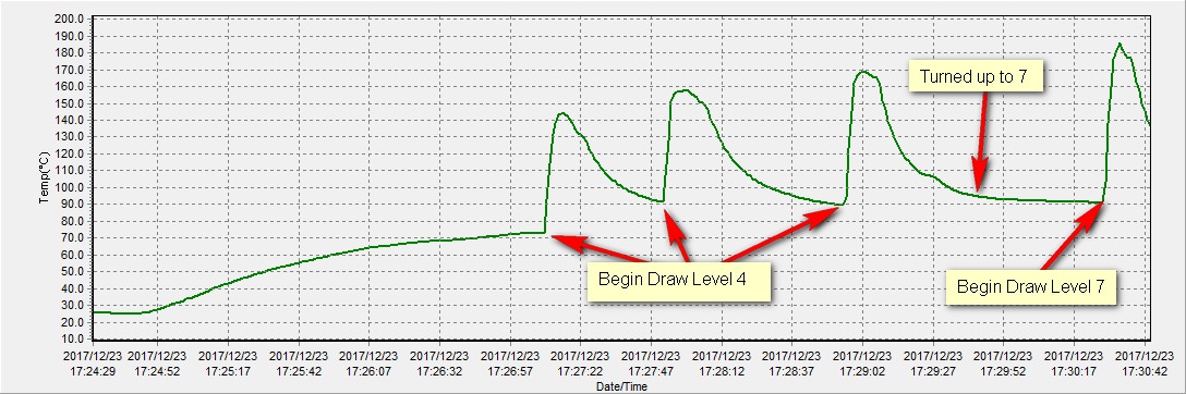
The temp increases during the draws demonstrate the amount of convective heat entering the chamber.

I tore into a Solo last night to help answer some questions. I placed a temp probe at the heater itself (the lower, smaller ceramic donut mounted under the bowl).
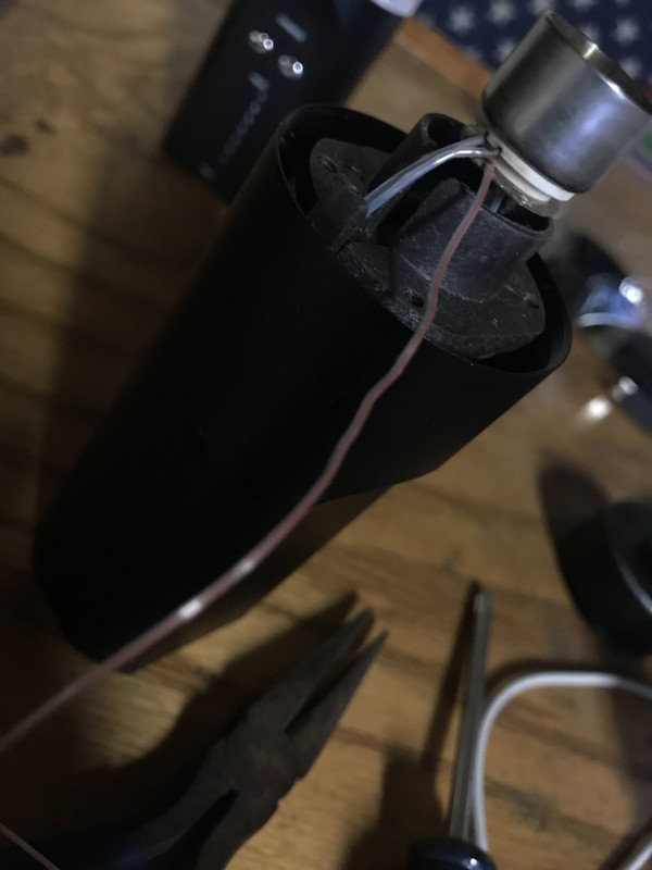
I then attached a probe to the floor of the chamber and heated it up.
Here is a chart showing the test up to temp 7.
The actual answer as you can see by the chart above is about 550°F which is about 170°F higher than the “cup”. This shows us that the hottest part is not the cup, it’s the heater.
I ran a test to demonstrate what is going on in the relationship between the heater and the load. This test was done on temp 4 with some sweet Jack Herer surrounding a temp probe in the middle of the load.
Once again, this clearly demonstrates the convection occurring during the hit. I think Arizer deserves a lot of credit for this design and to phoo phoo their accomplishments as some marketing ploy is not fair to them, and not fair to the readers of this forum that expect good information and not just guesses that are factually inaccurate presented as such.
Last test shows temperature in the middle of the load comparing to heater temperature. I find it really hard to believe that air plays no significant role in heating the load when looking at the limited evidence we have. If you look particularly at the last part of the graph, you see that by conduction we cannot maintain a temperature higher than around 165ºC and around that temperature it becomes really hard, in the center of the load with this specific herb to do so which given the oven being open(the glass stem for sure is a constant heat loss).
In the upper graph we see the thermistor reaching around 180º after some effort with convection alone, even if this is off by 20º, it doesn't mean that air indeed cannot be at an higher temperature than the oven in normal working conditions.
In the last of all graphs you can see that in the middle of the load conduction doesn't seem to be able to maintain the temperature above around 165ºC which is fair given that the oven is basically open as the glass will continuously pull heat out of the system and cool itself with the surrounding air on the top side.
Even in the first graph you can see that with some effort air is capable of heating the thermistor to around 180ºC and even if that's off by 20-30ºC which is a lot I find it hard to believe that in the complete system air is not capable of entering the oven at higher temperatures than what the oven is at, according to the evidence.
OF
Well-Known Member
In the last of all graphs you can see that in the middle of the load conduction doesn't seem to be able to maintain the temperature above around 165ºC which is fair given that the oven is basically open as the glass will continuously pull heat out of the system and cool itself with the surrounding air on the top side.
Even in the first graph you can see that with some effort air is capable of heating the thermistor to around 180ºC and even if that's off by 20-30ºC which is a lot I find it hard to believe that in the complete system air is not capable of entering the oven at higher temperatures than what the oven is at, according to the evidence.
Yes, the longer the heat path, the more resistance is added to the heat flow so there will be a bigger drop with the same heat (in calories, not degrees) being removed 'up the leads' since the temperature drop across them is about the same 320F? This can be demonstrated by moving the same thermocouple closer to the walls.
Good observation that heat is conducted up the glass tube, although at a slower rate than through it since the path is longer? This is confrimed by the experience that using Ed's excellent stems, which are SS, the working temperature has to be 'bumped up' to compensate?
There are, of course, a whole host of temperature indicating materials. Some with very high calibration. They range from crayon like sticks that you wipe on hot metals in heat treatment to paints you put on semiconductors to confirm they were never overheated. "Tempilaq" is a common brand line here:
I've got some around here at about 400F, which is why I'm so confident that the cup is indeed basically the hottest spot in the system. And as you say, unless there's a hotter place to heat the air, this is the hottest it can possibly enter?
You can also paint it on a bit of foil in the bottom of the load to confirm the incoming air isn't any hotter, of course.
Regards to all.
OF
nms
Well-Known Member
I can agree that possibly the fast lost in temperature in the thermistor after draw stops happens through the leads but how does this affect any conclusion? If there was heat in the chamber to compensate for this, it wouldn't be measured either, right?
Also regarding the SS stems, how do they fare subjective experience feel wise?
Also regarding the SS stems, how do they fare subjective experience feel wise?
Last edited:
There is no measurable heat moving "up the leads". If there were, then all conduction vapes would have a chart similar to Solo. The fact of the matter is they don't.heat (in calories, not degrees) being removed 'up the leads'
Here's a chart of the Haze V3 using the same t/c:
I welcome any measurable evidence that's contrary to my findings.
OF
Well-Known Member
I can agree that possibly the fast lost in temperature in the thermistor after draw stops happens through the leads but how does this affect any conclusion? If there was heat in the chamber to compensate for this, it wouldn't be measured either, right?
Also regarding the SS stems, how do they fare subjective experience feel wise?
It disputes the 'obvious proof' that the incoming air was heating the load. Folks saw the dip in temperature between hits, and rise back to 'normal' as proof the incoming air was again heating the load. A mistaken impression based on instrumentation error.
It was correcting the mistaken 'proof' of convection? Again, thinner (or thicker) leads give different results as does moving he same thermocouple closer to the wall.
There is no measurable heat moving "up the leads". If there were, then all conduction vapes would have a chart similar to Solo. The fact of the matter is they don't.
I welcome any measurable evidence that's contrary to my findings.
It depends on the vape and the way you set it up. If you dig back in the Ascent thread you'll find a series of tests I ran with thermocouples close to the wall that showed complete agreement (within a degree) of the display at idle (I was careful to leave lots of lead metal exposed to the herb) but I got almost 100 degree drops with hits. Worse than Solo by a lot since there was a slower 'recharge' path for the heat. This led to the use of glass flowers mixed in the load to act as 'heat reservoirs' giving much fuller hits by limiting this drop.
Regards to all.
OF
nms
Well-Known Member
What I meant was that after the draw stops and giving the chamber temperature is below thermistor temperature at that point, the heat is lost faster through the leads than through the herb. Meaning on the first graph shown on my post above(your graph quoted on my post above), the thermistor heat loss right after draw stop will happen faster via the probe wires than the air around the thermistor. This is completely irrelevant to the question at hand as far as I was able to reason about it though, just a curiosity.
For note and now that I think about this with some added math we're talking if we use a 1mm wire(I assume it will be smaller than this but for reference and then multiply by two for in and out) about a 0.00785 cm3 cross section. Also wire may not be copper.
q = [(385 W/m oC) / (0.05 m)] [(0.000000785) (0.000000785)] [(180 oC) - (20 oC)]
(Heat transfer (W): 0.484 over 10cm copper wire from 180 to 20 ºC on either end, ignoring losses through insulation)
For a 100mg thermistor(assuming made of silica), we'd get a specific heat capacity of 703 J\kg k. We'd need to looseit 0.0703J to reduce temperature by 1K\Cº. We'd be talking about a 2ºC temperature loss per second in this setup, very averaged. Also this is a curiosity because while temperature would probably be lost faster through the leads than through air, we're talking about something that doesn't affect the conclusions.
My math may be wrong, feel free to correct it. Keep in mind temperature should also be lost through air, so we should see this plus a bit more of heat loss. t
PS: Again you can get instrumentation error, but it will remain the same over the experiment, meaning the relative measurements will remain valid. All our conclusions are based on relative measurements, none of it needs an absolute temperature.
Also when comparing with haze, it seems more than reasonable to me that we see no convection cooling on solo 2, at least not in the draw time-range tested.
EDIT: Math updated
Last edited:
or, the heater is underpowered and/or the thermocouple/PID algorithm is faulty - i would guess the cell can't deliver enough amps on demand. i used to see this with a log vape with fixed resistance heater coil/fixed current power supply.... in the Ascent thread ... I got almost 100 degree drops with hits. Worse than Solo by a lot since there was a slower 'recharge' path for the heat.
i don't know what "slower recharge path for the heat" means - if the current is fixed then reestablishing vaping temp thermal equilibrium after being cooled by ambient air (toke), well, it takes some time.
i see 2ºF temp drop when my heater is off. not being drained by thermocouple wire leads - thermocouple touches heater coil, heater coil is attached to pcb, so pcb is cooling the heater coil.2ºC temperature loss per second
i finally tried to measure the IR heating of the load ... my conclusion: there is very, very little. the probe in the middle of the herb was 100ºF below the heater temp even after 10s of minutes. So, IR heating is insignificant, i think - which is kind of surprising to me: all the heat emissions are directed into the load, but there is a 0.5mm air gap between the heater glass (1.25mm thick) and the load glass (1mm thick), so even with no ambient air flow, the heat is contained to a very thin layer.
just some musing on a saturday afternoon, that seemed relevant at the time.
nms
Well-Known Member
2ºC/K is not the same as 2ºF and surely adding to that there are the unaccounted losses, like heat lost to air around the probe, heat lost to the load around the probe and radiated heat. Again this is just a curiosity that affects nothing. Just clarifying the amount of heat that is actually lost through the probe wires in an ideal scenario.