VapCap DIY Induction Heating : Bits 'n' pieces

TommyDee

Vaporitor
I think the MOSFET is on the board like Pipes' module. This will make it easy to wire in a switch. I may re-purpose the power switch as a momentary fire button.

This makes it a PSM in a different form-factor. Alpine has coffee-table appeal which is exactly what I'm looking to do for my non-participating wife. I'll enjoy rebuilding it :nod:
 
TommyDee,

TommyDee

Vaporitor
Damn! Finally! 2 in-tact ZVS modules! And the DC-DC converter with the remote knob. Looks like I'll finally be busy this weekend.

On the agenda: a mini output version HalfPint with half the components, and a 3S desktop battery version that will rival the Aspine 2020 looks.

What makes these different?

The HalfPint - an attempt to make a generic input IH wand. Power it with 'anything' to suit your taste. Portable on a cord; connected to a brick; wired to a variable voltage base station; pocket power pack; the dual voltage SpikePack; or the car's cigarette lighter. HalfPint is intended to be your 'pocket IH' like a lighter. Just plug it into one of several cords laying around the house. The brick cord lurking about the couch; the tabletop base station on the dining room table; the lighter cord in the car; or that battery pack you have stashed next to the bed. Basically, you only have to carry around the 'lighter' in the form of an IH. Just give it juice. HalfPint is based on the circuitry of the Apollo 2 meaning it is half the ZVS circuit in component values.

The Coupler is a 3s 18650 concept that uses protected 18650 vape batteries. It is primarily a device that makes people ask what that is. The same impression I got from the Alpine 2020, I want this product to exude this mystery as well. The Coupler should sit on a dining or coffee table and own it! The unit will have a dual fire function as the new Flix has finally incorporated. the key element of this device is that it will be dual voltage. It will either fire with 3s or 2s depending on the user button selection. Basically, cook the load at 3s and if you want to, do a real-time on demand draw at 2s just to get that little extra edge. It should also actually be cubical as in equal size in all 3 dimensions and at least square in the planar dimension if the height is off-putting. A unit like this will hold a charge for days; charging is done with any regular 18650 flashlight battery charger; A deluxe version may have alternate charge options. Basically, I find a charge routine overkill when all I have to do is change the batteries like I do with flashlights. The batteries should just be easy to get to in the design.

I am sold on using protective cells. This takes 90% of the safety elements out of the device and lands them squarely on the quality of the cells you buy. They cover a) Fuse b) over voltage protection c) under-voltage protection d) over current protection. Quality 8 amp capable 18650 cells are readily available. I have some with a capacity rated to 3500mah. And for the best part, these can also be charged using a BMS as normal. The thing about protected cells is that they are 1-2mm longer. Most standard battery holders won't accommodate the protected cells. Definitely not the Chinese plastic holder.

The HalfPint is the least defined product from an industrial design standpoint but the concept is solid as the new Flix reveal already bears out. The Coupler is pretty straight forward. I envision a board with everything and no wires like the Apollo 2. A board with cells on one side and components on the other in a compact arrangement. Basically a self contained brick that needs a housing. This could well be the level I take this product to and let packaging go to the better artisans among us.

Again, I have no desire to go and make things again. But having boards made and having them stuffed is a simple thing and not very costly. I could see a good market for a battery powered IH sold like the ZVS modules are. Design services are free in this case since I have nothing better to do for a while, it seems.

Wish me luck on the HalfPint. That one I want to see running ASAP.
 

TommyDee

Vaporitor
That's what I've boiled all this down to anyway with all your guys' help. :tup: At least I can get moving again. That hiatus was too long between shipments.

:spliff: The base station, The Coupler, can have the plug-in for the HalfPint w/ 8v output. That means, of course, the Dee...Lux model is a dual IH. :party:
 
Last edited:

TommyDee

Vaporitor
It works. Insanely, it works -exactly the same-. One cap and center-tapped inductor.
Self power draw is 8v, 0.8a; 9v, 0.9a; 12v, 1.2a. I shit you not.
At a full 12 volts at the IH, this thing is as hot as any other I've built. Maybe hotter.
The only thing I can think of that all I've done is doubled the operating frequency.

49831805072_268998b5fa_z.jpg


49830960053_759d303dd1_z.jpg


Does anyone have the output rating of the power brick used on the current Apollo 2?

So I'm sitting here, high of course, and I am wondering why the mosfet switch. I've wired this up so the IH Fets are also a switch. There is no reason I can see to put a fet switch in front of a pair of fets. Basically, I am feeding plus voltage directly into the inductor. There is no closed circuit between this and ground. The Fets are open at this juncture. All I need is the gate power activated which is what we do when we activate the mosfet switch. Rather than pump all the current into the gate circuit to also feed the low impedance circuit, why not just switch the low power control circuit. On the ZVS board, that just means cut a trace and hardwire power to the center of the two inductors, or as I've done in this circuit to run a signal wire to the only positive trace on the board. The high current goes directly into the coil. Now I know why that switch has always bugged me. Maybe the mosfets switch fets are better on quiescent current making battery versions less susceptible to jewel thieves?

Edit; sure enough, now that I have a solid line of positive going to the centertap of the inductor, the 'enable' switch doesn't need to carry current. Cut the trace just outside the input connector positive (the trace that crosses the board under the caps). Now apply positive to the 3-pin output connector. Pick up a switch tap on this connection as well and connect to your momentary IH activation switch. The other end of the switch will go to the positive input terminal. All you've done is disconnect the input + terminal from the actual power input plus terminal. No current will flow unless positive is applied to input + terminal exactly like the MOSFET switch.

And for the obvious question; no, the coupling of the '20-M is no different.
 
Last edited:

TommyDee

Vaporitor
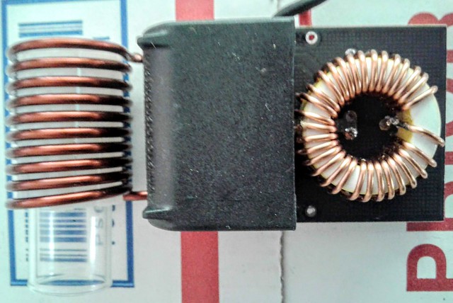
Coil work has commenced. This must be the tricky part. I've used stock coils since I started this project. They are heavy 12 gauge coils ready for some serious duty. They barely get warm enough to worry about on an open frame device. They are quick to heat the VC and they are dirt simple. The hardest part of this project is settling on an orientation for the coil and a means to hold the elevation of the VC.

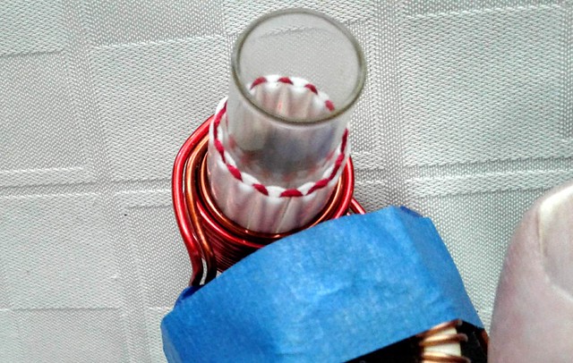
I wound a 9 turn 14 gauge coil some time ago. It has no insulation so I made sure the coils were well separated. I put a glass vial inside the coil to keep the VC from shorting the coil out. I centered the tip in the coil.

First of all, damn these smaller gauge coils get hot! There are a couple of things at play here. The coils are basically a short circuit to the circuit itself. There is N amount of resistance and the power imparted is basically the current running through the coil minus inefficiencies. Changing coils changes these characteristics.

There is no way I can run this 14 gauge coil in an open frame. Simply too hot. Could make a bud roaster out of it though.

Now I'll mishmash a few thin gs together to compare. I was getting about 13 seconds on the baseline model with an aggressive heating. Centering the cap in the coil. The coil is way over-sized and this adds to the impedance. I was getting readings in the 0.05 or less ohms on MODs. This is pretty much a buss bar across the output. And because it only gets warm, it is a fairly stable load as well. This setup pulled about 60 watts.

First round with the 14 gauge coil was interesting. 16 seconds to the click - 8 amps of current draw as opposed to the previous 6. Something is pulling down my input voltage in the setup but I was registering 72 watts. More energy and a slower click. Remember the circuit is very different also being cut in half.

Also consider the extra heat imparted to the coil. Copper changes resistance with heat. Therefore the circuit "weaken" as the coil warms up. It is always good to have a stable heater. I will see if a pair of 15 gauge wires will equal the 12 gauge performance. The circular mils should be equivalent. I think I will also opt for a longer coil. Looking to 'untarget' the heat a little. A larger diameter is definitely called for.

The VC got hot in the 16 seconds. Very Hot! As did the coil. So I adjusted the cup to be nearly level with the bottom of the coil instead of through. That went okay. 10 seconds to the click and a nice well cooked load. So this is the second thing I am not to sure about going this route. It is much more finicky.

Putting this in a safe housing will alleviate some of the heat concerns but it does require thermal fusing if that is the route. And the power level I'm seeing now is alarming. I need to see if this is something about my connections.

Take away so far, tuned coils are a liability. I don't really have the tools to take on this level of development to anything meaningful. This very quick little overview experiment was more about the right questions to ask than present any real data. Heat, stability, target heat zones... now those have all come into focus from this quick study.

----------------------------------------
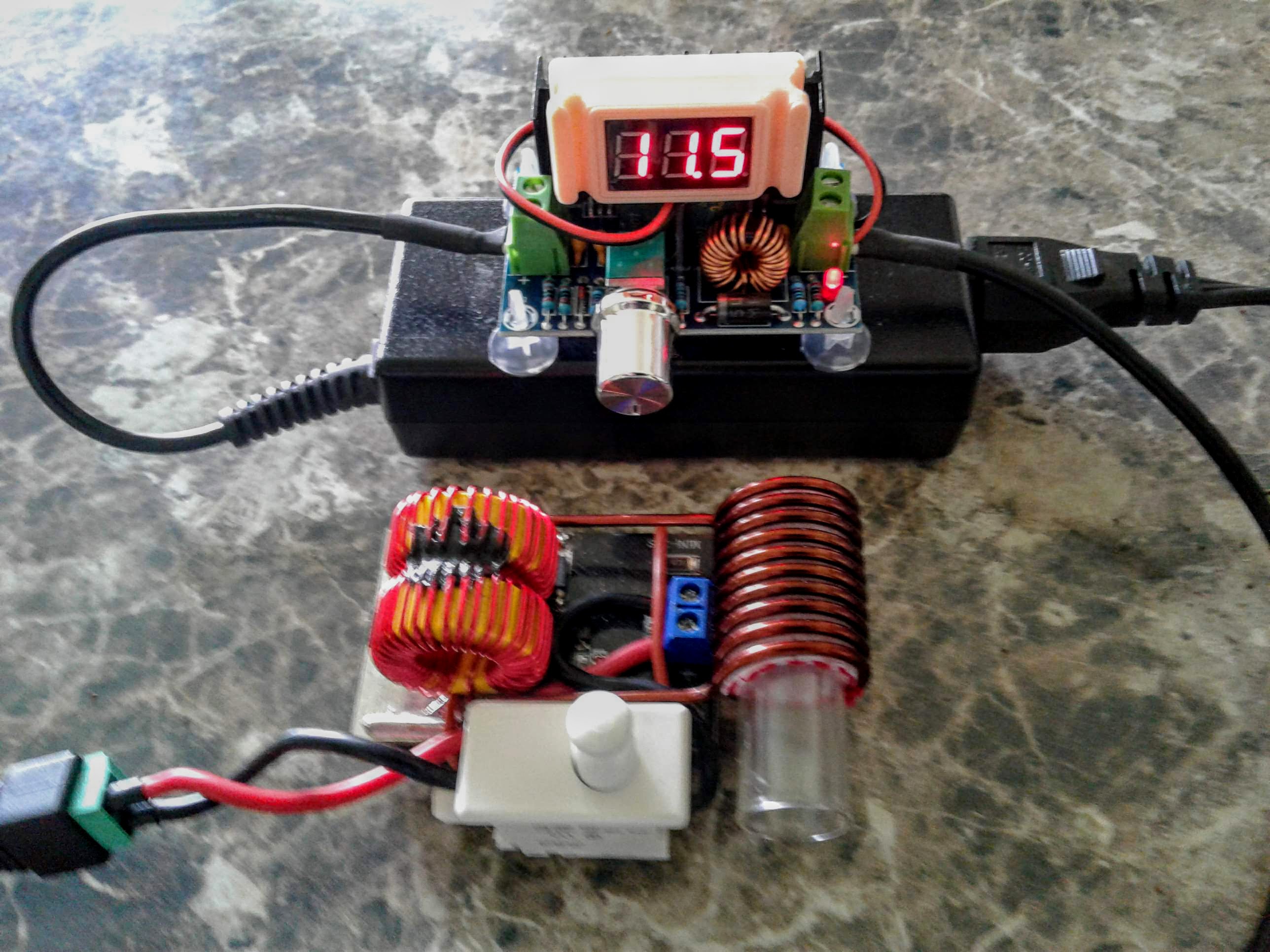
And to continue. I rebuilt the Half Pint back to the original coil. I also arranged the remaining components a little logically and robustly. Please remember that this is just a proof of circuit module. I am short on salvage switches so the little green dot is just soldered in activating the circuit.

49835498127_bc90538381_z.jpg


Notice the center-tap that is wired back to the board. It doubles as support and a positive binding post on the opposite side. The hole is only good for 18 gauge.

I cut the trace as I talked about earlier. Now I see I could have bridged the switch across the single hole (+) and the double holes that the small red with is going to. I may still do something like that. Basically cut the trace and install a tactile switch directly to the board.

Also notice the location for the negative power trace. I don't know about you, but these traces appear to be resistors. These are meant to carry 10 freaking amps. I'm going to have to look up some design rules. However, I opted not to use the thin traces for both plus and minus. Plus goes directly to the inductor center-tap and the negative is directly connected to the trace that joins the two MOSFETs. There is no other place to make this a good solid connection without trace losses. Just so you know. Even the via's are seriously lacking. They work, but why not improve things. So I have my ideas for the next go around but this is a nice little, and I mean seriously trimmed down, induction heating wand, albeit corded.

49834655373_1812c3bae7_z.jpg


Performance - FUCK THIS! <slams door and stomps off> respect to the makers. Seriously. I am not an EE. I tinker around and know more than enough to be dangerous. But this circuit doesn't behave according to the rules of logic. The new layout is far more efficient than yesterday. There is no change other than physical location of the components and their orientation. This layout is very tame, yet you put 12.6V on it and it will roast your bud. I'm having trouble getting 60 watts out of it, which is a lot, don't get me wrong. The 7.2V output is only 21 watts and 4watts of that is housekeeping. Therefore this test also shows that the usable voltage range has been narrowed or at least shifted. This unit will require a 3s cell arrangement if not a 12.6V brick straight up. I'll have to follow up with some power numbers.

Overall this thing performs. It provides a smaller package by droves and the removal of the MOSFET switch just simplifies life even more.
 
Last edited:

TommyDee

Vaporitor
Well now, based on findings yesterday, this requires some rethinking. The query of stability came about yesterday as one of the questions to ask. And I asked. Funny how the only voices that answer are in my head alone. Nevertheless, at least they answer and they have pretty good ones. Most of all these texts are based on those discussions. Sanity is only a measure of norm, BTW.

The big takeaway from yesterday's build and comparing it to the base ZVS module is that the output is reduced. Not by half but by a significant amount. Enough so that 8.4v or the lesser, 7.2v is insufficient for a reasonable heating or enough power to do on-demand draws. At ~20 watts, this is a real slow cooker. I worry more about lost vape than being able to chase flavor in the open vapcap design. If you see smoke, it's vape. On the plus side, 9v, the cutoff for a 3s cell arrangement, is perfect for on-demand. Pump that up 1 volt and you have a good 12-15 second cooker for the SS VC. Deep insertion will guarantee a good hot load.

Small changes of the insertion depth of the VC now make a bigger difference than noted in earlier full-complement units. I move the vial up and down in the coil to change the click and the temperature profile. Having a constant voltage is important for consistency. As the performance curve has tightened the available voltage range in this configuration has also been further limited. The variable voltage of a 3s li-ion pack, from 12.6v to 9v is a much greater range than one would want in this HalfPint device, or 'depopulated' device. I'd say that before significant coil changes, 11-9 volts is a very good range between 'heat me now' and 'heat me while I draw' temps. If this were to happened as cells deplete, the user experience would be less that optimal.

The HalfPint needs regulated voltage. Whether on a cord or handheld standalone, this circuit does what it must in regard to reducing the bulk of the IH to a portable handheld level device with manageable bulk. A proper battery pack should be commensurate with the device. However, on these new findings, it is also incumbent up such a device to have a constant voltage option to allow the user to dial in an exact experience. This is achievable with today's MOD tech. It is likely a slim boost driver that will manage 2s 18650 for a mild boost to drive the IH. The aim is On-Demand at 9v volts where a push to 10.5 volts would make it a conventional heater. The MOD could present a safety timeout at a minute or so as a bonus. Of course, use of a base-station would allow the user to dial in the exact power level they come to know and love.

The HalfPint as a wand on a cord is still attractive. We're down to a super cute small size while remaining a very potent heating element. A base station could be AC or just a mass of cells. I am not a fan of AC devices. Therefore a base station will have to be a DC device that will accept batteries or a 100w power brick. We've talked about protected cells. Still on that kick. And I got the latest 200w DC-DC converters that has a range switch for 12v, which should extend my potentiometer range. Testing on the previous device shows no heat concerns with the regulator for use with heating vapcaps. This is the part than needs to be miniaturized to the size of a MOD board. Also very doable. I've ordered yet another meter that should do well on a base station - it includes a 'watts/hour' display.

s-l640.jpg


This meter and the knob for the converter is sufficient to make a base station. Add a battery holder, and you have a portable base station. Plug in the power brick and you have a base station with a cord to the brick, which in turn has a cord to the wall. We want it all, right? Well, one more thing the base station should have ; another IH dialed to hot.

Two IH's? What the hell! He's gone loco! Haha! like fox. I've come to this analogy. we want a game changer. But more than that, don't fuck with our vape session!

What good is a wand when you have to change the dial. You are dialing the wand in for on-demand. One will want 9.2v and the next person will want 9.7v. Constantly changing the dial back and forth between 11v and 9.x volts is not user friendly. Not even presets will save this process. Dial and save the position. Just do the session with the vape, not the fucking box.

So what's with the second IH? Your initial heat-up, basically. Let this second IH follow the battery voltage using the more forgiving standard IH model. It will heat fast and give you the conventional session you are use to. Once heated and drawn on, use the wand to keep the heat signature consistent. Go ahead, finish off that cap, if you can.

What makes this a game changer? On-demand IH heat using draw modulation to control the temp. Early convection vape stuff. You also get a real time read-back of the conditions of your IH so you can duplicate the setting any time. And you get adjustable regulated voltage to the IH in a battery device that lets you dial in your VC experience.

This direction -is- the next big thing in IH and VC. :cool:
 
Last edited:

TommyDee

Vaporitor
This is my new favorite candidate for the portable base station read-back display.

2b90efb4-3e80-4589-ba6f-b0d51e206d6d.jpg


The screen is sizable and quite easy to read at 2" w x 1-1/4" tall. Backlite optional with the button press
The specs include 20 amp max and 100 volt max and minimum input is 6.5 volts. Perfect to range a set of 18650 cells.
With protected cells, this unit is more than up to the task of passing current and doing the analysis.

The case is a nice tough. Not required. The unit is actually very slim sans the connector. This might be easy to install as a design element rather than the plastic bezel. The core element has 4 screws attaching it from the inside.

There is a settings page. Very cool! Didn't know it was there. You can set up a low and high voltage alarm that flashes annoyingly if you are doing something stupid like not charging your cells or you are using the wrong charger.

And the Wh hours reading is a not exactly what I was hoping for, that being a 'how much vape you drew' meter, but it will tell you when your cells need charging. It is a running meter of how much power has been used since you last reset the meter. A very nice 3s set of li-ion cells is almost 39 watt/hours. 4s, 51.8Wh. 4s2p... etc. This little meter could be a very good battery monitor. To reset the Wh meter, you do a long-click thing and a confirm click.

After some input for very hot IH for concentrate, I think a 4s pack is still the way to go. I think I have all the pieces now.

For the record, this was $11.99. They should be showing up in droves. This is a perfect tool for DIY builds that use a lot of power.​
 
Last edited:

TommyDee

Vaporitor
Progress! :rockon: Finally did something with the 15 and 14 gauge magnet wire. Would be shame for it to go to waste. So I came up with a plan -

The original wire appears to be 12 gauge. When you pair a pair of 15 gauge wires, you get the equivalent of 3 gauges over. In this case, 2 15 gauge wires will have equivalent impedance to a 12 gauge wire. However, these things are balance-sensitive and the outside coil is a lot longer than the inside coil. Solution, 14 gauge.

Size, I did not change the ID of the coils once the spring was sprung. Nice as that did allow me to seamlessly transfer the vial and its collar. I 3D printed a tool to help wind the coil on the lathe. The 14 gauge wasn't very well wound on the bobbin. Came out pretty tight non-the-less. This is a freestanding height compared to the stock one;

49872450192_27b98202e8_z.jpg


The coil still remains touchable during firing with and without a VC. I haven't done analysis on it yet as this is hardwired to the battery pack. Hits like a tsunami! I'm almost afraid to see the standing power requirements.

49871608313_20efa13673_z.jpg


This satisfies my direction for the pocket IH wand. The HalfPint. Now it needs a better case and a wooden cup. I could not have the coil getting hot. Having mass while maintaining reasonable resistance is a means to manage coil temperature.

Even with the cells needing a charge twice a day, this little bugger cooks nicely. [charge cradle!]

I have some 12 gauge on the way for a more sustainable build. But I do look forward to seeing how this performs on the meters.

Other good news is that there is some movement on a battery front. Seems efest and keeppower are in fact introducing 1200mah 18350 cells. They run around $15/cell atm. I remember these wars with 18650. I might have to rethink my power strategy and aim for these on a layout. Makes adapting BMS easier, although I am avoiding that in the unit itself. Bottom line, 1200mah in the HalfPint would be a full day's charge for me.
 
Last edited:

PKOK

Well-Known Member
Dang yall been busy :D:D I like that meter but even more so..that sled holding the module. Printed?
Stuff is looking Good TD. What happened to the 2X 14500 approach. Hey I am still waiting on parts, missing the halo switch and M/F power ports but everything else is here
 

CaleidosCope

Well-Known Member

Dear TommyDee ... you made my day - week --- next month! ;)
What a curious, brave and lucky man. Just to prove the concept... the footprint is small. Tiny. And it performs! My footprint could be smaller, some mm here an there. I appreciate your thoughts about minimising the setup. Consider pluggable switches on the circuit board.
Thanks again. Hope u are well there overseas.


Jeff S

Well-Known Member
This was easier than I thought. Also better than I thought;

49732316332_1fba4d5b57_o.jpg


The converter came with the little mounts. I have some very double sticky foam tape that will outlast the mounts to paste the unit to the top of the power supply.

The power supply rating is 65 watts. The cord is a coax cord with a decent wire gauge, maybe 18 gauge. It is well over a meter long at this stage.
The regulator has very little adjustment range for this application. For that I will need to do some custom potentiometer work to get it in a decent range where over and under voltage can be avoided. For now, I added a volt meter to the connector to adjust it.

Full power, 12 volts, is not possible with this power supply. The regulator just shuts down. But I did get well over 80 watts out of it at 11.5V! That is impressive! Obviously stressing the power supply to that level is not warranted or necessary. But it does say a 90W or 120W supply is more realistic for this application. I'm loosing less than a volt across all these connectors and the long length of wire. That is pretty good in my book.

However, now that I can rightfully experiment with on-demand IH with adjustable power levels to the IH, I think this corded solution is the easiest and cheapest way to step up the IH to the next level.

Your next $25 IH

Why is this unique? Sure, you can wire a 12 volt brick to a switch and make this go. This little DIY trick is to provide adjustable power to your IH. This is specifically designed to dial in the IH to serve your preference.

49732424096_72d184fc00_o.jpg

Shown is a 65W power brick salvaged from a laptop obsolescence. $10
DC-DC converter, 200W. $4
Volt meter $1
ZVS IH. $5
Momentary 10 amp switch. $4
Connector, wire, misc.. $1


Hello guys, I have been following the thread from the beginning and you guys are great at DIY. I am tinkering with building a convection dry herb vaporizer. First I was going to use an old ATX computer power supply, but seeing this I have changed the plan to use an old laptop PS. It outputs 18.5Vdc and 6.5Adc. I like using my Zues acr gt but it's conduction and a mighty is too expensive. I plan on making a 75mm by 10mm aluminum air path to be heated with IH. With the output cable from the PS being 1.5m long will provide plenty of freedom for a hand held vape housing the IH gear for vaping at home. In addition to all the good stuff you guys have done I want to add a temperature feedback and display it along with voltage and current, to dial in the desired vape temp.
 

TommyDee

Vaporitor
Looking forward to your build @Jeff S .

Okay, I give in. What is the source for some of these glass coil liners you guys have on hand. Interested in the 16mm OD pieces, not too long. Thx.
 
Last edited:
TommyDee,
  • Like
Reactions: Jeff S

babunja

Member
hello everyone, I'm trying to figure out if it was possible to create some kind of IQOS using IH, IQOS uses induction to heat a foil inside the vaporization chamber. I wonder why it wouldn't be feasible to maybe use a glass tube like the cheaponic with a SS wire inside. It would be so compact if IQOS could be replicated
 
babunja,

tgvp

Well-Known Member
hello everyone, I'm trying to figure out if it was possible to create some kind of IQOS using IH, IQOS uses induction to heat a foil inside the vaporization chamber. I wonder why it wouldn't be feasible to maybe use a glass tube like the cheaponic with a SS wire inside. It would be so compact if IQOS could be replicated
I don't know the way iqos heat he tobacco, but I know there is some kind of metal wire inside the consumable (the "cigarette") and wonder if it's not what is used as a heat source while the iQos device may be a compact IH?
 
tgvp,

babunja

Member
I don't know the way iqos heat he tobacco, but I know there is some kind of metal wire inside the consumable (the "cigarette") and wonder if it's not what is used as a heat source while the iQos device may be a compact IH?
exactly there is an aluminum foil, which is positioned inside the chamber together with the tobacco, in this way little energy is needed compared to heating a vapcap for example and can be more compact
 
babunja,

tgvp

Well-Known Member
Just checked on wikipedia, iQos works by heating the device in which a "cigarette" (a stick of glycerin soaked tobacco ) is inserted, the one using induction is Illuma.
I don't own an iQos, but maybe it can be hijacked to be a heat source for weed, the problem being how to check temperature
 
tgvp,
Top Bottom