E-Nail from scratch

ak1016

Member
Hello, I got my first enail about 6 months ago - A cheap imported unit from a headshop near me, and quickly decided that I wanted to build my own PID controller from scratch, integrated into a coffee table.
Here is a photo of the prototype on a breadboard:
1j5xcwz2efq41.jpg
I'm posting here both to share my progress on the project and also for any feedback other people might have about the design. Here is a photo of the control flow in node-red as well as the dashboard itself:
qWsUsOy.png

X2oQuU0.png

(Yes, I'm aware of the wonkiness with the smoothness of the output, my D term is way too high, and my whole loop is quite poorly tuned.)


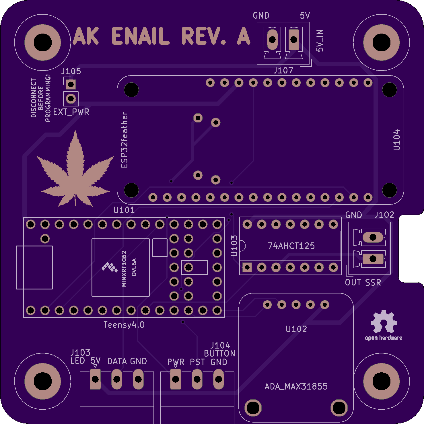
Finally, here is a link to the github repo with the code and early drafts of the PCB:
https://github.com/tobycyanide/teensynail

I'm posting here for feedback, suggestions, feature requests, anything you would like to see. I plan on releasing this completely open source - anybody who wants to build their own can for around $100 USD, but I will also possibly be selling finished versions. I have very little experience with most of these technologies, having toyed around with arduino in my younger days a little but that's about it.
 

TommyDee

Vaporitor
Last 2 images show broken.

Maybe a clear introduction what makes a PID controllers unique and how this uniqueness translates into better nail performance. I am aware of this but it is not as straight forward as many think.
 

Cheebsy

Microbe minion
I Love seeing a project using an esp32! I'm looking forward to seeing it progress. I have some devices using mqtt already and have thought about the possibility of integrating home vape devices with smart technologies.

Good luck!
 

ak1016

Member
I got siri integration working, as seen here:
https://imgur.com/a/0etWFxf

I've switched away from node-red to a home assistant instance running on my laptop, but have a raspberry pi 4 coming in today to run hassio, which should be more powerful and responsive than my Pi from 2013 running node-red.

Other updates - working on alexa integration, PCB design, enclosure design. I might want to build this as a modular enail, to allow people to attach screens if they would like, but my UX design involves some leds, a power switch, and a button to switch presets. Everything else I can control from a device, because my temp setting for me should be a set and forget type of thing, not something I want to constantly look at.
 

ak1016

Member
Got Hassio setup on the raspberry pi, now have full integration with Siri, and have done some networking setup to make it accessible at a fixed DNS name over SSL from anywhere in the world. Unfortunately, my router doesn't support NAT loopback, so I am now also running a DnsMasq container on the pi, which redirects requests to the dns record back to the local IP of the pi on my network. I could have avoided all of this by using Home assistant cloud, but would rather not pay a subscription for something I can do myself.


Other updates:
PCB and enclosure are coming along. Using a Schurter fused and filtered IEC inlet, genuine OMRON SSR, Mean Well 5V PSU, shooting for long-term reliability here. I'm planning on having 3 connectors at the front of the enclosure, all industrial connectors from MISUMI. One which pigtails out to the XLR connector on the table top, one for LEDs, and one for 2 buttons at the front, and if I want to add more controls later (like a screen or something), that same connector footprint can take a 4 pin connector with the same shell size for power, gnd, and i2c signals.


Less busy this week than I have been recently, hoping to get significant progress made. Next steps are making the communication protocol and state management on the ESP32 and teensy more robust, tuning the PID loop once my new coil and banger from 710 come in, and then LED animations. I'm thinking of having the middle LED indicate preset, and if a preset is not set to indicate that, and then have the ring of LED's around it be a function of the sign and magnitude of the error between the set point and the thermocouple reading. As usual, all of this is up on github, and I'll put the files for the enclosure up on git too.
 

ak1016

Member
I looked into ESPhome when I was starting to try and integrate home assistant. Because the peripherals are more complex than simple GPIO, especially with the ESP sending encoded messages over serial, I decided that it made much more sense to go custom/mqtt. The code has really not been that difficult, most of the heavy lifting is done by the nanopb, mqtt, and PID libraries. Also, here are some images of the enclosure. I'm going to be putting together a BOM soon to centralize all the parts I need.


ak1016

Member
Just ordered the boards and some misc. parts for the prototype. Still waiting on my coil and banger from 710, and got my pearls and spinner cap in yesterday. My friend is 3d printing me the case, and that should be done in the next couple days, and then I have a lot more work to do on the table. Here is a photo of the front of the board:
45e9959b0917d6323ffa9481f4bae075.png
 

ak1016

Member
Just some ramblings about ideas for the next version:
I would like to integrate all of the components onto a single board, to greatly reduce part count.
The next version is likely going to be an ESP32 application processor with a small cortex ARM core running some extra safety interlocks.
All of this will be open source for people who want to build their own, including code, PCB files, BOMs, and chassis STLs, however I do also plan on making and selling these, especially helping people integrate them into their own projects.

Please do let me know if there are any features you would like to see me add to this or future versions. I need to get my PID parameters rock-solid and still have to refactor some of the code that handles the protocol between the two microcontrollers, but here are some of the next planned features:
- Have LEDs show whether too hot/too cold/just right, as well as preset.
- Have a switch and a button mounted remote to the enclosure (See J104 in schematic above) that control the preset and power mode.
- I would like to add a screen in a future version, for if I build more of these for around the house and want them to be more stand-alone, and also because people have asked me if I would be adding a screen. Probably going to use an OLED panel, I've been thinking about those circular OLEDs that they use in gauges.

Once again, I need feedback from the community to make this project the absolute best it can be, so if there's something you hate about it, I'd love to know that too!
 

JCat

Well-Known Member
Accessory Maker
Just some ramblings about ideas for the next version:
I would like to integrate all of the components onto a single board, to greatly reduce part count.
The next version is likely going to be an ESP32 application processor with a small cortex ARM core running some extra safety interlocks.
All of this will be open source for people who want to build their own, including code, PCB files, BOMs, and chassis STLs, however I do also plan on making and selling these, especially helping people integrate them into their own projects.

Please do let me know if there are any features you would like to see me add to this or future versions. I need to get my PID parameters rock-solid and still have to refactor some of the code that handles the protocol between the two microcontrollers, but here are some of the next planned features:
- Have LEDs show whether too hot/too cold/just right, as well as preset.
- Have a switch and a button mounted remote to the enclosure (See J104 in schematic above) that control the preset and power mode.
- I would like to add a screen in a future version, for if I build more of these for around the house and want them to be more stand-alone, and also because people have asked me if I would be adding a screen. Probably going to use an OLED panel, I've been thinking about those circular OLEDs that they use in gauges.

Once again, I need feedback from the community to make this project the absolute best it can be, so if there's something you hate about it, I'd love to know that too!
- PID settings should be adjustable both:
a) manually
b) through an auto-tune
- API to control device through some form of connection, whether it be bluetooth, network, serial, other, ... (I'm assuming you already have this in some way? to control set temp? output current temp, status, etc.?)

Just some thoughts. I like your integrated board ... if the PID is solid with a solid algorithm, and rich features like auto-tune and robust safety controls, then I would consider modifying my code to run this as opposed to running the Omron E5CC through an RS-485 interface for advanced functionality ...
 

ak1016

Member
@JCat - Had seen your enail previously, was a big inspiration but wanted to build my own PID -- In terms of autotuning, there's still a lot of work to be done there. I used BrettB's PID_Autotune library to find stable parameters, however the algo is designed for PonE not PonM. While parameters generated for one are generally stable for the other, the tuning leaves much to be desired, especially when it comes to having smooth output tracking. Eventually would probably like to move this off of arduino and onto a proper RTOS, but having zero experience with that, that's probably a longer term goal.

In terms of connectivity / an API, there's a lot going on right now. I'm using MQTT and running an MQTT broker on my pi, which has been great but is limiting in that it needs a server to connect to. I know MAXVapor runs infrastructure on their end to handle their enails, however I'd like a user to be able to tweak and customize every aspect of their enail which makes external infrastructure a no-go.

Right now the MQTT looks something like this (Pub/Sub from POV of server)
Subscribe
enail/temperature
enail/ambient
enail/setting
enail/output
Publish:
enail/set_temp:
enail/preset:

Once I'm done with the refactoring of the code I've been putting off until my coil comes in it'll look a bit more like this:
Subscribe
enail/temp_state
enail/setpoint_state
enail/ambient_state
enail/mode_state
enail/output_state
Publish:
enail/setpoint_set
enail/mode_set


Eventually I would like to have every single feature controllable over mqtt, including obviously having the parameters tweakable from both the web interface and the (eventual) screen. I'm probably going to build a custom component for homeassistant soon to have more refined control than treating it like a thermostat.

In terms of safety features, here's what's on my mind right now:
- Fused, filtered and switched IEC inlet (I like the schurter ones, they're around $30 with fuse drawer but worth it IMO for the reduced EMI alone.)
- Right now, I will probably use the ESP for this functionality, but in the final version, I would like to have something like a safety co-processor that monitors the state of the system and triggers a hardware interlock if anything goes awry. Right now, that's gonna look like the ESP pulling the enable pin high on the 5V buffer to disable the output to the SSR if it doesn't receive a message from the teensy in a second or more.

A couple more thoughts:
What makes the omron PID better than any random controller you could find from the usual suspects. I know each algo is slightly different, but if anybody has any more details that'd be great.

Also, if anybody has any advice/resources on RTOS's, embedded systems, control theory, etc, that'd be great.
 

ak1016

Member
Wanted to make a list of planned features for the enail, and I'll keep a list here:
- Preset control in homeassistant
- Hardware controls
- Screen
- Cold-Junction compensation for k-type thermocouple readings
- Reconnect to Wifi when connection dropped
- LED animations
- Error handlin
- Uptemp dabs
- Coil profiles
- Multiple connectivity options (BLE, Wifi, USB)
- More safety interlocks
- Completely integrated PCB
- Proper enclosure
- Remotely adjustable PID constants
- OTA firmware updates
- More robust autotune
- Possible improvements to the PID code itself
- Custom webapp
 

ak1016

Member
Back again with a significant update! Boards came in, got them assembled, and realized I only put 5 pins on one of the footprints instead of 6... I was able to run a bodge wire, and it works! Not going to bother getting the boards re-spun because next version will be a fully custom board, rather than stacked breakout boards. Planning on using an ESP32 and an atmel SAMD51J19.

My friend will 3d print the case for me this week hopefully, just need to place a mcmaster carr order and should be able to get it cased up nicely. In the meantime, here's a photo of it in a cardboard box. Side note, these little wago 221 connectors are phenomenal, have been meaning to try them for a while but I'm going to use them on ever single project from now on.
cBnqut0.jpg
 

ak1016

Member
Continuing work on the next version, after looking more into my choice of microcontroller, I think having two separate microcontrollers might be a bit excessive. However, having an esp32 for comms makes sense to me, (Bluetooth and wifi), and using a more powerful processor to drive the interface also makes sense, and then why not add extra safety watchdogs on the other core of the esp32. I've decided to move away from atmel's MCU offerings, I was going with them based on cost, but the STM32 range I have experience with, they're quite robust, and they have great peripheral offerings. In terms of styling for the final product, I'm thinking something like the nest thermostat, with one knob and a touchscreen on top. If anybody has any experience with FreeRTOS/STM32, any advice would be greatly appreciated.

Planning on using the dev board linked here;
https://www.st.com/en/evaluation-tools/32l4r9idiscovery.html
 

maxvapor710

Manufacturer
Manufacturer
@ak1016 are there any particular questions you have about FreeRTOS? We use the esp-idf version on our controller.

When using it with an stm32, typically all you need to do is enable it in CubeMX if you are using it and your microcontroller supports it most of the other aspects should remain the same.
 
maxvapor710,
  • Like
Reactions: JCat

Gizmo1k

New Member
Is this project dead? I'm super interested in carrying the work forward. I have some old 3d printer boards I was hoping to use.
 
Gizmo1k,
Top Bottom