
To start with I have been pondering the posting of this information or not. This would be for the FV owners that have some minimum soldering skills and understanding of high current devices and the dangers involved. If one can afford the true OEM PA please do so, awesome product. Do not hold me responsible for any problems caused by attempting this endeavour. Although the pay-off can be.....well lets just say say "Christmas just came early!!"
This is a DIY which only requires some crude soldering skills. The total cost to create a working FVPA will be under $25.
The difference between this supply and the PA made by FV is the way it is regulated. The OEM unit is regulated to the 3 - 4 volts and the supply wire is zero ohm wire which is quite expensive and is a little short to keep the resistance as low as possible.
The way this method works is to actually count on losses in the wire to knock down the 4.6 - 5.4 volts to the desired 3 - 4 volts. The heater resistance of the FV is .3 - .4 ohms and we need to dump about 1/5 of the voltage, we need approximately .1 ohm in series. This is where the AWG 16 lamp cord type wire comes in. 5 1/2 to 6 feet of this wire equals this resistance. The wire gets slightly warm as it eats up 1/5 of the power of the FV and dissipates as heat.
The required parts are:
1 ea. Power Supply 5 volt with minimum 14 amp output. $17.50 here. (Also see alternate below to get going right away.)
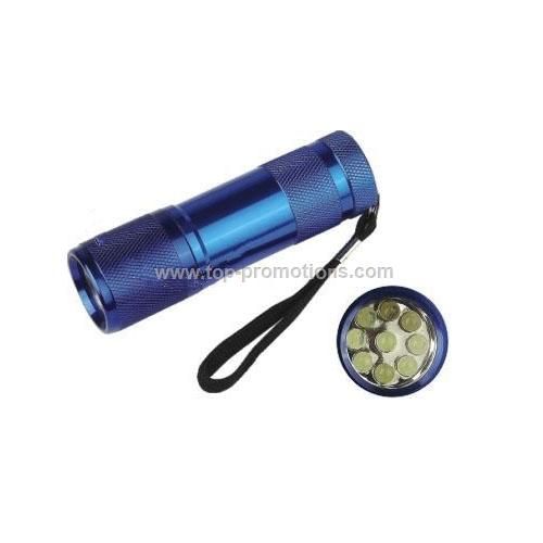
1 ea. Dollar store type flashlight. (needed only for the LED PC board)
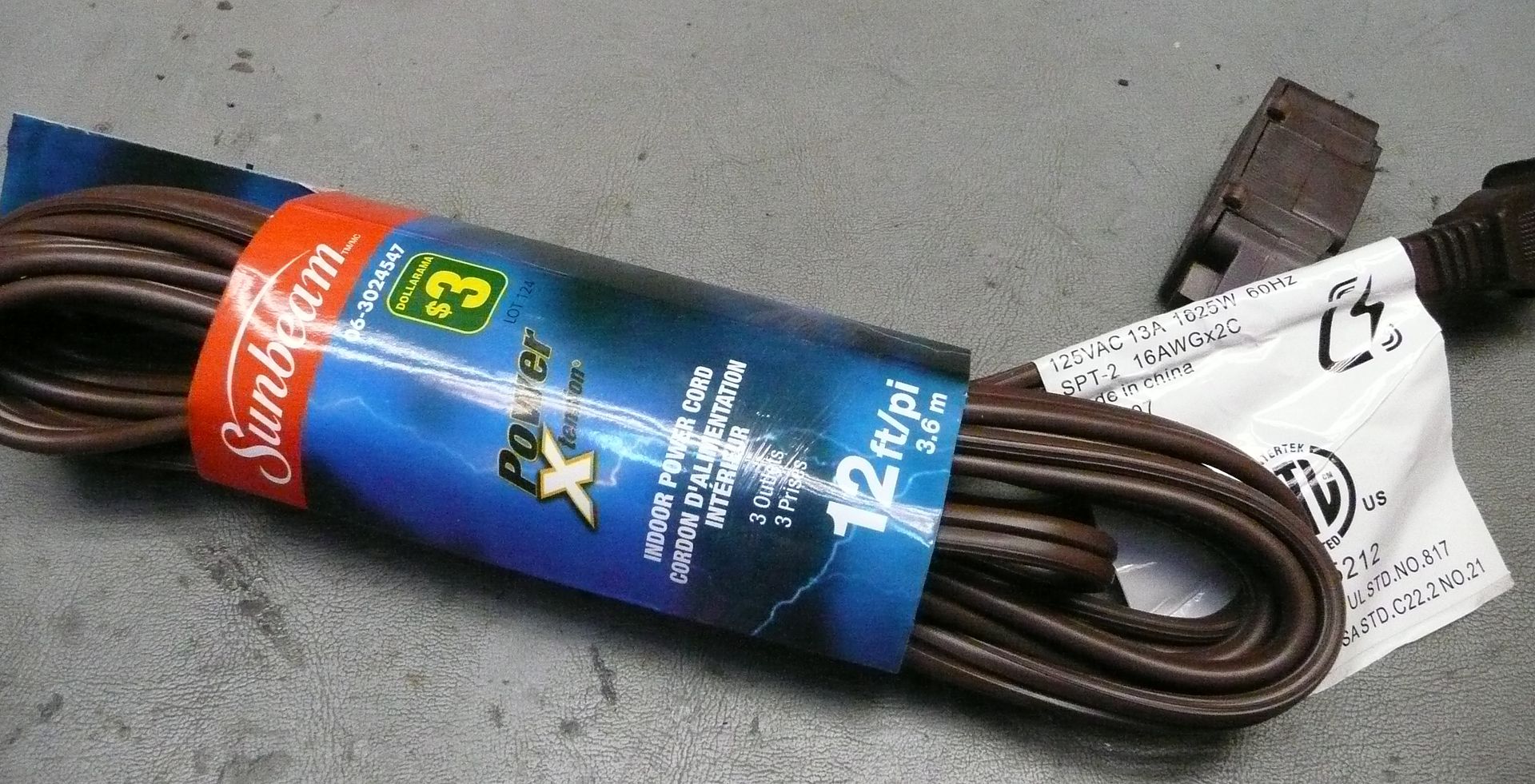
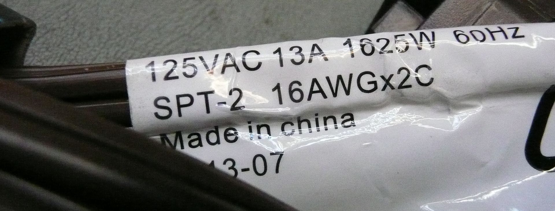
1 ea. Dollar store 12' AWG 16 extension cord.
Crimp type cable connectors.
An old 3 prog power cord. Just need the wall plug with a few feet of cord.
*******IMPORTANT SAFETY NOTE"*******
The supply linked above is rated at 40 amp! This means if shorted the cord willl get red hot before breaker will cut in. The installation of a 15 - 20 amp fuse or breaker is HIGHLY recommended.
Safer supplies are available: (little more money and encloses recommended but will shut off at 15 amp.)
Any will work. Pay attention to the size as you will want to find an enclosure to fit it best.
$31.95 L6.9" X W2.4" X H1.1"
$32.95 L7" X W3.9" X H1.3"
$31.95" L6.26" X W3.8" X 2H1.18"
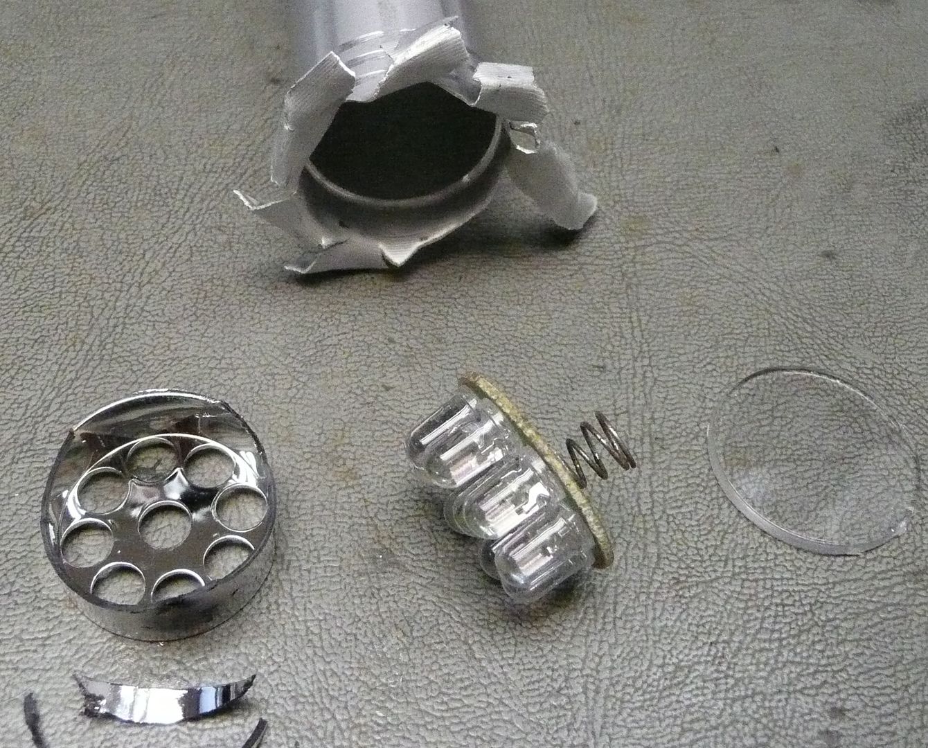
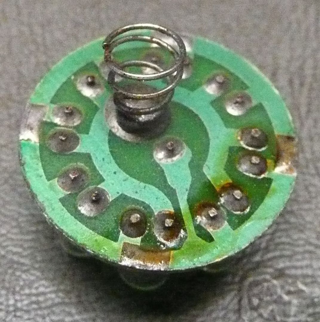
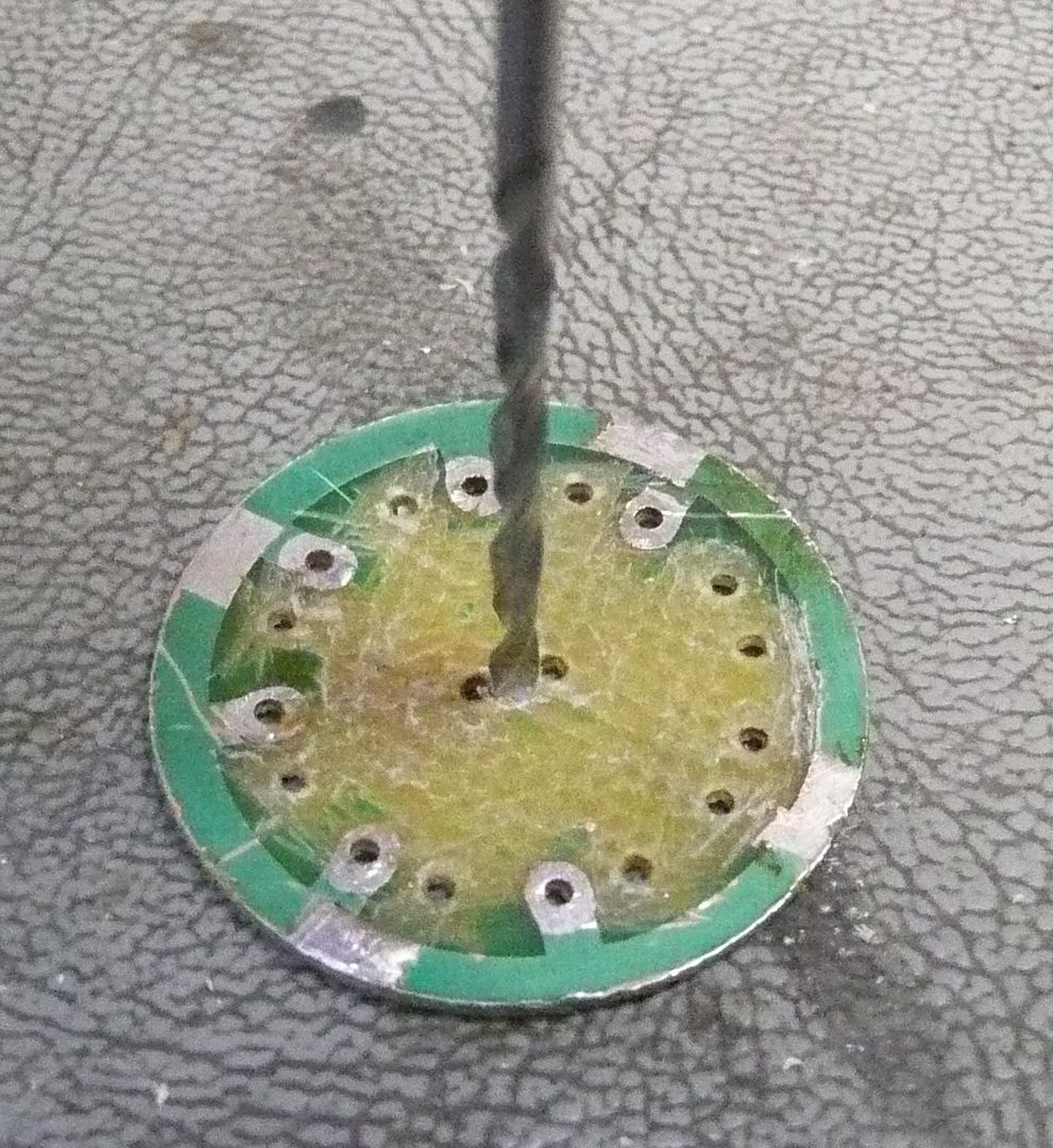
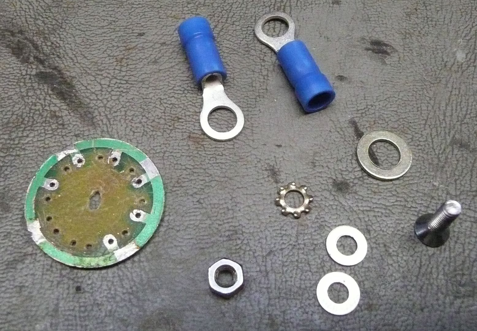
Ok, first thing is to prepare the board which comes inside the flashlight.
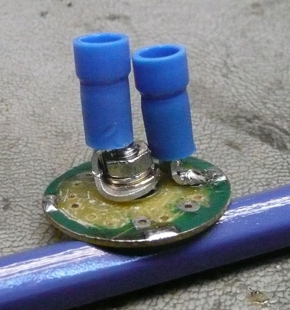
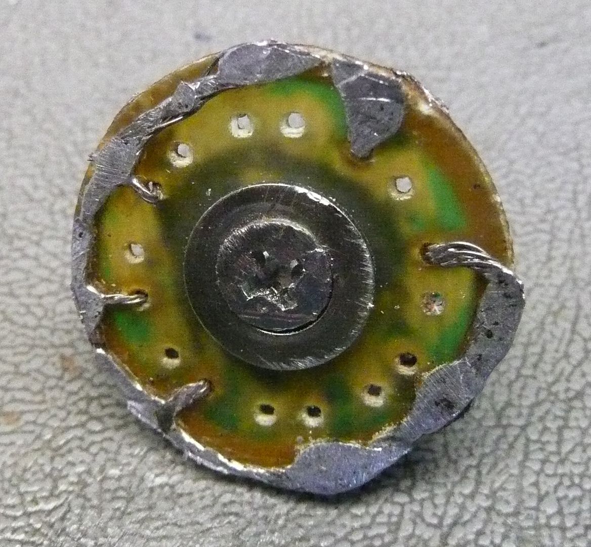
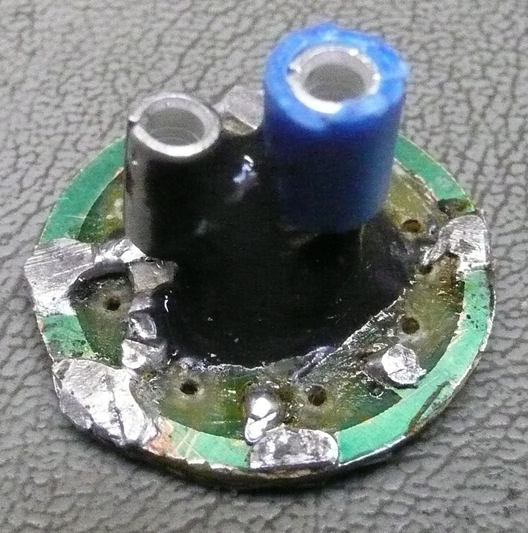
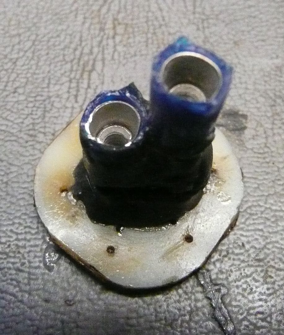
I have made a couple now as I have colleges which twisted my arm. The second unit I made ended up a little different as I opted to mount the connector a little different to center the wires better. It also only makes ground connection on the top side rather then both sides. The black stuff is my friend Mr. JB Kwikweld, he holds it all securely together as a single piece.
Next it to prepare the extension cord.
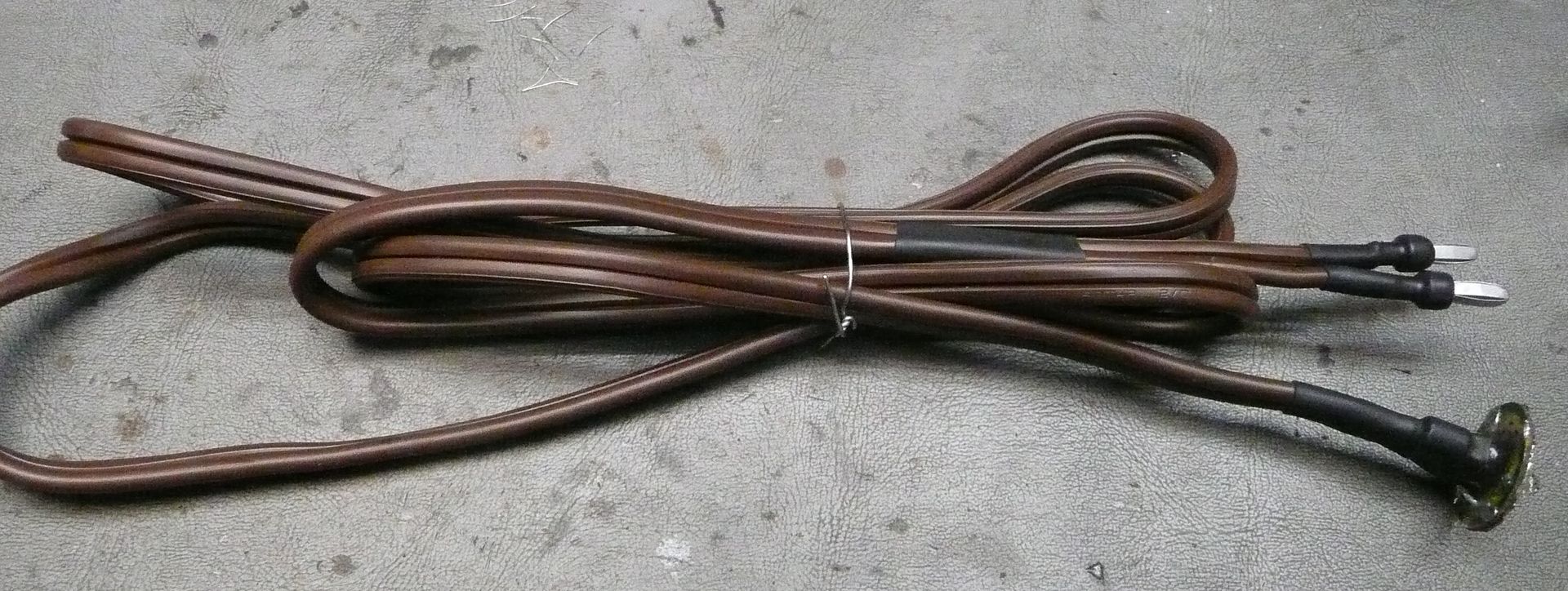
It is VERY important to use AWG 16. Cut it 6' long. The gauge and length is extremely important as that is the needed resistance to drop the 5 volt supply down the the rated voltage being used by the FV device.
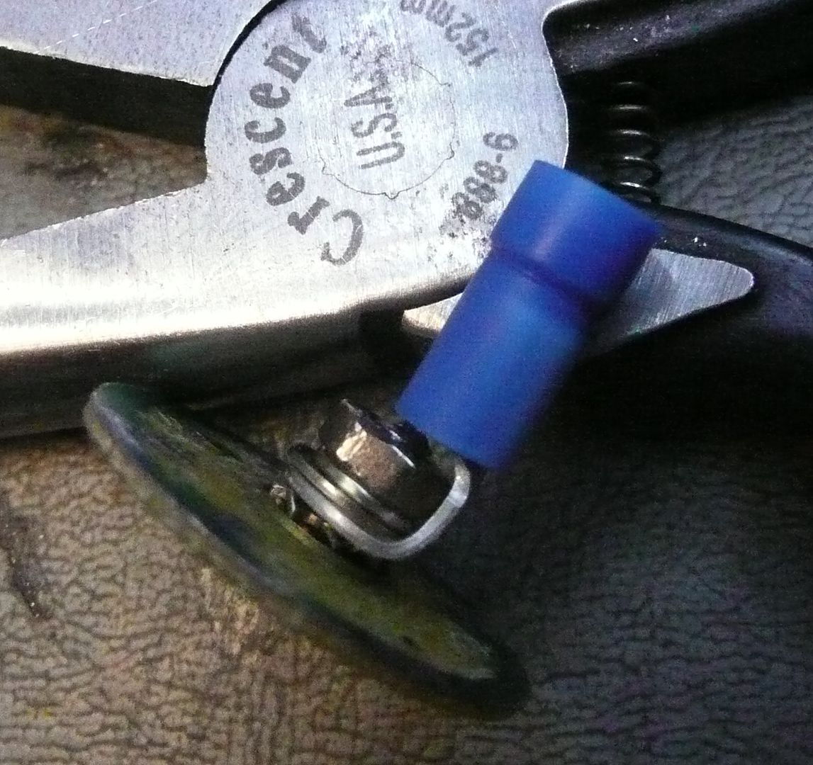
Now prepare the wire ends and connector ends and solder together such that it is very secure. The end that goes to the supply can just be the wire stripped and tinned with the solder. However I opted to use banana connectors so it can be unplugged.
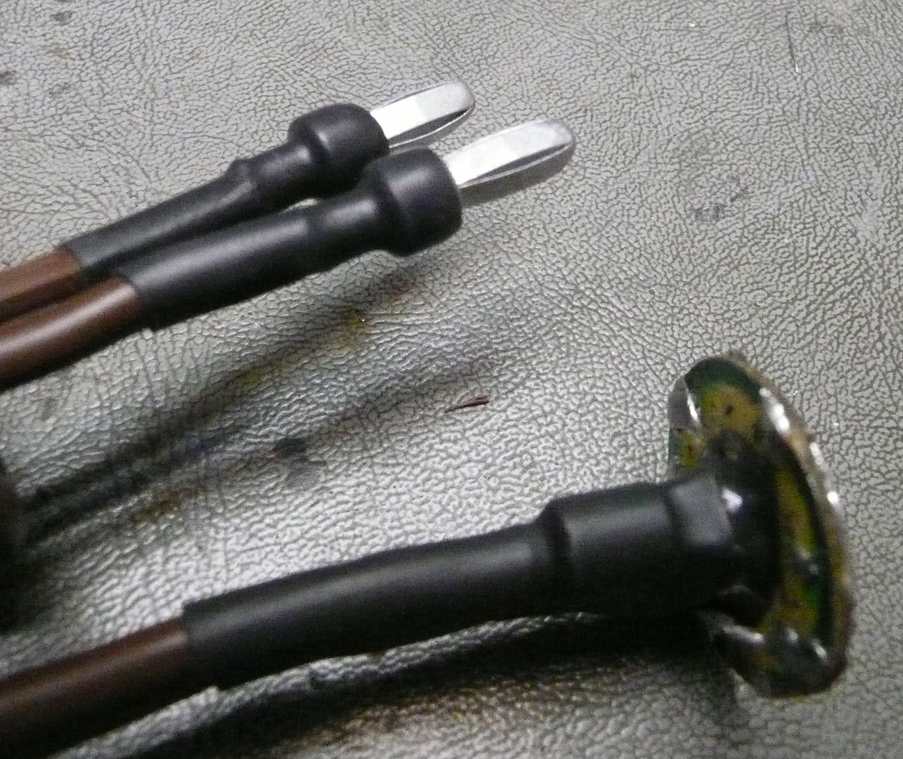
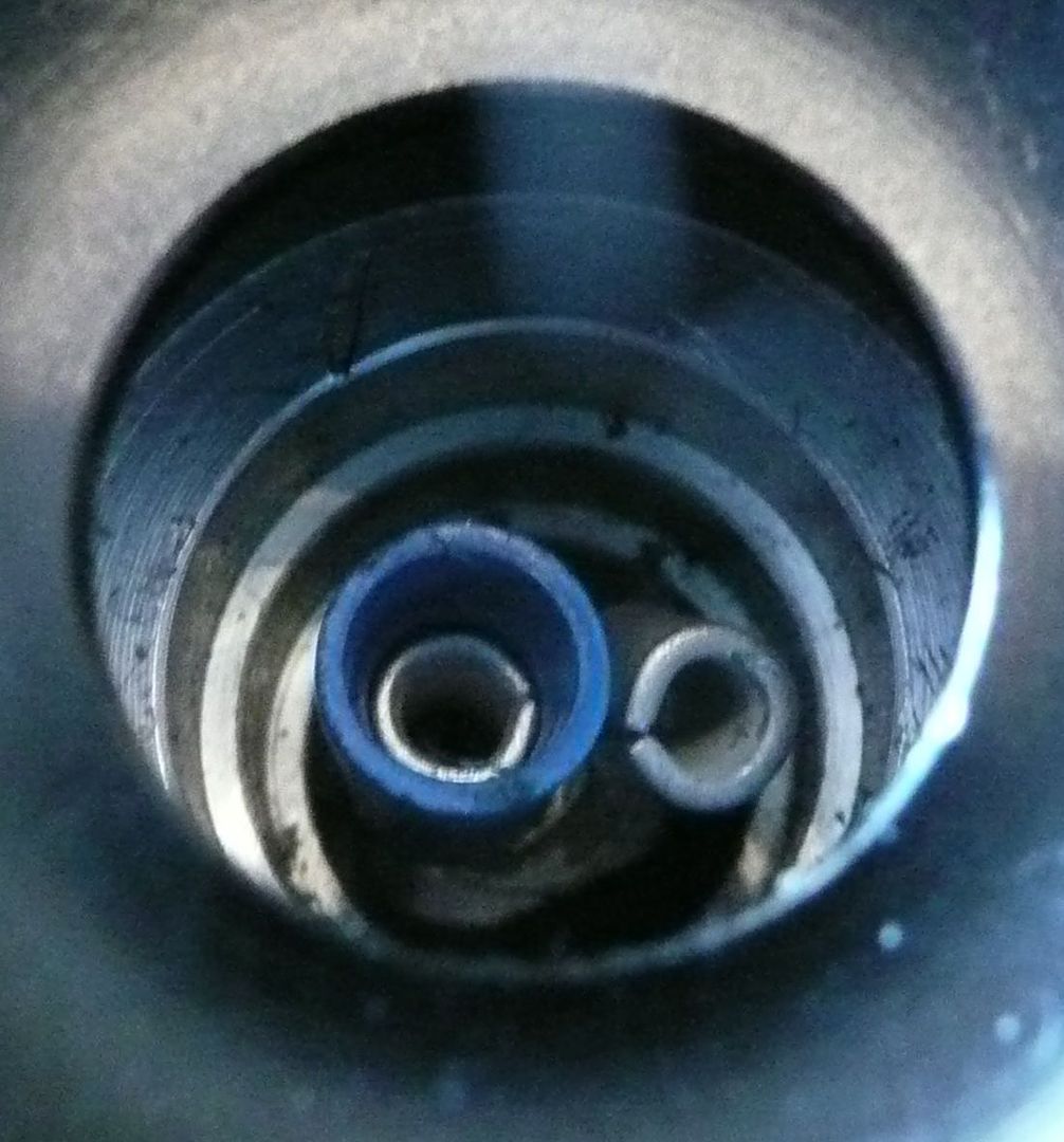
At this point you have all it takes to get PAing. Undo the FV at the point just below the button switch and feed the wire down through it. The disk end will sit on top and when screwed back together it will complete the circuit to the top portion of the FV. The cord will be hanging out the bottom and is actually usable without any further modding of the FV. Use your own judgement on how to take care of the wire coming out. Could be as easy as drilling a hole in the tube or remove the bottom switch. I did the latter and made a spacer to feed the wire through. Talk more on this later.
The making a hole in the mid section would likely be the best option for those who want to switch between portable mode and home vape mode. (No longer my intent.) I'd place the hole closer to the top so that feeding the cord through would be a little easier. Maybe a spot that sits comfortably between your figures while holding.? But low enough to not stress the connections. Also would solve the making a stand issue.
The open end of the wire is connected to the 5 volt power supply. Wire up the AC to the supply and you're ready to go. The supply has an adjustment of +/- and usually comes centered for 5 volt. While observing the heating element, slowly adjust this for you're preferred heater glow. This voltage control should give the desired heat range. If the unit is not sitting in a range you like the course adjustment is the cord length you use. I found 5 1/2 to 6 feet hits the spot nicely. The shorter the hotter.
"Option" for supply with no +/- adjustment:
It is also possible to substitute a non adjustable supply such as a PC supply (75 watt or better) but would have to do a one time adjustment. The adjustment will be in the wire length. Start with 6 ' or more and see what the glow is like. With this, "mine" would be too faint for use. Just starting to think about glowing.? Units will likely vary pending other variables. Shorten the cord 2 " at a time and repeat testing. If no glow by say 5 1/2 ' I'd think there is a contact problem somewhere. Or your unit never did get that hot to start with? 5 ' would be the shortest to try because this would indicate something wrong for sure. And once fixed the heat will be too high. Best to get a supply with some variability. Then again most folks can find this type of supply to get going till that one from China comes in after a month or more.
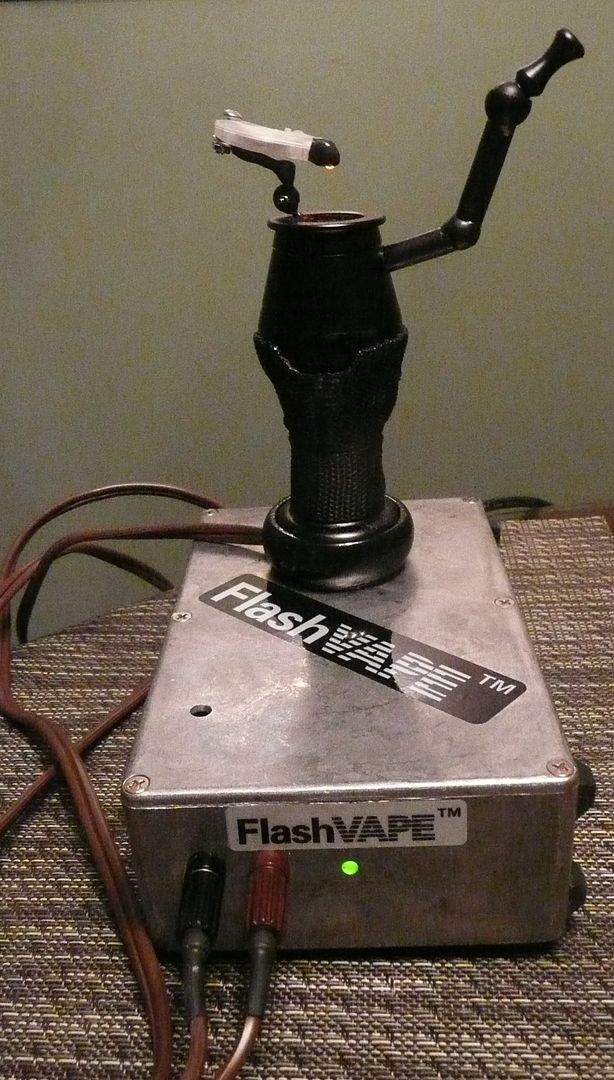
I also found a metal box to put mine in. Still haven't gotten around to installing a switch and a couple vent holes but will down the road. The supply I am using is not the one I linked to as I found elsewhere. It is 95% efficient so venting is not mandatory for it. The one in the link above is not as efficient and definitely needs venting. It even has a fan but then again the case that comes with it is not too bad and another case is not as critical.
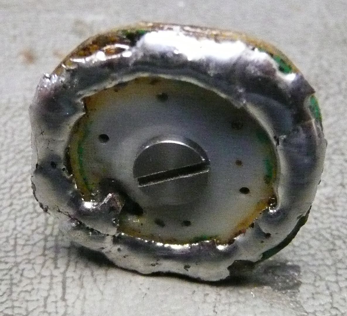
If you are fortunate enough to have the older thread type base, it will thread on in place of the center tube to make a "stubby FV".
Either way, the bottom switch can be removed so the wire can come out from the bottom. A spacer can be made so the wire comes out the side. I made a fancy guy but much could be done with some packing and electrical tape. Mine is made from JB Weld putty. (of course)
Have fun and play safe.
Oh, one last thing.....sit back and ....
This is a DIY which only requires some crude soldering skills. The total cost to create a working FVPA will be under $25.
The difference between this supply and the PA made by FV is the way it is regulated. The OEM unit is regulated to the 3 - 4 volts and the supply wire is zero ohm wire which is quite expensive and is a little short to keep the resistance as low as possible.
The way this method works is to actually count on losses in the wire to knock down the 4.6 - 5.4 volts to the desired 3 - 4 volts. The heater resistance of the FV is .3 - .4 ohms and we need to dump about 1/5 of the voltage, we need approximately .1 ohm in series. This is where the AWG 16 lamp cord type wire comes in. 5 1/2 to 6 feet of this wire equals this resistance. The wire gets slightly warm as it eats up 1/5 of the power of the FV and dissipates as heat.
The required parts are:
1 ea. Power Supply 5 volt with minimum 14 amp output. $17.50 here. (Also see alternate below to get going right away.)
1 ea. Dollar store type flashlight. (needed only for the LED PC board)
1 ea. Dollar store 12' AWG 16 extension cord.
Crimp type cable connectors.
An old 3 prog power cord. Just need the wall plug with a few feet of cord.
*******IMPORTANT SAFETY NOTE"*******
The supply linked above is rated at 40 amp! This means if shorted the cord willl get red hot before breaker will cut in. The installation of a 15 - 20 amp fuse or breaker is HIGHLY recommended.
Safer supplies are available: (little more money and encloses recommended but will shut off at 15 amp.)
Any will work. Pay attention to the size as you will want to find an enclosure to fit it best.
$31.95 L6.9" X W2.4" X H1.1"
$32.95 L7" X W3.9" X H1.3"
$31.95" L6.26" X W3.8" X 2H1.18"
Ok, first thing is to prepare the board which comes inside the flashlight.
I have made a couple now as I have colleges which twisted my arm. The second unit I made ended up a little different as I opted to mount the connector a little different to center the wires better. It also only makes ground connection on the top side rather then both sides. The black stuff is my friend Mr. JB Kwikweld, he holds it all securely together as a single piece.
Next it to prepare the extension cord.
It is VERY important to use AWG 16. Cut it 6' long. The gauge and length is extremely important as that is the needed resistance to drop the 5 volt supply down the the rated voltage being used by the FV device.
Now prepare the wire ends and connector ends and solder together such that it is very secure. The end that goes to the supply can just be the wire stripped and tinned with the solder. However I opted to use banana connectors so it can be unplugged.
At this point you have all it takes to get PAing. Undo the FV at the point just below the button switch and feed the wire down through it. The disk end will sit on top and when screwed back together it will complete the circuit to the top portion of the FV. The cord will be hanging out the bottom and is actually usable without any further modding of the FV. Use your own judgement on how to take care of the wire coming out. Could be as easy as drilling a hole in the tube or remove the bottom switch. I did the latter and made a spacer to feed the wire through. Talk more on this later.
The making a hole in the mid section would likely be the best option for those who want to switch between portable mode and home vape mode. (No longer my intent.) I'd place the hole closer to the top so that feeding the cord through would be a little easier. Maybe a spot that sits comfortably between your figures while holding.? But low enough to not stress the connections. Also would solve the making a stand issue.
The open end of the wire is connected to the 5 volt power supply. Wire up the AC to the supply and you're ready to go. The supply has an adjustment of +/- and usually comes centered for 5 volt. While observing the heating element, slowly adjust this for you're preferred heater glow. This voltage control should give the desired heat range. If the unit is not sitting in a range you like the course adjustment is the cord length you use. I found 5 1/2 to 6 feet hits the spot nicely. The shorter the hotter.
"Option" for supply with no +/- adjustment:
It is also possible to substitute a non adjustable supply such as a PC supply (75 watt or better) but would have to do a one time adjustment. The adjustment will be in the wire length. Start with 6 ' or more and see what the glow is like. With this, "mine" would be too faint for use. Just starting to think about glowing.? Units will likely vary pending other variables. Shorten the cord 2 " at a time and repeat testing. If no glow by say 5 1/2 ' I'd think there is a contact problem somewhere. Or your unit never did get that hot to start with? 5 ' would be the shortest to try because this would indicate something wrong for sure. And once fixed the heat will be too high. Best to get a supply with some variability. Then again most folks can find this type of supply to get going till that one from China comes in after a month or more.
I also found a metal box to put mine in. Still haven't gotten around to installing a switch and a couple vent holes but will down the road. The supply I am using is not the one I linked to as I found elsewhere. It is 95% efficient so venting is not mandatory for it. The one in the link above is not as efficient and definitely needs venting. It even has a fan but then again the case that comes with it is not too bad and another case is not as critical.
If you are fortunate enough to have the older thread type base, it will thread on in place of the center tube to make a "stubby FV".
Either way, the bottom switch can be removed so the wire can come out from the bottom. A spacer can be made so the wire comes out the side. I made a fancy guy but much could be done with some packing and electrical tape. Mine is made from JB Weld putty. (of course)
Have fun and play safe.
Oh, one last thing.....sit back and ....
Last edited:


