VapCap Induction Heater for Desktop and in Car Use

Pipes

Addicted DIY Enthusiast
Accessory Maker
I'm afraid it's hit and miss. And all suppliers seem to get the bad stuff. Like I have said before, get extra FETs at the same time. Best you can do is look for a supplier which shows units with "QC PASSED" stickers affixed to the drivers. At least this should cut down on reversed diodes but can't say about FET quality.
I think for anyone to attempt this, they should have some basic soldering skills.
-Diode polarity should be first thing to check as will just blow the FETs upon first time power is applied.
-Soldering of work coil is "highly" recommended as it input power. A loose work coil will blow the FETs instantly.
Here's a post I did when I received a 100% bad batch.
Hey guys. Today was not a good day. A definite downside to the China business risk taking end of things. Also. a prime example of why I need to move away from those pre-made heater drivers.

So today I started to make up some IHs using drivers from a new batch I got lately. Actually, two orders of 50 each but today was to first time I started to use any. First unit just starts smoking right away. Figured it was just a bad driver as has happened before. Second unit, dame thing. Third... dido. After much head scratching and a little swearing, I found the problem.

They all have their diodes installed backwards. 100% of 100 units, assembled wrong from factory. :bang: All 4 diodes installed reversed. Supplier wants me to return with tracking at my expense. Or he will refund me a whole $50 for the lot. So guys, beware some sellers for these. If just buying singles, pick a seller that has a QC sticker on the boards. If you do get one with backwards diodes, the FETs will blow the first time you attempt to use it.


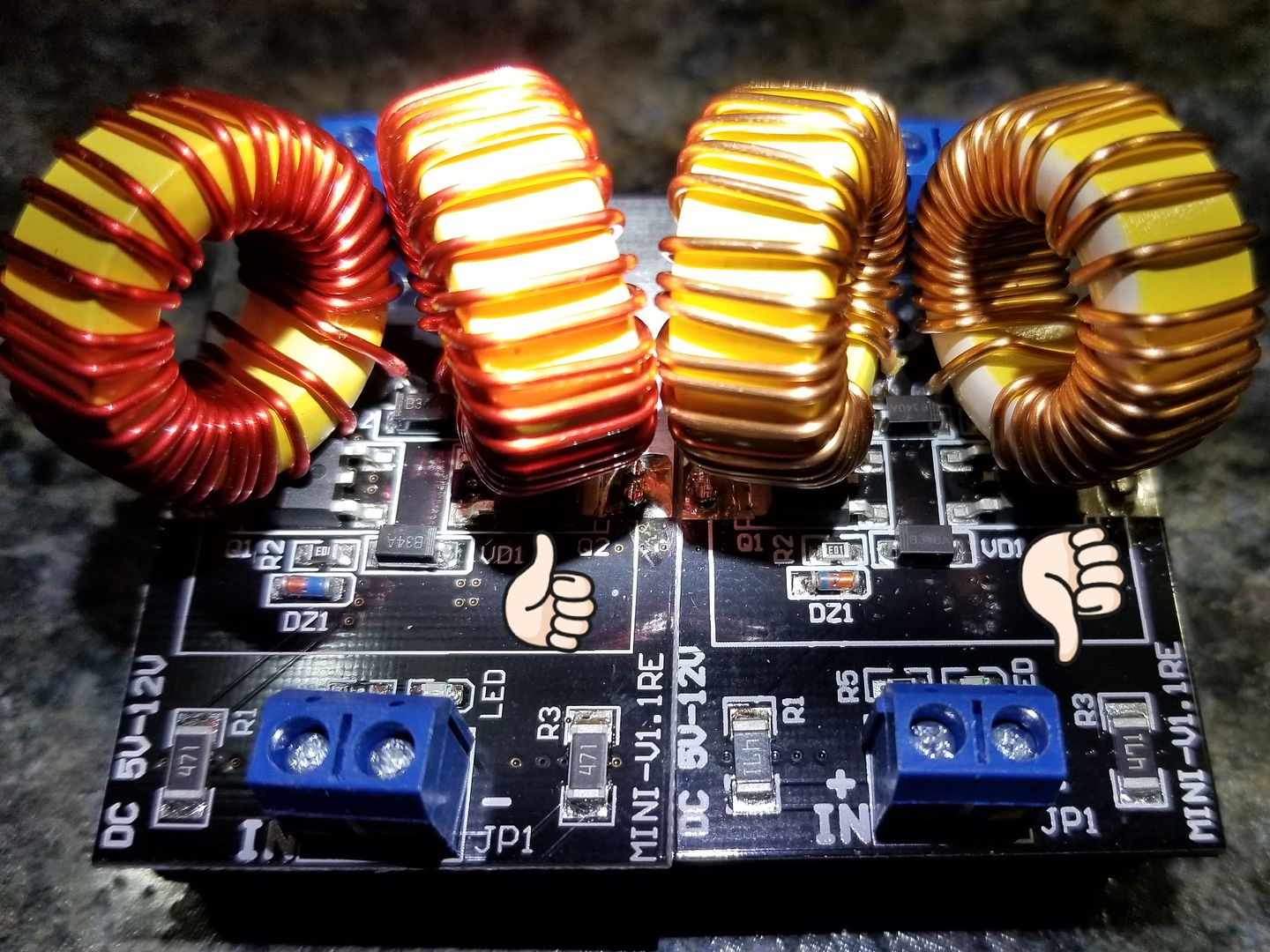
The unit on the left is a good unit and the one on the right is a bad unit. DZ1 and VD1 are backward.

Reworking is not a simple task. Need to unsolder one side of caps to get at the coil legs to unsolder as well. Then you have access to the two diodes hidden under the coils.
The DZ1&2 can just be removed and discarded, but the VD1&2 need to be removed, flipped and re-soldered.
Then clean up and resolder the coils and caps back in place.


So what does this mean? Not much for most folks, as it is my problem but will slow things down some. But I'll muddle through it. Just needed to rant some...:rant:

:smug:
Don't even pre-test anymore, just change the drivers out. Drivers going bad in the field has dropped to just a couple percent now since I started to change them out late last year. Was closer to 15-20% at one point before that.

I wonder if someone has try to run the zvs with a 7,4 lipo battery...The zvs is rated at 5V-12V so...it should work some way...and would a 7,4 lipo with a high amps like 2200 mah and high discharge something like 40C work like a 11,1V and 800 mah 20C lipo?

Thanks for reading
You are pushing the spec here. The closer you get to the lower side, the higher the risk of getting lock ups and no oscillation. Which results in.... yepper, blown FETs. Likely work OK while battery is full but once it starts to drop off, the risk increases. Don't forget that there will be voltage loses in the wiring, switching, etc. which will lower the source voltage some. I'd advise to stay at a safer operating voltage range.
@rz was working on a 2 cell driver and found he had to add a voltage booster circuit to supply the gate voltage to get it to oscillate reliably.
:science:
 
Last edited by a moderator:

nachooo

Well-Known Member
You are pushing the spec here. The closer you get to the lower side, the higher the risk of getting lock ups and no oscillation. Which results in.... yepper, blown FETs. Likely work OK while battery is full but once it starts to drop off, the risk increases. Don't forget that there will be voltage loses in the wiring, switching, etc. which will lower the source voltage some. I'd advise to stay at a safer operating voltage range.
@rz was working on a 2 cell driver and found he had to add a voltage booster circuit to supply the gate voltage to get it to oscillate reliably.
:science:
Your mention of a voltaje booster has make me think….Well in my search of portability...a 1 lipo cell 3,7 V..and a booster… But I think the booster Will need to support lot of watts...and probably the booster plus the battery will need more space than a 11,1V lipo...
 
nachooo,

Pipes

Addicted DIY Enthusiast
Accessory Maker
The booster was for driving the gates only. Low power. The main drive voltage isn't as important for it to oscillate.
Not really feasible to boost the drive voltage as would be a much bigger undertaking.
Getting into ecig mod power stuff now which is not a pure DC but rather pulsating DC and wattage is determined by duty cycle. Good for driving a heating element but not good for supplying an oscillating type circuit.
If you really want play play, there are other ways to cut down the size. :science:
You can ditch those big ass coils and replace with these guys and eliminate one of the capacitors all together. You can mount both these coils where the capacitor is removed from. This will cause the unit to oscillate at a much lower frequency but still work very well. I have done this in my experiments with very good results. :science:
Now you have room for the 3S cell in your design...?
 

asdf420

Well-Known Member
Got new batteries. It's aliiive! I'm using it while it's charging now, some minutes after the charger stopped buzzing noticeably.
 
Last edited:
asdf420,
  • Like
Reactions: cybrguy

nachooo

Well-Known Member
The booster was for driving the gates only. Low power. The main drive voltage isn't as important for it to oscillate.
Not really feasible to boost the drive voltage as would be a much bigger undertaking.
Getting into ecig mod power stuff now which is not a pure DC but rather pulsating DC and wattage is determined by duty cycle. Good for driving a heating element but not good for supplying an oscillating type circuit.
If you really want play play, there are other ways to cut down the size. :science:
You can ditch those big ass coils and replace with these guys and eliminate one of the capacitors all together. You can mount both these coils where the capacitor is removed from. This will cause the unit to oscillate at a much lower frequency but still work very well. I have done this in my experiments with very good results. :science:
Now you have room for the 3S cell in your design...?
After your post I think I am gonna buy a soldering station… Thank you very much for the info...

After changing these coils… and remove one capacitor (I guess it doesnt matter one or another), should I have to make other changes? Like reduce the number of turns in the big coil (the one that gives heat) or other changes?. Sorry about my english…
Thanks again

A very much reduction in size… 5,5 cm x 3,5cm x 4 cm would become a 5,5 cm x 3,5 cm x 1,5 cm...It worth the while...
 
Last edited by a moderator:

Pipes

Addicted DIY Enthusiast
Accessory Maker
Nope, keep the work coil the same. I turn around dowelling to reduce the diameter. Turns works out to about 11 loops after reduction.
 

rz

Well-Known Member
@nachooo the circuit does work with 2S, however like @Pipes mentioned I use a boost converter to increase gate drive voltage to a predictable ~12V, even while pack voltage drops to about 5V where the BMS cuts it out. I found some MOSFETS that only needed about 6V to start oscillating, and most wouldn't even start at 5. I fried a fair amount of MOSFETs during testing and often it seemed random but there are many reasons a MOSFET can die. I'm sure there are MOSFETS that can work reliably at this voltage range. I'm still experimenting and hope to find some.

Once I kept the gate voltage higher, I found that most suitable MOSFETs behaved really well and oscillated down to 4V supply (which I'd never run them at anyway). I've had rock solid reliability in this way as long as I keep the MOSFETS cool! Keep in mind that the supply currents are about doubled to get similar performance, while the power losses are more likely squared. By modifying the work cap and coil you can reduce the frequency which reduces the total current and delivered power too. This also helps reduce switching losses in the MOSFETs. I find the undesired heat produced from a 60W 2S setup to be quiet a bit more than from a 60W 3S setup. If you manage all these things it can work, and work well, but if you can avoid it, go with 3S. I mainly followed the 2S route cause I wanted to use 18650 cells in a somewhat compact form and I enjoyed pursuing it. I wouldn't necessarily stay 2S on other IH designs I work on.

I could see some advantage to boosting the main supply voltage (not just the gate voltage) from, say, a 3S setup to a consistent say 13V. Firstly, the performance would be a lot more predictable. IH power transfer changes as the battery voltage drops. While it may take 5 seconds to click from cold on a full charge, it may be 8~10 seconds on the bottom end of the battery cycle. A balance needs to be found for optimal performance. when heat up is too fast, you're more likely to over-shoot and char a shot, and there isn't enough time for heat to spread into the whole tip. Slowing it down too much may mean it's just too slow half way through the charge cycle and well that doesnt help either. the 5~8 second range for first click seems to be a good target for a charge cycle, and you learn to pace yourself accordingly (specially if you are surfing above the click-line). Boosting the supply voltage to a constant and tuning the IH accordingly could give you a more consistent 8 seconds (for example) through the range. There would be some losses in in the boost circuit, but it may be offset to some degree by fewer losses in the IH running at a more suitable voltage. There would also be the complexity of using a suitable boost circuit that's up to the task and it's additional cost. I wouldn't be surprised if a properly designed system would perform really well though I think a 3S system with some power monitoring and PWM would be a suitable route to stabilize performance over the charge cycle.

Dropping down to a 1S doesn't make sense for this current hungry circuit. You would need to boost everything, and would be plagued by too many losses and unnecessary complexity.


either way keep us updated! :D
 

Prophecy

Well-Known Member
Hello!

I'm a quiet long-term reader here in the Vapcap thread since a while and a big fan of the vapcap was also my first vaporizer (the M) than i have buyt in sebtember last year 3 months later I upgraded to the omny xl.

My skeletor induction heater arrived today and I'm very happy with my new tool and big thanks to @Pipes for his work, so i spent today time to make my enclosure fit for the skelly and here are the results.

I still have a question how have you attached battery level indicator? I've tried with super glue that does not really hold on the metal any other ideas?

Thanks a lot!

EDIT: After the second try the battery level indicator keeps on his place :)


Last edited:
Hello, tried looking through the thread but saw a lot more on this with regards to battery-based systems and I was wondering, is this is a correct diagram for how to wire a desktop system just using a 12V 6A power supply?

XOw7hUO.png
 
MetroidsAteMyStash,

Dynalowrider

Well-Known Member
PM, Pipes on here. He is in Can. He will put you on the list and notify you, when ready. Welcome to FC. Doc
 
Dynalowrider,

cybrguy

Putin is a War Criminal
Thank you @cybrguy I'm hoping to put together a couple more ideas around some barebones parts.
I meant to ask you if this was battery or plugin. You said you started with a Skelly so I'm guessing battery, but given it's size and shape I think it would be great as a plugin too.
Actually, looking at the vid it looks like it is plugged in with a PS behind it. That makes the most sense to me given it's shape and material. As much as I love my Trump head in a jar, I would swap it for this in a second. (No offense Pipes...)
 
Top Bottom