VapCap DIY Induction Heating : Bits 'n' pieces

TommyDee

Vaporitor
Maybe not quite up for the task. Looking for a smaller form factor cap.

The PCB is for the FET control circuit. I've completely isolated the caps and the ferrit'd coils from the PCB. The only connections to the PCB is the 3 lead-wires from the hard-wired sub-assembly using the 14 gauge 'hooks'. I could trim away a good 3/4" away from the PCB to save space without changing the function.
 
TommyDee,
  • Like
Reactions: lookhigh

TommyDee

Vaporitor
Caps add parallel but smaller typically suffers from more volume due to packaging. Since I am limiting power, I can reduce the size. I am aiming for 2/3 power level so a single 0.47 uf cap is about right. I also looked up some coils. These too come in different values. I got some insight but this too needs resolution. 33uh/47uh/66uh/100uh/220uh - 3a 5a, and 8a.
 

TommyDee

Vaporitor
I finally settled on a charging system for the battery pack.
I have a 12V charger that puts out a few amps. WallWart style.
I looked at regulated supplies; I fried a low output 12.6 volt supply; & it was all dumb. :suspicious:

This is for the 3x 18650 pack that is fitted with the 20 amp battery management system. I don't know exactly what this BMS does but at minimum, it switches the mains on the minus side [negative]. I also know it is direct voltage to each cell with whatever limits they can provide. I don't know if they have over-voltage or under-voltage protection or anything else only in that I wouldn't count on them anyway. I do know that the cells are treated through individual circuits and that means each cell is looked at and charged as if it were an individual power source. This is the bare minimum I expected.

I wanted to just plug in a 12.6 volt supply but the charge rate was nearing 2 amps on cells that were not even that far depleted so direct wasn't going to work. I reduced the supply output and the current went down, but the wall wart died within 15 minutes. So I scratched my head for a while.

I now have a 'trickle charge' solution. I wandered upon a 5 ohm 5 watt wire wound resistor. Turns out depleted cells [3 volts under load] would charge with a 12 volt supply at 300ma/hour charge rate. That is a very gentle charge current. The resistor is also barely warm to the touch dissipating ~1/2 a watt.

Why 12 volts not 12.6 volts? Easy, I have a nice 12V wall wart from the Launch Box Power Adapter which is quite capable. But furthermore, for Li-Ion cells, this is perfectly good for a mostly full charge since I will plug it in overnight anyway. There is 3 days worth of charge in those cells. And therefore I say that this is my experience with 12V and a 5 ohm resistor. 12.6 volts will work just as well and the current will go up some and the resistor will heat some more, but this is a viable charger for a 3S 18650 with a BMS incorporated.

Don't go over on the wall wart! 12.6! Strictly! That is the warning on the 20A BMS. This is because the BMS simply divides the input voltage. As Li-ion cells charge, their current drops which means less drop across the resistor. Essentially, Li-ion is balancing itself with the wall wart divided by 3 until there is no current drawn [ideally]. Therefore I feel more than confident that a 12 volt source will never over-charge a cell save a failure within the BMS circuit.

This little resistor charger is an old NiCad trick for novice racers. They use to plug NiCads straight into the wall with a single resistor between racing and calamity.

I did go an find the specifications on the 20A BMS - here at Banggood
 
Last edited:

TommyDee

Vaporitor
The balance chargers tend to have parasitic drain that is never good if a pack gets neglected.
Otherwise I am not sure what it brings to the party.

I was looking at charging options for 2x 14500. You can bypass the BMS for power delivery and only engage the charger. The charger circuit is the same on most of them. That way you don't have to worry about the power circuit, or interrupting it.
 
TommyDee,

PKOK

Well-Known Member
I've yet to build a battery version so for my next project... I know I'll have 3 18650's is series, all tacked together and crammed into a tiny box, so they won't be coming out to my normal charger. Charging Options as I know them are- a BMS, a Power Regulator or a Charging Balancing Board.
I have a bad habit of ordering parts not knowing diddly , I've these two coming
https://www.banggood.com/3S-18650-L...p-1454375.html?rmmds=myorder&cur_warehouse=CN

https://www.banggood.com/3S-20A-Li-ion-Lithium-Battery-18650-Charger-PCB-BMS-Protection-Board-12_6V-Cell-p-1118043.html?rmmds=myorder&cur_warehouse=CN

I'll have to reread your stuff to get some good ideas :hmm:

 
PKOK,

TommyDee

Vaporitor
No need to get too lost in past words so it is easier to just work together. The first link is what I was suggesting - just a balance charge circuit. That's all that is needed to manage cells in a pack. That is how LiPo RC packs work (which also makes a great option). I think that is what the PSM did.

The second link, although not working, is the one I put in my 3S 18650 pack. I am using the full function of letting the BMS also protect against over-discharge or short circuit. These boards break the negative pole if things go wrong. This is useful to know when setting up a system. Implementing this circuit where the battery pack can disconnect completely past the BMS is a good idea when you have no other way to disconnect them quickly in case of a thermal event.

That 20A board has been working very well on the hot IH. Days of charge. And now it has a simple trickle charger to 'keep it topped off'. I haven't found a specification yet for maximum charge current through these boards. I'm assuming 1/2 amp is reasonable and will keep things cool.

I did learn this morning that balancing circuits basically disconnect an individual cell's circuit when 4.2 volts is reached until they are all at the same state. I still don't know why they have several distinctions with regard to the 3 different offerings. Just haven't found the right reference to kick-start a comprehensive understanding of the circuit and options. Certainly not for a lack of trying.

I buy a lot of board from China just to have them on hand.

Will you be doing the line-level switch or the FET switch?
 
TommyDee,

PKOK

Well-Known Member
Sounds great TD thanks, so you're suggesting I use just the Balancing Board? What about the protections
the BMS brings? Low voltage ⚡ comes to mind. Line-level I'm not familiar with unless it's in a boat :) tell me about it. Where I'm getting lost is how I bring mains power in for charging unless I use a Power Regulator with the Balancing Board.
So if the 20A BMS has been working for you why the departure.
On a 3s board, can you add another 3 batteries in parallel? Just thinking about a long day out, like camping.
Wouldn't a Power Regulator have helped with your problem on your previous post #154?
I know I've got a LM2596 from a previous China grab. Much better ones exist.
I assume 12-12.6v is the charging voltage but amperage ? 1-2A?
I've lots of stupid questions, bear with me, I'll get up to speed....maybe
Oh! here's another, couldn't you use the Bal Board with a protection board with no charging circuit like this one https://www.banggood.com/Seiko-Protection-IC-10A-Protection-Board-For-3S-11_1V-12V-12_6V-18650-Lipo-Battery-p-1107660.html?rmmds=detail-left-hotproducts__7&cur_warehouse=CN

or the previous one we spoke of even better.
 
Last edited:
PKOK,

TommyDee

Vaporitor
Maybe I should elaborate on my case for a balance charger first - I need a dockable 2S solution and this is perfect for just a charger on a stationary charging dock.

Your project, indeed, use the 20A board. Route through the FETs as intended. That is how I set up the pack in the previous pages. This will take care of 95% of your safety concerns.

The charger comes in on the output of the BMS. That is why you shouldn't use a device while a charger is plugged in -unless- it is rated for the load. Voltage to the cells is divided 3 ways so the output needs to be 12.6V or less. If the source is not stable then yes, you need a regulator in front of the battery pack/BMS for the charge system. Again, things are muddy here but it is a stern warning. Technically there is a voltage limiter in the regulators that control this process. However, the circuit is not very robust so without confirmation, I wouldn't charge over a 1/2 amp rate.

LM2596 is a great regulator used in CV|CC mode. I even have a few. I voided two issues in my setup - undue heat and headroom. Undue heat because the LM2596 circuits are handling 6 watts. Without some level of cooling effort, I don't like its odds... or the odds of whatever it sits on. I am also not impressed by their stability unless you do some active limiting to the range of the trimpot for voltage. If you can get a circuit under control and into a box with some cooling and a heatsink, you got a decent charger.

I have a 99c wall wart that puts out 12.45v and can't put out more than an amp. The 5W resistor is overkill to manage heat. The charge rate is 0.3 amps. I'm $2 into a charger that fails open circuit and protected from short circuit or over-voltage through the BMS. I'm covered! Walk inside the house and plug it in like I do my phone - charge overnight. The BMS is my 3rd level of protection. I am line isolated by a UL approved technique on the wallwart end. But this is also me cheaping out. But not without serious consideration of the ramifications. I am a lot more exposed with exposed battery terminals. And on headroom - I have a 12V/10A supply that I can crank up to 12.6 but I need much more to get stable regulation, 13.8v preferred.

There are choices. They all mean something. I want to narrow down to your desired requirements.

As to mains... terminology has really drifted over time on a lot of things so you can locally follow my meaning. DC- is what is switched in the BMS. DC+ just passes through. Output is the input for the charge circuit. Again, it is not recommended operating the the battery pack while charging.

...physical switch or a FET switch?

For posterity - That's negative on this end for all cells in the holder.
See how negative goes into the BMS and comes out the other end next to the red wire? That is the full current from the load going through the FETs. We use 5-8 amps so these may get warm.

49571401931_c6438a344f_h.jpg
 
Last edited:
TommyDee,

PKOK

Well-Known Member
Ok so let's assume I'm using the 20amp board, is there a charging circuit on that board?, would it be possible to add the Balance card as well?

If the source is not stable then yes, you need a regulator in front of the battery pack/BMS for the charge system. Again, things are muddy here but it is a stern warning. Technically there is a voltage limiter in the regulators that control this process. However, the circuit is not very robust so without confirmation, I wouldn't charge over a 1/2 amp rate.

So I'd only need the regulator if I were to charge off solar when camping or similar. I may have mentioned that I was in Mechanical Design the closest I came to Electrical was in Packaging, oh in the late 70s I wrote shop instructions for wire harnesses.

Sorry off-topic, The Regulator, it seems to me that it would be an advantage, couldn't it standalone by controlling the voltage/amperage to the battery? Once it hits
4.2 volts assuming that is the set on the Reg the batteries should be ok left plugged in. Dang I just found a video supporting that theory, what do you think?
I'm not saying this is the route I'd like to take, just throwing ideas around.

There are choices. They all mean something. I want to narrow down to your desired requirements.

TD I'm not set in stone for this battery version but if I prioritize:
1) I'd like it to have very good battery life even at the cost of size. Although I'd like to build another
hand held similar to yours :)
2) Not absolutely necessary but It would be nice to be able to charge solar when camping or just because!
Otherwise, this is a learning exercise for me & it's fun!
 
PKOK,
  • Like
Reactions: TommyDee

TommyDee

Vaporitor
Your requirements are right up my alley. Balance board v. 20A board - the 20A board incorporates the same circuit as the balance board. It just adds a high current FET switch. You could disable the 20A onboard balance circuit and use an external balance board, yes. That gives you onboard protection for the high current and the option to remote the balance board. However, putting the balance board with the battery pack seems redundant.

The beauty of the BMS and the balance charger is that you can give it any DC voltage up to 12.6V. There is a regulator on-board that should cut the output to each cell at 4.2V. But if the string has more than 12.6V input, there is nothing that keeps the cells from dividing whatever voltage it's given except the FET switch on the BMS. So if the solar array puts out 12.6V or less (11v min), you can charge directly. If it puts out more, then yes, you need a regulator. CV/CC set to 1/2 amp and 12.6V will work great. Bottom line, you are protecting the battery pack against over-voltage.

Your choice of 3x 18650 will certainly give you runtime.
 
TommyDee,

PKOK

Well-Known Member
Nah my camping array is a foldout, 3usb outputs at 5v/2.4amp MAX. Ok the USB output from solar, I can wire to the same male plug as the all wart or will I need a USB Input?

Your choice of 3x 18650 will certainly give you runtime.

Assuming I have the room, if I were to parallel another 3 would that double runtime?

TommyDee I appreciate you taking the time to fill in my blanks, very kind. I'm getting my MJ License
within a week or so & I'm pretty excited about that. The products they have available today is...
well interesting :)
 
PKOK,

TommyDee

Vaporitor
That array pushed to 12v will output 1 amp minus whatever inefficiencies are within the converter.
Again, be careful with those converters. They tend to be highly sensitive due to their wide range.

Paralleling the cells will double your runtime, yes.

Congrats on the license. It is indeed a new dawn. One that's way overdue.

I really like DIY efforts shared on forums. This is a great way to learn and get ideas as well.

Okay two questions
1) how do you want to activate your IH?
2) will it be an IH corded to the power pack or a one piece unit?

--------------------------------
edit: that converter you chose is a boost converter right? Most of the LM2596 circuits are buck drivers which only reduces voltage.

This video seems appropriate - what do you think :brow:

 
Last edited:
TommyDee,

PKOK

Well-Known Member
Oh you misunderstood me, I mentioned I'd a LM2596 as an example. If I were to use one there are much
better to be had, right, a buck boost comes to mind. They're all over the bay.

Okay two questions
1) how do you want to activate your IH?
2) will it be an IH corded to the power pack or a one piece unit?

Momentary button, One piece

https://www.amazon.com/dp/B01EXWCPLC/
 
Last edited:
PKOK,

TommyDee

Vaporitor
Cool. Are we switching the positive battery lead or is the positive lead going through the mosfet switch?
 
TommyDee,

PKOK

Well-Known Member
Not sure how to answer that one, on my mains version positive was routed through the
on/off switch to the mosfet, neg went straight to -vin/in
 
PKOK,

TommyDee

Vaporitor
Two ways to go about this; put a 10 amp DC rated switch in the circuit and use that as the primary and only switch or we use a light duty switch that triggers a FET switch module.
 
TommyDee,

PKOK

Well-Known Member
Well I've half doz of the latter on hand....so Fet Switch. :science:

I do have that switch of yours on my short list for the hand held version.:rockon:

TD what batteries do you favor in this application, I need to make an order.
The last I bought was Sanyo NCR18650GA but it was on a high power lantern.
 
PKOK,

TommyDee

Vaporitor
Your circuit only needs 10 amps. Get a good deal on a name brand with high capacity. Plenty of 15A-continuous cells out there.

Okay, good. So when you look at the fet switch, you probably see the positive trace goes straight from one connector to the other. This is true on the BMS board too. Both the BMS and FET switch open and close the negative lead. This is the lead that should be fused. Your BMS has a very high level of over current protection. Something in the 30A range. Care to put a regular 15 amp fuse in front of the FETs, or are you thinking thermal fuse as a general protection device?

I don't know how the FET switch operates so you can educate me. How's the switch wired?

===============================================================
I need to add an editorial here. It is also a call to action for some gurus on the subject of this BMS type.

The FET switch is already implemented on the BMS circuit. Those drivers on the BMS break the negative line from the battery pack in case of mischief. Why can't we just trigger the BMS to turn the FETs off as a normal state and trigger them with a light duty switch at the gate?

===============================================================

back to our normal programming -

I saw some nice options on eBay for CV|CC boost|buck clusters ready for mounting. Is the charger going to be a dongle or built-in?

...and I confirmed that the little transistors in the charge circuit are good to 600 milliamps.
 
Last edited:
TommyDee,

PKOK

Well-Known Member
This is true on the BMS board too. Both the BMS and FET switch open and close the negative lead. This is the lead that should be fused. Your BMS has a very high level of over current protection. Something in the 30A range. Care to put a regular 15 amp fuse in front of the FETs, or are you thinking thermal fuse as a general protection device?

I'm thinking reg 15a fuse. Is the thermal the one some mount on the coil?
TD do you have a link for that fuse? I know there are different types these days and I wouldn't know what is appropriate. I've got to get a few things on order to make this happen. ONE being the
Project Box....need to estimate container size or just guess then add one size up.

On the charger, built in would be what? The regulator?

I'll try to find a pictogram of the FET wiring tomorrow...Time for intermission
 
Last edited:
PKOK,

PKOK

Well-Known Member
Woah I know we talked about using the Regulators (that one is cool) but I was back to the BMS and the wall wart, think we got disconnected talking solar. I do like that one though, bookmarked.
I put the Batteries on order, When checking on my supplies I discovered my cheap spot welder was gone, dang gum adult kids! Guess I'll be soldering on brand new Sony VTC6's.
What base were you on? Using the Regulator Module alone? I do like the idea and may use on
a powerbrick, I think it'd work well there.
 
PKOK,

TommyDee

Vaporitor
I'm assuming your use-case is camping and back-packing so convenient cubby stuffers typically works better than clumsy bulky things or even fragile things. Downside is when you realize just where you left it at the house when you are already at the trailhead.

We hadn't yet talked about how to package all this so I am assuming also that simple assembly would be a good thing. I like those all-in-one regulators but I can't get myself to put the money down. In my book, the charger is a separate block packed with the solar charger. That way you can charge cells anytime you have a USB charger on hand. In my world, I typically let cords dangle on units like this but fit and finish may demand panel mount connectoring.

Do you have a 3D printer on hand?

Okay, next component - Do you need some kind of reminder to charge your cells... Battery meter; volt meter; blinking lights? The 'system' [BMS] 'should' shut down the circuit if a minimal voltage is not met. These circuits are not conservative. They are the last line of defense between user abuse and a thermo-electric cascade. However, as I recently come to realize [u-tube prod] that none of those features are actually tested on these BMS boards. Unless we individually verify the actual function of a board, we can only accept their design as being effective if properly implemented. Think about why we get these things so cheap from China. I have no doubt that we purchase rejected production runs - for whatever reason may exist. Could it be a circuit trace error? Wrong component for a function? We don't know. So this critical element needs due diligence in the design -asif- it wasn't there. This is in both respect to charging and discharging.

That's a mouthful but it is a mantra I will fulfill in these discussions. I personally charge individual cells on very good Li-ion chargers. I only trust XTAR and my Opus BT-3100. I never use unverified cells. I buy from trusted entities. I know how tolerant they are - and are not. And last, I know what's inside and how dangerous it can be.

So the requirement includes sequestered Li-ion cells, up to 20 watt/hours of stored energy, in a case that has the general function or side effect of generating heat both internally and externally, that is pretty much rugged and safe. Would that be about right for a first go at a set of requirements?
 
Last edited:
TommyDee,

PKOK

Well-Known Member
As much as I hate to admit it my back-packing days are over but I do like to get out camping when I can.
When getting old it's hard to let go of the things you loved and harder to admit you can't hang.

Our discussion so far has been interesting in the number of configurations these heaters can take.
Tomorrow I'll try to find a Box or two to work with.
I wish I had a 3d printer. Reddit has posted some nice ones recently.

Ok Batteries, like you I too like to put them on my own charger. That would mean going back to 3cells in a tray. I can haul the other 3 as backup. I guess it would be possible to get 6 single Keystone trays, put 3 back to back but more money another order

Yea talking about the China board, I'm not sure their 2nds but defiantly little to no quality control on
a lot of their electronics. I'm sorta 2nd guessing my selection too...but...if I'm always charging externally
I guess it doesn't really matter. A LED to signal low voltage would be nice, I used to know how that was done, may have some notes somewhere. I don't know what's more accurate between the led / volt meter,
The led is cleaner.

Well crap now I feel like a weasel, we're back to the standard setup :lol: 
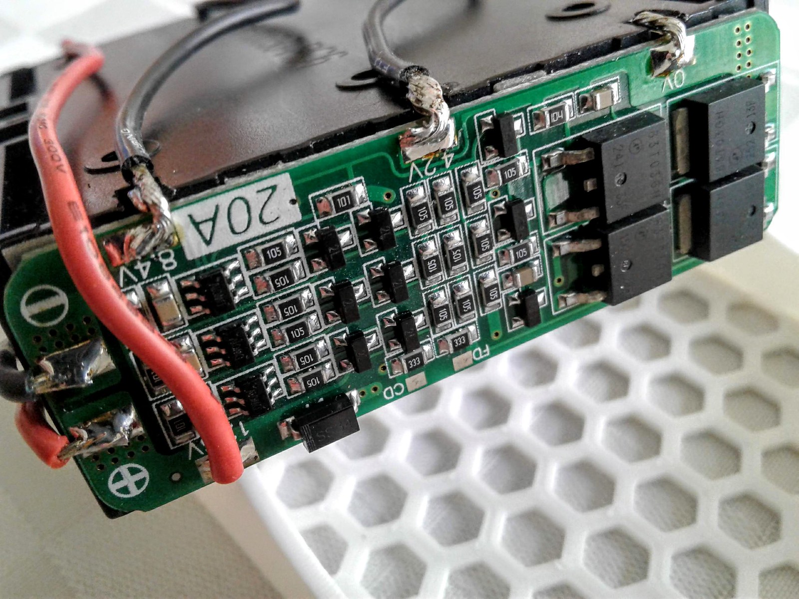
But the way I collect parts we
may have to revisit the regulator idea soon. I need to have some coin left for product when my card comes in.:sherlock:

How's yours coming along? Did you drop the 3x 14500's for 2x 18650's? I love that tube setup
 
PKOK,
Top Bottom