
You are using an out of date browser. It may not display this or other websites correctly.
You should upgrade or use an alternative browser.
You should upgrade or use an alternative browser.
VapCap DIY Induction Heating : Bits 'n' pieces
- Thread starter stardustsailor
- Start date
Diggy Smalls
Notorious
That's wicked man. I don't understand what the screen is for, otherwise, it looks killer. You are so talented.
I don't understand what the screen is for
")
100% charge : Voltmeter indication = 12.6 = Must Use !
80% charge : Voltmeter indication = 12.3
( Do not charge over 12.3 V for long battery service life )
40% charge : Voltmeter indication = 11.1
( For long battery service life : Charge as soon as 3S Li-ion cell pack voltage drops to 11.1 V )
20% charge : Voltmeter indication = 10.5 = Must Charge !
=> click <=
" 123 "= good to go
" 111 " = needs charging
")
Last edited:
My next DIY IH device is going to be placed & used exclusively on my desk ,
nearby the pc monitor.
So ...
- No Li-ion / LiPO Batteries. Power will be provided by an external 12 VDC / 10 A PSU .
- Will not have an "ON-OFF " switch .
- Will have the " work coil overheat protection " .
- Will have a 10 A fast fuse at the power line .
- Will have a smaller case ( 100 x 100 x 45 mm ) ,
than my first DIY IH device ( 100 x 160 x 55 mm ) .
- Will have 2 Pole mic connectors for power connection ,instead of the classic DC plug.
10 Amps are pretty much for the "wobbly " connection ,
between the classic DC plug & DC socket .
Some pics ...


Cheers.

nearby the pc monitor.
So ...
- No Li-ion / LiPO Batteries. Power will be provided by an external 12 VDC / 10 A PSU .
- Will not have an "ON-OFF " switch .
- Will have the " work coil overheat protection " .
- Will have a 10 A fast fuse at the power line .
- Will have a smaller case ( 100 x 100 x 45 mm ) ,
than my first DIY IH device ( 100 x 160 x 55 mm ) .
- Will have 2 Pole mic connectors for power connection ,instead of the classic DC plug.
10 Amps are pretty much for the "wobbly " connection ,
between the classic DC plug & DC socket .
Some pics ...
Cheers.
Last edited:
Front side : Desktop ( on the left ) vs Portable Tabletop (on the right )

Rear side

Bottom side

Top side

Rear side
Bottom side
Top side
Last edited:
Top view of the guts .

The MOSFET control switch (wrapped inside a heat shrink tube and covered with alum .tape ).

The heating tube /chamber .

The 10mm LED on the left and the wire fuse box on the right

Device's schematic :

The MOSFET control switch (wrapped inside a heat shrink tube and covered with alum .tape ).
The heating tube /chamber .
The 10mm LED on the left and the wire fuse box on the right
Device's schematic :
Abysmal Vapor
Supersniffer 2000 - robot fart detection device
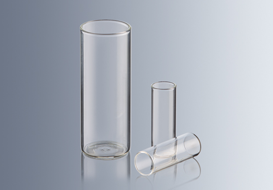
Looks really neat. Is the tube that vapcap sits in with open bottom ? Why not use a Vial or test tube botton and have all glass airpath in the IH chamber .Maybe one can inhale during operation that way . This are flat bottom testubes ,maybe good for the purpose ?
Just out of curiousity ,have you ever tried using the vapcap in the IH without the cap,during operation ? This concept could make a really interisting induction,open airflow vape).
Lol now i got an ultra thin logvape-core in a glass vial powered by induction idea...,totally separated airpath from electronics.
. This are flat bottom testubes ,maybe good for the purpose ?
Just out of curiousity ,have you ever tried using the vapcap in the IH without the cap,during operation ? This concept could make a really interisting induction,open airflow vape
).Lol now i got an ultra thin logvape-core in a glass vial powered by induction idea...,totally separated airpath from electronics.
Last edited:
Looks really neat. Is the tube that vapcap sits in with open bottom ? Why not use a Vial or test tube botton and have all glass airpath in the IH chamber .Maybe one can inhale during operation that way
Just out of curiousity ,have you ever tried using the vapcap in the IH without the cap,during operation ? This concept could make a really interisting induction,open airflow vape
Lol now i got an ultra thin logvape-core in a glass vial powered by induction idea...,totally separated airpath from electronics.
Indeed ,nice ideas you share !
No I 've not actually tried any of those .
Myself ,also I believe that induction heating has a lot of potentional ...
Last edited:

virtualpurple
Well-Known Member
That looks really dope! Very sleek and classy to me.
Charging 3S Li-ion battery pack with an ordinary 13-22 VDC PSU .
This is needed :
https://www.ebay.com/itm/263723928090
It has through -hole pads to accept a bi-color LED ,
indicating it's operation ( CC when charging & CV when battery pack is charged )
At it's input it can accept any voltage from 13 to 22 VDC and up to 2 Amps .
It outputs 12.6 VDC +/- 1% ( 12.47 - 12,73 VDC ) .
Balancing the charge of a 3S Li -ion battery pack .
https://www.ebay.com/itm/3S-11-1V-1...503004?hash=item3d3513eb9c:g:~NAAAOSwuxFYvXrq
And a better Step down charging module :
https://www.ebay.com/itm/Switch-Typ...831?_trksid=p2349526.m4383.l4275.c10#viTabs_0
https://www.ebay.com/itm/Switch-Typ...853?_trksid=p2349526.m4383.l4275.c10#viTabs_0
https://www.ebay.com/itm/Switch-Typ...831?_trksid=p2349526.m4383.l4275.c10#viTabs_0
https://www.ebay.com/itm/Switch-Typ...853?_trksid=p2349526.m4383.l4275.c10#viTabs_0

Well kept "secrets " ,in common view ...
cactusbastard
New Member
I must admit that you're basically my hero right now. I love what you're doing, I love how you're doing it, and I love that you're explaining it simply and thoroughly enough that I'm actually able to follow along!Induction Coil Thermal Protection .
How to attach the thermostat to the IH coil.
1 ) Wrap the coil with a round of baking paper ( 51 x 25 mm strip ) .
2 ) Now ,fully cover the baking paper ,by wraping with Kapton tape .One layer .
3 ) Place the thermostat at the middle of the coil's length.
4 ) Wrap around the thermostat with couple wrapping of Kapton .
Heat shrink tubing can also be used at this step,instead of wrapping with Kapton .
5 ) Connect one terminal of the thermostat to the Mosfet switch input " V+ " ,
while the other terminalo will be connected with the push button / tactle switch .
Anyhoo, what's the baking paper for? Is it just a belt and suspenders approach to coil insulation or is it for thermal insulation or vibration damping or something?
I must admit that you're basically my hero right now. I love what you're doing, I love how you're doing it, and I love that you're explaining it simply and thoroughly enough that I'm actually able to follow along!
Anyhoo, what's the baking paper for? Is it just a belt and suspenders approach to coil insulation or is it for thermal insulation or vibration damping or something?
Both !
But you can use Kapton tape ,instead .
Ok ...
Finished at last !
The "J.G. Verne " induction heater .
A unique piece !
Hand-decorated with stainless steel nuts and washers and hard disk salvaged aluminium parts ,
glow-in-the-dark resin and mica pigments .
Input : 5-12 VDC ,10 A
Fuse : 10A Fast
Coil protection : 80°C


Finished at last !
The "J.G. Verne " induction heater .
A unique piece !
Hand-decorated with stainless steel nuts and washers and hard disk salvaged aluminium parts ,
glow-in-the-dark resin and mica pigments .
Input : 5-12 VDC ,10 A
Fuse : 10A Fast
Coil protection : 80°C
Last edited:
The plans for another IH device and a battery power source unit .

IRF540N MOSFET Switch for the ZVS IH module activation

The Gate resistor ( Rgate ) should be placed / connected after the 10K
pull-down resistor ( R2 ) .If otherwise a "voltage divider "circuit is formed and at the gate
there is applied a bit lower voltage than the supplied .Better be safe ( than sorry ) when working with MOSFETs .The push-button / tactle switch debouncing filter circuitry -inside the grey rectangle-can be omitted .
https://www.infineon.com/dgdl/irf540n.pdf?fileId=5546d462533600a4015355e396cb199f
https://www.theengineeringprojects.com/2017/06/introduction-to-irf540.html
https://www.electronics-tutorials.ws/transistor/tran_7.html
http://www.bristolwatch.com/ele/tr2.htm
--------------------------------------------------------------------------------------------------
Gate Resistor
Using a low value resistor between the MOSFET driver and the MOSFET gate terminal dampens down any ringing oscillations caused by the lead inductance and gate capacitance which can otherwise exceed the maximum voltage allowed on the gate terminal. It also slows down the rate at which the MOSFET turns on and off. This can be useful if the intrinsic diodes in the MOSFET do not turn on fast enough.
If you are driving a MOSFET from a bouncy, possibly noisy, line (for instance relay contacts*), you should use a small series gate resistor close to the MOSFET, to suppress VHF oscillation. 22 ohms is plenty, you can use less.
If speed / propagation delay is critical you may need to try and avoid using a gate resistor or keep its value low. For instance with a 5V signal and a FDN335N, a 1K gate resistor can add around 200-400nS propagation delay (delayed switching from gate to drain).
For high current MOSFETs the Gate Channel Capacitance can be very high and a rapidly changing drain voltage can produce milliamps of transient Gate current. This could be enough to overdrive and even damage delicate CMOS driver chips. Having a series resistor is a compromise between speed and protection, with values of 100R to 10K being typical. Even without inductive loads there is dynamic gate current. Also, MOSFETs are extremely susceptible to damage caused by electrostatic discharge and can be damaged irreversibly by a single instance of Gate breakdown. For this reason it is a very good idea to use gate series resistors of 1K to 10K. This is especially important if the Gate signal comes from another circuit board.
If a MOSFET could be left floating then use a pull down resistor (100K to 1M is generally ok) from Gate to Source.
http://www.electronic-products-desi...ics/mosfets/using-mosfets-as-general-switches
*Or push buttons or tactile switches ...
Last edited:
virtualpurple
Well-Known Member
I love this thread and the sick little IH box you built!
Modifying the Working Coil
In order to fit the ZVS IH module with it's working coil inside a DIY case ,
quite often the working coil has to be slightly modified.
"Squeezed" a bit ( and reduce a bit of it's diameter to snuggly fit the Cloupor M3 glass tube ) .
This is done simply by gently twisting ( tightening ) the coil around the glass tube .
The glass tube should be covered with a tape of some sort ,before twisting the coil around it.

But how this mod affects the heating ?


http://www.sa-japan.com/sa-japan/catalog/CEIA_InductionHeatingPrinciples_FC040K0068v1uk.pdf
https://elearning.unipd.it/dii/plug...ce/content/1/1_induction_fundamentals_LEP.pdf
So the stronger the magnetic field ( B ) induced ,the higher
the eddy currents ,formed at the VapCap tip & cap .
B = μ0 * Ν *I / l
B = Magnetic Field
μ0 = vacuum permeability = 4π×10−7 H/m
N = Number of coil loops
I = Coil current ( up to 10 A for the 12V ZVS IH module )
l = length of coil
Since μ0 and I are constant values ,the magnetic field can be expressed as the ratio
of the number of coil turns (loops) to the coil length.
The more turns and/or shorter coil length ,the stronger the magnetic field formed .
B= N / l
So for the unmodified stock coil B = 10 / 0.028 = ~ 357
For the modified stock coil B = 11 / 0.025 = 440
ΔB = 83
The modified stock coil has ~23% stronger magnetic field over the unmodified stock coil .
How this mod affects the operating frequency ?
The working coil along with the two caps ,form an LC resonant circuit.
The unmodified stock coil has these dimensions
OD = 23 mm
ID = 19 mm
Coil diameter = ID + ( ( OD-ID ) /2 ) = 21 mm
Length = 28 mm
Turns = 10
Using an online " air core inductance "calculator ,like this one :
https://m0ukd.com/calculators/air-cored-inductor-calculator/
we calculate that it's inductance is 1162.369 nH
The two parallel caps are of 0.33 μF capacitance .
Thus their total capacitance is 0.66 μF or 660 nF or 660 ,000 pF
Having the values of capacitance and inductance of the LC circuit ,
we can calculate the resonant frequency with an online
" LC resonant Frequency " calculator :
https://www.daycounter.com/Calculators/LC-Resonance-Calculator.phtml
Where is calculated that the 5-12V ZVS IH module has a working frequency of 0.182 MHz or 182 kHz .

http://fuckcombustion.com/threads/v...op-and-in-car-use.23211/page-101#post-1307941
The new modified stock coil has these dimensions :
OD = 20 mm
ID = 16 mm
Coil diameter = ID + ( ( OD-ID ) /2 ) = 18 mm
Length = 25 mm
Turns = 11
Placing the above values on the air core inductance calculator :
https://m0ukd.com/calculators/air-cored-inductor-calculator/
The inductance of the modified stock coil is 1169.425 nH
Back to the " LC resonant Frequency " calculator :
https://www.daycounter.com/Calculators/LC-Resonance-Calculator.phtml
The 5-12V ZVS IH module now has a new working frequency of 0.181 MHz or 181 kHz
A small difference of 1000 Hz .
The operating frequency with the modified coil is 0.55% lower ,
than the operating frequency with an unmodified stock coil.
In order to fit the ZVS IH module with it's working coil inside a DIY case ,
quite often the working coil has to be slightly modified.
"Squeezed" a bit ( and reduce a bit of it's diameter to snuggly fit the Cloupor M3 glass tube ) .
This is done simply by gently twisting ( tightening ) the coil around the glass tube .
The glass tube should be covered with a tape of some sort ,before twisting the coil around it.
But how this mod affects the heating ?
http://www.sa-japan.com/sa-japan/catalog/CEIA_InductionHeatingPrinciples_FC040K0068v1uk.pdf
https://elearning.unipd.it/dii/plug...ce/content/1/1_induction_fundamentals_LEP.pdf
So the stronger the magnetic field ( B ) induced ,the higher
the eddy currents ,formed at the VapCap tip & cap .
B = μ0 * Ν *I / l
B = Magnetic Field
μ0 = vacuum permeability = 4π×10−7 H/m
N = Number of coil loops
I = Coil current ( up to 10 A for the 12V ZVS IH module )
l = length of coil
Since μ0 and I are constant values ,the magnetic field can be expressed as the ratio
of the number of coil turns (loops) to the coil length.
The more turns and/or shorter coil length ,the stronger the magnetic field formed .
B= N / l
So for the unmodified stock coil B = 10 / 0.028 = ~ 357
For the modified stock coil B = 11 / 0.025 = 440
ΔB = 83
The modified stock coil has ~23% stronger magnetic field over the unmodified stock coil .
How this mod affects the operating frequency ?
The working coil along with the two caps ,form an LC resonant circuit.
The unmodified stock coil has these dimensions
OD = 23 mm
ID = 19 mm
Coil diameter = ID + ( ( OD-ID ) /2 ) = 21 mm
Length = 28 mm
Turns = 10
Using an online " air core inductance "calculator ,like this one :
https://m0ukd.com/calculators/air-cored-inductor-calculator/
we calculate that it's inductance is 1162.369 nH
The two parallel caps are of 0.33 μF capacitance .
Thus their total capacitance is 0.66 μF or 660 nF or 660 ,000 pF
Having the values of capacitance and inductance of the LC circuit ,
we can calculate the resonant frequency with an online
" LC resonant Frequency " calculator :
https://www.daycounter.com/Calculators/LC-Resonance-Calculator.phtml
Where is calculated that the 5-12V ZVS IH module has a working frequency of 0.182 MHz or 182 kHz .
http://fuckcombustion.com/threads/v...op-and-in-car-use.23211/page-101#post-1307941
The new modified stock coil has these dimensions :
OD = 20 mm
ID = 16 mm
Coil diameter = ID + ( ( OD-ID ) /2 ) = 18 mm
Length = 25 mm
Turns = 11
Placing the above values on the air core inductance calculator :
https://m0ukd.com/calculators/air-cored-inductor-calculator/
The inductance of the modified stock coil is 1169.425 nH
Back to the " LC resonant Frequency " calculator :
https://www.daycounter.com/Calculators/LC-Resonance-Calculator.phtml
The 5-12V ZVS IH module now has a new working frequency of 0.181 MHz or 181 kHz
A small difference of 1000 Hz .
The operating frequency with the modified coil is 0.55% lower ,
than the operating frequency with an unmodified stock coil.
Last edited:
Switch Debounce
A much better way to eliminate push button / tactile switch VHF noise
and prolong the service life of the induction heating device .

*****
Parts used :
1x 100 Ohm / 250mW , resistor
1x 100nF / 100V ceramic or MKT/MKP ,capacitor
1x 5 Volt / 1 Watt ( 1N4733A ) ,Zener diode
1x MAX 6816 EUS+T , I.C.
https://gr.mouser.com/ProductDetail/Maxim-Integrated/MAX6816EUS+T?qs=1THa7WoU59EAx6vXEummCg==
https://www.digikey.com/product-detail/en/maxim-integrated/MAX6816EUS-T/MAX6816EUS-TCT-ND/774155
Circuit schematic :

Datasheets / AN :
https://datasheets.maximintegrated.com/en/ds/1896.pdf
https://www.jameco.com/jameco/products/prodds/36097vis.pdf
https://www.maximintegrated.com/en/app-notes/index.mvp/id/287
Tactile switch /Push Button debouncing module pcb :

Single layer FR4 - Top side ( only SMD components used )
R1 : 100 Ω
DZ1 : SMD Zener diode 5V / 1W
C1 : SMD Ceramic capacitor 100 nF
C2 (optional ) : SMD Ceramic capacitor 100 nF
U1 : MAX6816EUS-T
Using pins at "GND" & "OUT " pads ,
the pcb can be soldered directly to the 15A " 400W MOSFET Switch module "
A much better way to eliminate push button / tactile switch VHF noise
and prolong the service life of the induction heating device .
*****
Parts used :
1x 100 Ohm / 250mW , resistor
1x 100nF / 100V ceramic or MKT/MKP ,capacitor
1x 5 Volt / 1 Watt ( 1N4733A ) ,Zener diode
1x MAX 6816 EUS+T , I.C.
https://gr.mouser.com/ProductDetail/Maxim-Integrated/MAX6816EUS+T?qs=1THa7WoU59EAx6vXEummCg==
https://www.digikey.com/product-detail/en/maxim-integrated/MAX6816EUS-T/MAX6816EUS-TCT-ND/774155
Circuit schematic :
Datasheets / AN :
https://datasheets.maximintegrated.com/en/ds/1896.pdf
https://www.jameco.com/jameco/products/prodds/36097vis.pdf
https://www.maximintegrated.com/en/app-notes/index.mvp/id/287
Tactile switch /Push Button debouncing module pcb :
Single layer FR4 - Top side ( only SMD components used )
R1 : 100 Ω
DZ1 : SMD Zener diode 5V / 1W
C1 : SMD Ceramic capacitor 100 nF
C2 (optional ) : SMD Ceramic capacitor 100 nF
U1 : MAX6816EUS-T
Using pins at "GND" & "OUT " pads ,
the pcb can be soldered directly to the 15A " 400W MOSFET Switch module "
Last edited:
Hackerman
User
@stardustsailor , hopefully, I am not too off topic but since the thread is technical in nature, I will ask.....
On the SJK 'dental' induction heaters the wire used to make the coil is very small and is wrapped many many times around the coil (dozens, it looks like).
What is the difference between this type of coil and the coil that is real thick and wrapped 10 (or 11) times.
Thanks again from all of us for the wonderful information.
@stardustsailor
On the SJK 'dental' induction heaters the wire used to make the coil is very small and is wrapped many many times around the coil (hundreds, it looks like).
What is the difference between this type of coil and the coil that is real thick and wrapped 10 (or 11) times.
Many wraps : Strong magnetic field .
http://www.sa-japan.com/sa-japan/catalog/CEIA_InductionHeatingPrinciples_FC040K0068v1uk.pdf
Small wire diameter (thus high resistance ) : Low operating current .
Made to induce a strong magnetic field with low current (thus with a high voltage ) .
Also keeps the cost down ( less Copper used ,no need for extra power supply -uses the mains voltage ).
Quite prone to fail (overheat ),
if/when used with a larger (mass-wise ) than optimum object-to-be-heated.
Last edited: