VapCap Induction Heater for Desktop and in Car Use

SloJimFizz

Unknown Member
Holy crap @phattpiggie :bowdown:

Does anyone know if the jarhead can be used in the car with a cigarette lighter adapter.
You can just get the adaptor to turn your cigarette lighter into a 110v plug.
My cigarette lighter adaptor has a 110v outlet and 2 usb ports. Way more useful to me than the unused lighter.

Dude, this is great. I really like the look of it.

$5.00 at Hobby Lobby. :tup:
 

Edgedamage

Well-Known Member
Battery level indcator, what do those pretty lights really mean? I made a quick test setup using a 23vdc wall wart, and a ajustable step down voltage regulator. I got two from the same vendor on ebay and they match on readings. I have three more from a diffrent vender and will re test.
Red led not really cool with this one. It's range is 2.2vdc dim, to 4.4vdc bright until the first blue led lights. I would like to see it cutoff at 9.5vdc. Each cell would read 3.17vdc

First blue led lights at 10.29vdc. Each cell should read 3.43vdc

Second led lights at 10.88vdc. Each cell should read 3.63vdc

Third led lights at 11.50vdc. Each cell should read 3.83vdc

Fourth led lights at 12.1vdc. Each cell should read 4.03vdc

This testing was done to see what I am doing to my 18650's. 18650's are the battery chemistry I am used to. I have no understanding of LIPOs, and their safe upper and lower voltage ranges.
 
Last edited:

FryMeALiver

New Member
Would anyone have any notion as to the differences between induction heating units........as in the ZVS low voltage heating units + the coil that everyone seems to use. I bought one a while ago from Amazon
( https://www.amazon.co.uk/gp/product/B0749QKJ8M/ref=oh_aui_detailpage_o06_s02?ie=UTF8&psc=1 )

It is installed and has been working well without any bothers for about 3 months. Since then I bought two more heating units, to build IH's for some friends, neither of which seem to be working. I have redone my connections, swapped wires as well as mosfet switches etc. The two heaters I bought are these two
( https://www.ebay.co.uk/itm/Pro-5V-12V-Low-Voltage-ZVS-Induction-Heating-Power-Supply-Module-Heater-Coil-PP/282998605381?ssPageName=STRK:MEBIDX:IT&_trksid=p2060353.m2749.l2649)
and
( https://www.amazon.co.uk/gp/product/B01J7Q85DQ/ref=oh_aui_detailpage_o03_s00?ie=UTF8&psc=1 )

These three heaters seem to be identical, except for the numbers that appear on the attached pcb. The original says 'mini-V1.1RE', as does one of the others I bought, while the third says 'mini-028'.

Ok so, having said all that...... I have checked the voltages coming from the circuits that I wired into to install these. I am getting about 12.4v from all of them, with a solid red light on the mosfet until I install the heating units, then it drops to nothing. It appears to be a problem similar to when I plugged my original heater into a 12v 1.5a power supply. Obviously it didn't work. So I bought a 12v 6amp, and that is what I have been using. It seems the two newer heating units are behaving in a way similar to when I tried to run my original unit off a 1.5a brick, even though I have been plugging them into my 6amp brick.

So my question after all that............ is there a difference between these heating units, do they require something like 20 amps or something like that????? Can anyone then link me to a lock heating unit. One that is guaranteed to work with my 12v 6a power supply. I am prepared to rebuy, its just I want to make sure what I am buying will work........

Any help, any advice............. anything, is helpful. I don't know where else to turn to ask for assistance.
Thanks all
 
Last edited:
FryMeALiver,
  • Like
Reactions: Pipes

dmisc

Member
I'm no longer using the Xbox PA. I'm using a generic 12v 6amp one from Amazon.
I've tried several configurations and I always get the little blue led on the heater blinking in unison with the power adapter and no heat. I just tried plugging the power adapter directly into the heater without anything else in the circuit and i'm getting the same blinking led. No sign of damage underneath the coils on the heater. I may have damaged it somehow when I was trying to use the xbox adapter.


By any chance, were you able to figure out the issue? I have the same blinking blue led. And I am using a generic 12v 8a supply. I've even tried a 12v 1.5a supply and I still get that blinking blue led.
 
dmisc,

stardustsailor

Well-Known Member
Accessory Maker
As the ZVS induction heating module lacks any "blinking LED "circuitry ,
then it must be the PSU that actually makes the LED blink .
A blinking power LED at the ZVS IH module means that the PSU is constantly
brought into protection mode and then it recovers / self-resets ,
only to fall again into protection mode and so on .That is called a " hiccup mode " .
That 's why the blinking LED .

The hiccup mode usually happens :

1 ) when the output has no load ( CC PSU )

2 ) output overload ( CV & CC PSU )

3 ) output over voltage ( CV PSU )

4 ) output over current ( CC PSU )

https://www.jameco.com/Jameco/workshop/techtip/power-supply-hiccup-mode.html

https://www.power-supplies-australia.com.au/blog/mean-well-power-supply-hiccup-mode

https://www.microsemi.com/document-portal/doc_view/131948-an-8-hiccup-mode-current-limiting
 
Last edited:

Pipes

Addicted DIY Enthusiast
Accessory Maker
Would anyone have any notion as to the differences between induction heating units........as in the ZVS low voltage heating units + the coil that everyone seems to use. I bought one a while ago from Amazon
( https://www.amazon.co.uk/gp/product/B0749QKJ8M/ref=oh_aui_detailpage_o06_s02?ie=UTF8&psc=1 )

It is installed and has been working well without any bothers for about 3 months. Since then I bought two more heating units, to build IH's for some friends, neither of which seem to be working. I have redone my connections, swapped wires as well as mosfet switches etc. The two heaters I bought are these two
( https://www.ebay.co.uk/itm/Pro-5V-12V-Low-Voltage-ZVS-Induction-Heating-Power-Supply-Module-Heater-Coil-PP/282998605381?ssPageName=STRK:MEBIDX:IT&_trksid=p2060353.m2749.l2649)
and
( https://www.amazon.co.uk/gp/product/B01J7Q85DQ/ref=oh_aui_detailpage_o03_s00?ie=UTF8&psc=1 )

These three heaters seem to be identical, except for the numbers that appear on the attached pcb. The original says 'mini-V1.1RE', as does one of the others I bought, while the third says 'mini-028'.

Ok so, having said all that...... I have checked the voltages coming from the circuits that I wired into to install these. I am getting about 12.4v from all of them, with a solid red light on the mosfet until I install the heating units, then it drops to nothing. It appears to be a problem similar to when I plugged my original heater into a 12v 1.5a power supply. Obviously it didn't work. So I bought a 12v 6amp, and that is what I have been using. It seems the two newer heating units are behaving in a way similar to when I tried to run my original unit off a 1.5a brick, even though I have been plugging them into my 6amp brick.

So my question after all that............ is there a difference between these heating units, do they require something like 20 amps or something like that????? Can anyone then link me to a lock heating unit. One that is guaranteed to work with my 12v 6a power supply. I am prepared to rebuy, its just I want to make sure what I am buying will work........

Any help, any advice............. anything, is helpful. I don't know where else to turn to ask for assistance.
Thanks all
This has been an ongoing quality issue with these drivers. They use the cheapest FETs or maybe even rejects from huge batches. I had many issues with them for the first few months as they would blow or have random firing issues. Very few are actually up to snuff. You notice the price change from the one that works... Might be a clue for what grade of components they use.
I gave up and don't even check them and just replace them out right off the get-go. FET replacements are cheap enough, but require some soldering skills to change out. Since I started this procedure, failures became very rare. Night and day in fact. Highly recommend you get a few.
You need a sharp pointy soldering iron for the chore. Twist the big honking coils so you have access to the FETs and use the point of soldering iron to lift the legs off the board. Sometimes the legs will break off the FET but that's OK. Then heat the rear close to the top of the FET and apply a dap of solder to help pass the heat into the board. Wait a few seconds until you can use the iron to slide the FET off the board. Clean up and smooth over the solder pads with the iron. Lay the new FET in place and tack the legs down. Then apply heat and solder to the rear heat sink of FET until the solder gets sucked under the FET. Dab a tad more solder to the legs and ensure the work is sound.
Always replace BOTH drivers at the same time. Replacing the first time is fairly easy as the factory soldering is poor and legs lift easy. Replacing the second (or more) time is much harder as you need to use solder wick to clean the legs off before lifting them.
Good luck!

Now for a fun update. I have added a couple different head inserts for the Jarheads. Besides Trump, you can now request Dracula or a Zombie head instead. If you already own a JH and want to change the head, you can download and print the new heads here. And the better news is I currently have stock with the JHs as well as the BareBones. Wait time for the PSM is also reduced to 2 months. Have updated my FAQ document to reflect the changes.


:science:
 
Last edited:

FryMeALiver

New Member
Thank you Pipes, super clear reply and your explanation makes perfect sense to me. What you suggest sounds tricky but my soldering skills have definitely been improving so I am at least going to try and improve them some more..........I will let you know how I get on, coz why not!

I like the heads by the way, gonna refer my buddies to you if/when I am unsuccessful.

Thanks again for being a legend, and take care of yourself.......
 

dmisc

Member
As the ZVS induction heating module lacks any "blinking LED "circuitry ,
then it must be the PSU that actually makes the LED blink .
A blinking power LED at the ZVS IH module means that the PSU is constantly
brought into protection mode and then it recovers / self-resets ,
only to fall again into protection mode and so on .That is called a " hiccup mode " .
That 's why the blinking LED .

The hiccup mode usually happens :

1 ) when the output has no load ( CC PSU )

2 ) output overload ( CV & CC PSU )

3 ) output over voltage ( CV PSU )

4 ) output over current ( CC PSU )

https://www.jameco.com/Jameco/workshop/techtip/power-supply-hiccup-mode.html

https://www.power-supplies-australia.com.au/blog/mean-well-power-supply-hiccup-mode

https://www.microsemi.com/document-portal/doc_view/131948-an-8-hiccup-mode-current-limiting


Thank you for the information.

Would the ZVS be the reason why it went into hiccup mode? The reason why I ask is because I tried 2 separate power supplies. I just purchased another power supply. A 12v 6a one, and i dont want to connect it to the ZVS because im scared that it might pop the new supply into hiccup mode.

The funny thing is, when I first got all the parts, I connected them together. The blue led came on, but it took maybe 30 seconds to 1 minute for any heating action to happen. Once, the coil started heating, it was fine for a couple of hits with the vapcap. Once i unplug the power supply, it was like reset...I would plug it back in for another session, and would have to wait 30 seconds to a minute for it to start heating up.

Also, after reading from the links you posted, i am not really sure how to fix the hiccup mode on my 12v 8a supply. The link to Jameco gave a suggestion, but it seems way over my head. A dummy load? I have no idea where to start with that.

Any idea would be appreciated.
 

stardustsailor

Well-Known Member
Accessory Maker
A switching power supply will recover from hiccup mode by itself either automatically
or when the PSU is switched OFF and powered back ON .
You do not have to do anything special .

It is the connected device that "trips" the protection of the PSU .
(and the PSU's " self recovery mode " that makes the blue LED blink )
That means that the ZVS module has a short circuit somewhere .
At best case , one of the Magically Obliterated ,Smoke and Fire Emitting Transistors is fried .
 
stardustsailor,
  • Like
Reactions: Hogni

nachooo

Well-Known Member
The booster was for driving the gates only. Low power. The main drive voltage isn't as important for it to oscillate.
Not really feasible to boost the drive voltage as would be a much bigger undertaking.
Getting into ecig mod power stuff now which is not a pure DC but rather pulsating DC and wattage is determined by duty cycle. Good for driving a heating element but not good for supplying an oscillating type circuit.
If you really want play play, there are other ways to cut down the size. :science:
You can ditch those big ass coils and replace with these guys and eliminate one of the capacitors all together. You can mount both these coils where the capacitor is removed from. This will cause the unit to oscillate at a much lower frequency but still work very well. I have done this in my experiments with very good results. :science:
Now you have room for the 3S cell in your design...?
First I want to say you thank you again Pipes...
Well I bought the little coils, then I removed the old ones...I even did not desold them..only cut the metal..I did the same with the one of the black capacitors..I cut the metal wires… I found a nice Scorpion logo hidden there :). I sold the Little coils in the place that the old capacitor was before. I put the unit in my 10 Amps, 12 volt power unit… close my eyes hoping this thing did not explode ...and VOILA!!! it Works...and it woeks even better that my other unit.. I mean my dynavap did the click even one or two seconds earlier… Well I can do a really mini portable now… Thanks Pipes..thanks thanks
Is curious that i bought tmy two inductors at the same place with about 3 months difference and the first one when is on have a green led and the second one has a blue led...

https://imgur.com/a/A9GGLxC

pveLJzf.jpg
 
Last edited:

Dick Emery

New Member
Could a 250w box mod power one of those induction coils? I mean could I just hook one of those coils up to the +- posts on an RDA?

It's no doubt been asked before but what is the size of the glass tube? Can I buy it precut?
 
Last edited by a moderator:
Dick Emery,

nachooo

Well-Known Member
Hello again Pipes, as I told you before, I changed the big coils for the little ones and I removed one capacitor, the unit works nice… but..if I use the FET moudule with the momentary switch..the red light in the module appears as usual, also the blue light in the inductor, but the unit does not work...it only works without the fet module...
The same FET module works ok with other inductor with the big coils and the two capacitors…
Do you know the reason for this? Should I use other type of FET module? Can I use instead the Little switch a big momentary switch like those used for ignition of cars and avoid the fet module at all?
Thanks for reading
 
nachooo,

Pipes

Addicted DIY Enthusiast
Accessory Maker
There should be no difference using the FET switch. You have not changed anything but values and oscillating frequency. Maybe a wiring slip up?

@Dick Emery, a box mod will not work as a power source as not true DC but rather a PWM, "Pulse Width Modulator" type source for driving heater elements which don't care what the DC looks like. Uses the duty cycle to determine the power level.
An Induction driver circuit needs pure DC for the oscillator to achieve a stable oscillation.
The link for the glass tubes is in my FAQ. :science:
 

nachooo

Well-Known Member
There should be no difference using the FET switch. You have not changed anything but values and oscillating frequency. Maybe a wiring slip up?

@Dick Emery, a box mod will not work as a power source as not true DC but rather a PWM, "Pulse Width Modulator" type source for driving heater elements which don't care what the DC looks like. Uses the duty cycle to determine the power level.
An Induction driver circuit needs pure DC for the oscillator to achieve a stable oscillation.
The link for the glass tubes is in my FAQ. :science:
I checked and rechecked it a lot of times...and checked the FET again with other inductor..I just dont know what happen...
 
nachooo,

Pipes

Addicted DIY Enthusiast
Accessory Maker
You have me stumped as should work the same.
However, there is a plan "B".
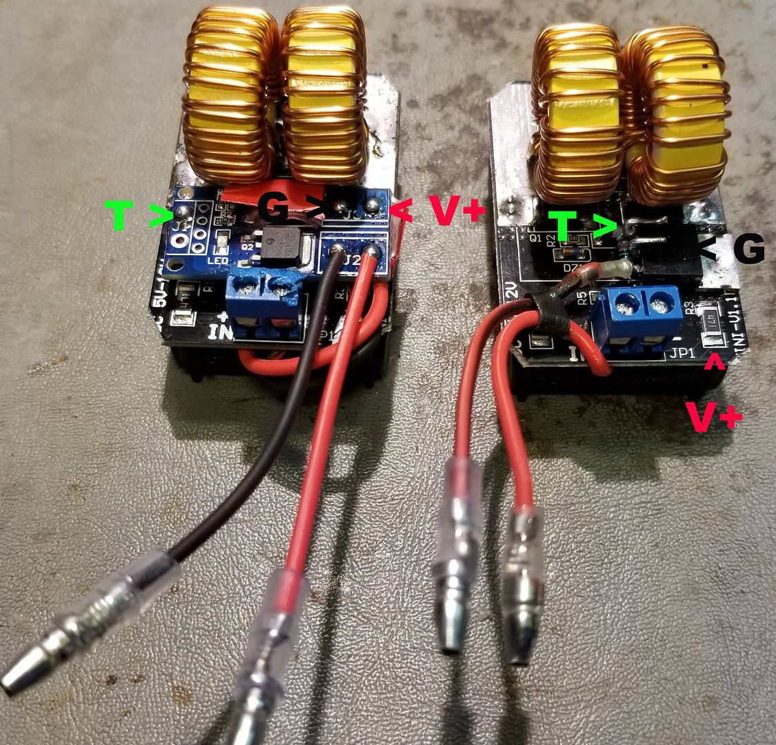
I stopped using those FET boards and have been using a single IRF540N FET and a 10 K resistor instead. Takes less room and more secure. The 10 K resistor goes between the gate and drain. Zoom in on the picture and you'll see it at the bottom of the FET. I cleared a spot on the board which is all ground and soldered the FET through the hole directly to the board. This is the new main ground for the circuit. The input ground is the source of the FET and the gate is the new "trigger" input. I've marked the connection points of the two circuits below. They have identical function. The Ground connection is for the power indicator LED inside the tube.


Enjoy and good luck! :science:
 

phattpiggie

Well-Known Member
Accessory Maker
I broke the glass tube a while ago and it was filthy inside.
This video shows why, it's shatter on cotton with the original sound.
You can see when I remove the VC there is vapor coming from the Mini. I've noticed it in the past and this clip shows it really well.
The glass was coated with resin so for anyone planning on flying with a well abused Mini it may be worth Iso'ing the tube beforehand.
Remember dogs can say hello 50 different ways with their backsides and they could well pick up on a dirty Mini.
Freshly charged battery.
 

stardustsailor

Well-Known Member
Accessory Maker
The 10 K resistor goes between the gate and drain.
Most probably you mean between the Gate and the Source pins .
This is done to bring the Gate to ground in order to switch off the MOSFET and avoid
any unwanted /accidental capacitative driving of the Gate .

Also it would be a good idea to place a Gate resistor ( 100R to 1K ).
Ringing (aka parasitic oscillation) can be induced by the gate capacitance in series with the trace's / wire's inductance and will lead the MOSFET to dissipate lot's of power,
'cause it will not turn on quickly enough ,thus the current at drain/source path ,combined with the rather high drain-source impedance will heat the device up. A low value resistor will dampen the parasitic oscillation .

http://irf.custhelp.com/app/answers/detail/a_id/215

:2c:
 
Last edited:

stardustsailor

Well-Known Member
Accessory Maker
That's typical push button contact "bouncing ".
Happens also with mechanical relays ,but it's more exaggerated there.

A simple RC debouncing filter will minimize bouncing noise .
C: 0.5 -1 μF x switching current (A)
R : 0.5 - 1 Ohm x switching voltage (V)

In our case if Rgate = 470R ,then I = 12 / 470 = 0.0255 A
Cfilter = 0.012 - 0.0255 uF ( 10- 22 nF )
Rfilter = 6 -12 Ohm

https://forum.arduino.cc/index.php?topic=62065.0

https://www.allaboutcircuits.com/technical-articles/switch-bounce-how-to-deal-with-it/

It can also be done (more effectively )with a single Schmitt trigger Inverter in parallel with a resistor
,but it needs extra circuitry (lowering the voltage from 12 V to 5 V ) .

http://members.ee.net/brey/Debounce.PDF

http://www.ti.com/lit/ds/symlink/sn74lvc1g14.pdf
 
Last edited:
Top Bottom